Table of Contents
Advertisement
SERVICE MANUAL
Ver 1.0 2003.07
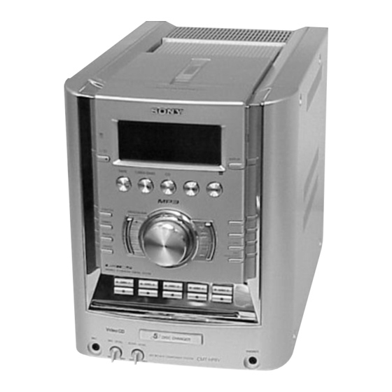
HCD-HP8V is the Amplifier, CD player, Tape
Deck and Tuner section in CMT-HP8V.
Main unit
Amplifier section
The following measured at AC 120, 127, 220, 240 V
50/60 Hz
DIN power output (rated): 60 + 60 watts (6 ohms at 1
kHz, DIN)
Continuous RMS power output (reference):
60 + 60 watts (6 ohms at 1
kHz, 10% THD)
Inputs
MD IN (phono jacks):
Sensitivity 250 mV,
impedance 47 kilohms
MIC (phone jack):
Sensitivity 1 mV,
impedance 10 kilohms
Outputs
PHONES (stereo minijack):
Accepts headphones of 8
ohms or more
MD OUT (phono jack):
Impedance 1 kilohm
VIDEO OUT (phono jack):
Max. output level 1Vp-p,
unbalanced, Sync
negative, load impedance
75 ohms
SPEAKER:
Accepts impedance of 6 to
16 ohms.
Sony Corporation
9-877-476-01
2003G1678-1
Home Audio Company
© 2003.07
Published by Sony Engineering Corporation
HCD-HP8V
Model Name Using Similar Mechanism
CD Mechanism Type
CD
Section
Base Unit Name
Optical Pick-up Name
Model Name Using Similar Mechanism
TAPE
Section
Tape Transport Mechanism Type
SPECIFICATIONS
CD player section
System
Compact disc and digital
audio system
Laser
Semiconductor laser
(λ=780 nm)
Emission duration:
continuous
Frequency response
2 Hz – 20 kHz (±0.5 dB)
Wavelength
780 – 790 nm
Signal-to-noise ratio
More than 90 dB
Dynamic range
More than 90 dB
Video color system format
NTSC, PAL
Tape deck section
Recording system
4-track 2-channel, stereo
Frequency response
50 – 13,000 Hz (±3 dB),
using Sony TYPE I
cassettes
MICRO HI-FI COMPONENT SYSTEM
E Model
NEW
CDM69BH-30BD62
BU-30BD62
A-MAX.3
HCD-EP515
CMAL1Z234A
Tuner section
FM stereo, FM/AM superheterodyne tuner
FM tuner section
Tuning range
87.5 – 108.0 MHz
Antenna
FM lead antenna
Antenna terminals
75 ohms unbalanced
Intermediate frequency
10.7 MHz
AM tuner section
Tuning range
Middle Eastern model:
531 – 1,602 kHz
(with the tuning interval
set at 9 kHz)
Other models:
530 – 1,710 kHz
(with the tuning interval
set at 10 kHz)
531 – 1,602 kHz
(with the tuning interval
set at 9 kHz)
Antenna
AM loop antenna
Antenna terminals
External antenna terminal
Intermediate frequency
450 kHz
Advertisement
Table of Contents

Related Manuals for Sony HCD-HP8V


Summary of Contents for Sony HCD-HP8V
- Page 1 HCD-HP8V SERVICE MANUAL E Model Ver 1.0 2003.07 HCD-HP8V is the Amplifier, CD player, Tape Deck and Tuner section in CMT-HP8V. Model Name Using Similar Mechanism CD Mechanism Type CDM69BH-30BD62 Section Base Unit Name BU-30BD62 Optical Pick-up Name A-MAX.3 Model Name Using Similar Mechanism...
- Page 2 COMPONENTS IDENTIFIED BY MARK 0 OR DOTTED LINE WITH MARK 0 ON THE SCHEMATIC DIAGRAMS AND IN THE PARTS LIST ARE CRITICAL TO SAFE OPERATION. REPLACE THESE COMPONENTS WITH SONY PARTS WHOSE PART NUMBERS APPEAR AS SHOWN IN THIS MANUAL OR IN SUPPLEMENTS PUBLISHED BY SONY.
-
Page 3: Table Of Contents
HCD-HP8V TABLE OF CONTENTS 1. SERVICING NOTES 6. MECHANICAL ADJUSTMENTS ······················································· 4 ····························· 24 7. ELECTRICAL ADJUSTMENTS ······························· 25 2. GENERAL ·········································································· 6 8. DIAGRAMS ······································································ 28 3. DISASSEMBLY 8-1. Block Diagram — CD SERVO Section — ················· 30 3-1. Case (Side-L)(Side-R), —... -
Page 4: Servicing Notes
HCD-HP8V SECTION 1 SERVICING NOTES Notes on chip component replacement NOTES ON LASER DIODE EMISSION CHECK • Never reuse a disconnected chip component. The laser beam on this model is concentrated so as to be focused on • Notice that the minus side of a tantalum capacitor may be dam- the disc reflective surface by the objective lens in the optical pick- aged by heat. - Page 5 HCD-HP8V Service Position of the Tape Cassette Mechanism Deck Service Position of the CD Mechanism Deck...
-
Page 6: General
HCD-HP8V SECTION 2 GENERAL This section is extracted from instruction manual. List of button locations and reference pages How to use this page Illustration number Use this page to find the location of buttons and other TAPE A/B 5 ( 18, 19 parts of the system that are mentioned in the text. -
Page 7: Setting The Clock
HCD-HP8V Remote control ALPHABETICAL ORDER BUTTON DESCRIPTIONS ?/1 (power) 4 (7, 8, 16, 22, 23, A – N O – Z ALBUM +/– wh (10, 13) ON SCREEN qs (26) m/M (rewind/fast forward) CD es (9, 11, 13, 16, 18, 19) PLAY MODE e;... -
Page 8: Disassembly
HCD-HP8V SECTION 3 DISASSEMBLY • This set can be disassembled in the order shown below. CASE (SIDE-L) (SIDE-R), TAPE MECHANISM DECK (CMAL1Z234A)) BACK PANEL SECTION FRONT PANEL SECTION PANEL BOARD MAIN BOARD PWR AMP BOARD, POWER TRANSFORMER CD MECHANISM DECK... -
Page 9: Case (Side-L)(Side-R), Tape Mechanism Deck (Cmal1Z234A)
HCD-HP8V Note: Follow the disassembly procedure in the numerical order given. 3-1. Case (Side-L)(Side-R), Tape Mechanism Deck (CMAL1Z234A) 7 two screws 8 top panel section (BVTP3 × 16 ) 5 two screws 4 four screws (BVTP3 × 16 ) qd tape mechanism deck... -
Page 10: Panel Board
HCD-HP8V 3-3. Panel Board 4 PANEL board 3 six claws 2 ten screws (BVTP2.6 × 8) 1 knob (VOL) 3-4. Back Panel Section 6 connector 8 back panel section (CN908) 4 connector 2 three screws (CN503) (BVTP3 × 10 ) 3 two screws (BVTP3 ×... -
Page 11: Main Board
HCD-HP8V 3-5. MAIN Board 5 w ire (flat type) 9p (CN303) 4 w ire (flat type) 37p (CN402) 3 connector (CN404) 1 connector (CN907) 9 MAIN board 2 two screws (BVTP3 × 8) 8 connector 7 w ire (flat type) -
Page 12: Cd Mechanism Deck (Cdm69Bh-30Bd62)
HCD-HP8V 3-7. CD Mechanism Deck (CDM69BH-30BD62) 1 two screws (BVTP3 × 8 ) 3 blacket (TR) 2 two screws (BVTP3 × 8 ) 5 four screws (BVTP3 × 8 ) 7 CD mechanism deck (CDM69BH-30BD62) 6 w ire (flat type) -
Page 13: Base Unit Section
HCD-HP8V 3-9. Base Unit Section 2 screw (DIA. 12) 3 boss 1 floating screw (+PTPWHM2.6) 4 boss 7 base unit section 6 boss 5 boss 3-10. Base Unit (BU-30BD62) 4 floating screw (+PTPWHM2.6 × 6) q; base unit (BU-30BD62) 8 insulator (BU30) 1 floating screw (+PTPWHM2.6 ×... -
Page 14: Bd Board
HCD-HP8V 3-11. BD Board 2 wire (flat type) (16 core) 1 Remove the solder (four portions). 3 BD board... -
Page 15: Sw Board, Bracket (Top) Assy
HCD-HP8V 3-12. SW Board, Bracket (Top) Assy 4 SW (3) board 5 SW (4) board 3 SW (2) board 1 four screws (BTP2.6 × 6) 6 six screws (BVTP2.6 × 8) 2 SW (1) board 7 bracket (top) assy 3-13. -
Page 16: Motor (Stocker) Assy (Stocker)(M761)
HCD-HP8V 3-14. Motor (Stocker) Assy (Stocker)(M761) 3 two screws (BVTP2.6 × 8) 2 Remove two solders 5 STOCKER MOTOR board 6 motor (stocker) assy (stocker) (M761) 1 belt (mode) 3-15. Motor (Roller) Assy (Roller)(M781) 3 two screws 2 Remove two solders. -
Page 17: Motor (Mode) Assy (Mode)(M771)
HCD-HP8V 3-16. Motor (Mode) Assy (Mode)(M771) 3 two screws (BVTP2.6 × 8) 1 Remove five solders 4 MODE MOTOR board of rotary encoder. 6 motor (mode) assy (mode) (M771) MODE MOTOR board 2 Remove two solders of motor (M771) 5 belt (mode V) 3-17. -
Page 18: Timing Belt (Front/Rear)
HCD-HP8V 3-18. Timing Belt (Front/Rear) 3 slider (mode cam) assy 7 two gears (center) When install three timing belts, its pass under each claws. 8 timing belt (rear) timing belt (rear) 5 two gears 9 timing belt (rear) (center) claw... -
Page 19: Sensor Board
HCD-HP8V 3-20. SENSOR Board ql harness qk claw q; cam (eject lock) : Note 9 screw (PTPWH2.6 × 8) qh two claws qd gear (eject lock) qj rotary encoder 8 shaft qs cam (BU U/D) (S771) wa SENSOR board (shutter) w;... -
Page 20: Assembly
HCD-HP8V SECTION 4 ASSEMBLY • This set can be assembled in the order shown below. 4-1. How to Install the Cam (Eject Lock) 1 Rotate the cam (BU U/D) fully in the direction of arrow. 2 Engage the gear (eject lock) and the gear of the cam (eject lock) aligning the mark with the center of the gear (eject lock). -
Page 21: How To Install The Gear (Mode C)
HCD-HP8V 4-3. How to Install the Gear (Mode C) 1 Align the mark on the rotary encoder (S771) with the projection of the assy. 2 Check that the cam (BU U/D) can not be rotated in the direction of arrow. -
Page 22: How To Install The Rotary Encoder (S702), Gear (Stocker Communication)
HCD-HP8V 4-5. How to Install the Rotary Encoder (S702), Gear (Stocker Communication) 4 gear 5 screw (stocker communication) (PTPWH2.6 × 8) 3 screw 7 two screws (PWH2 × 6) (PTPWH2.6 × 8) 1 rotary encoder Engage the rotary encoder (S702) -
Page 23: Test Mode
HCD-HP8V SECTION 5 TEST MODE [AM Channel Step 9 kHz/10kHz Selection Mode] [Panel Test Mode] * Either the 9 kHz step or 10 kHz step can be selected for the AM * All fluorescent segments, LEDs, keys, volume and headphone channel step. -
Page 24: Mechanical Adjustments
HCD-HP8V SECTION 6 MECHANICAL ADJUSTMENTS • TAPE MECHANISM DECK SECTION [AMP Test Mode] Precaution Procedure: 1. Clean the following parts with a denatured alcohol-moistened Press the ?/1 button to turn the set on. swab: To enter the test mode, press the three buttons x ,... -
Page 25: Electrical Adjustments
HCD-HP8V SECTION 7 ELECTRICAL ADJUSTMENTS Mode: Playback DECK SECTION 0 dB=0.775 V Note: Confirm each contents of this section first of all. If the results are PWR AMP board not satisfied, do the adjustment. SPEAKER terminals (JK501) test tape Demagnetize the record/playback head with a head... - Page 26 HCD-HP8V CD SECTION Note: Clear RF signal waveform means that the shape “ ◊ ” can be clearly distinguished at the center of the waveform. Note: RF signal waveform 1. CD Block is basically designed to operate without adjustment. Therefore, check each item in order given.
- Page 27 HCD-HP8V VIDEO SECTION – VMP BOARD (Component Side) – Video Level Check (Audio Level/Video Clock/Audio Servo Clock Check) TP308 oscilloscope (V-OUT) VMP board TP308 (V-OUT) – TP70 (54 MHz) level meter VMP board TP415 (L-OUT) TP413 (R-OUT) – TP182 (4.2336 MHz)
-
Page 28: Diagrams
HCD-HP8V SECTION 8 DIAGRAMS • Circuit Boards Location SUB TRANS board SENSOR (FAN) board PWR TRANS board PWR AMP board MAIN board PANEL board STOCKER MOTOR board JACK board ST ENCODER board ROLLER MOTOR board SW (4) board VMP board... - Page 29 HCD-HP8V • Waveforms THIS NOTE IS COMMON FOR PRINTED WIRING For printed wiring boards. – BD Board – – PANEL Board – – VMP Board – Note: BOARDS AND SCHEMATIC DIAGRAMS. • X : parts extracted from the component side.
-
Page 30: Block Diagram - Cd Servo Section
HCD-HP8V 8-1. Block Diagram — CD SERVO Section — Q102 CONT AUDIO/VIDEO FREQUENCY SECTION SELECT SWITCH FILTER IC103 RF AMP, FOCUS/TRACKING ERROR AMP 170 171 XTSL DATA, BCK, RFAC RFAC RFAC SUMMING LRCK, C2PO DATA AUDIO/VIDEO PCMD SECTION LRCK LRCK... -
Page 31: Audio/Video Section
HCD-HP8V — AUDIO/VIDEO Section — CONT CD-L CD SERVO MAIN 24 GPIO9 AUDDTO0 DATA LOUT IC102 SECTION SECTION AUDBCK LOW-PASS DATA, BCK, LRCK, C2PO AUDLRCK FILER DATA LRCK ROUT R-CH CD SERVO L_CDDATA SECTION L_CDBCK IC504 AUDXCLKO 16 MLCK LRCK... -
Page 32: Main Section
HCD-HP8V — MAIN Section — IC501 IC301 POWER AMP JK301(1/2) R CH SOUND PROCESSOR JK601 IND2 OUT2 PHONES INB2 Q304 AUDIO/VIDEO CD-L Q301 Q507,508 R-CH INA2 MUTE DBFB SECTION PROTECT INC2 DETECT RECB2 Q609,610 TUNER PACK D417 SA OUT Q311... -
Page 33: Printed Wiring Boards - Bd Section
HCD-HP8V 8-2. Printed Wiring Boards — BD Section — • See page 28 for Circuit Boards Location. BD BOARD (COMPONENT SIDE) BD BOARD (CONDUCTOR SIDE) (SPINDLE) • Semiconductor IC102 Location Ref. No. Location D101 IC102 IC103 Q101 Q102 TP70 D101... -
Page 34: Schematic Diagram - Bd Section
HCD-HP8V 8-3. Schematic Diagram — BD Section — • See page 47 for IC Block Diagrams. • See page 29 for Waveforms. TP27 C115 C120 C112 C117 C109 CN102 6.3V TP26 I1-6 R104 C107 R120 TP49 120k RFAC R227 100k... -
Page 35: Printed Wiring Boards - Vmp Section (1/2)
HCD-HP8V 8-4. Printed Wiring Boards — VMP Section (1/2) — • See page 28 for Circuit Boards Location. VMP BOARD (COMPONENT SIDE) C115 EP200 R114 C114 L102 C597 • Semiconductor Location Ref. No. Location IC102 A-10 IC202 E-10 C501 IC505... -
Page 36: Printed Wiring Boards - Vmp Section (2/2)
HCD-HP8V 8-5. Printed Wiring Boards — VMP Section (2/2) — • See page 28 for Circuit Boards Location. VMP BOARD (CONDUCTOR SIDE) C105 R107 R582 R108 C106 R109 C104 C583 Q301 R159 C323 C361 • Semiconductor Location R322 Ref. No. Location... -
Page 37: Schematic Diagram - Vmp Section (1/2)
HCD-HP8V 8-6. Schematic Diagram — VMP Section (1/2) — • See page 48 for IC Block Diagrams. VMP BOARD IC B/D IC102(2/2) C105 CN201 C104 R109 R108 TP419 TP418 R102 TP417 C106 R107 C258 C581 TP416 TP415 C596 C156 R157... -
Page 38: Schematic Diagram - Vmp Section (2/2)
HCD-HP8V 8-7. Schematic Diagram — VMP Section (2/2) — • See page 48 for IC Block Diagrams. • See page 52 for IC Pin Function. • See page 29 for Waveforms. IC201 VMP BOARD C204 FB501 FL504 FB502 FL503 TP197... -
Page 39: Printed Wiring Boards - Changer Section
HCD-HP8V 8-8. Printed Wiring Boards — Changer Section — • : Uses unleaded solder. • See page 28 for Circuit Boards Location. • Semiconductor Location Ref. No. Location MAIN BOARD D701 CN302 (Page 41) D711 D721 IC701 IC711 IC721 IC751... -
Page 40: Schematic Diagram - Changer Section
HCD-HP8V 8-9. Schematic Diagram — Changer Section — • See page 49 for IC Block Diagrams. CN751 CN702 R731 DIODE DIODE I C 7 5 1 D SENSE D SENSE R733 CN701 R734 IC751 D+3.3V 3 . 2 RPR-220 R732... -
Page 41: Printed Wiring Boards - Main Section
HCD-HP8V 8-10. Printed Wiring Boards — Main Section — • : Uses unleaded solder. • See page 28 for Circuit Boards Location. • Semiconductor Location Ref. No. Location D101 D102 D301 D302 D303 D304 JACK BOARD D305 D306 D307 JK302... -
Page 42: Schematic Diagram - Main Section
HCD-HP8V 8-11. Schematic Diagram — Main Section — • See page 49 for IC Block Diagrams. • See page 29 for Waveforms. CONNECTOR BOARD CN701 (Page 40) MAIN BOARD ANTENNA FM75Ω COAXIAL CN101 IC302 I/O EXPANDER 100K 2SD1306NETL 2SD1306NETL MUTE... -
Page 43: Printed Wiring Boards - Front Section
HCD-HP8V 8-12. Printed Wiring Boards — Front Section — • : Uses unleaded solder. • See page 28 for Circuit Boards Location. MAIN BOARD CN405 MAIN (Page 41) BOARD PANEL BOARD CN303 (Page 41) C020 JK001 R002 C003 R012 R010... -
Page 44: Schematic Diagram - Front Section
HCD-HP8V 8-13. Schematic Diagram — Front Section — • See page 47 for IC Block Diagrams. • See page 50 for IC Pin Function. • See page 29 for Waveforms. MAIN BOARD CN303 (Page 42) PANEL BOARD (FLUORESCENT INDICATOR TUBE) -
Page 45: Printed Wiring Boards - Pwr Amp/Power Section
HCD-HP8V 8-14. Printed Wiring Boards — PWR AMP/Power Section — • : Uses unleaded solder. • See page 28 for Circuit Boards Location. PWR TRANS BOARD SUB TRANS BOARD T901 POWER TRANSFORMER (MAIN) EXCEPT TH CN906 EXCEPT TH 4P : EXCEPT TH... -
Page 46: Schematic Diagram - Pwr Amp/Power Section
HCD-HP8V 8-15. Schematic Diagram — PWR AMP/Power Section — • See page 49 for IC Block Diagrams. SPEAKER IMPEADANCE USE 6-16Ω 14.3 C516 4.7K PWR TRANS BOARD FAN DRIVE C528 0.1U 0.22U 0.22U POWER TRANSFORMER JR503 JR502 C531 (MAIN) 14.4 Q507,508 PROTECT DETECT 4.7K... -
Page 47: Ic Block Diagrams
HCD-HP8V 8-16. IC Block Diagrams — BD Board — IC103 CXA2581N-T4 RW/ROM DC OFST RFDCI – – RFDCO – RW/ROM VOFST APC AMP EQ ON/OFF RFAC EQ IN RW/ROM RFAC AC SUM SUMMING VOFST — PANEL Board — – –... - Page 48 HCD-HP8V — VMP Board — IC506 BU2507FV-E2 14BIT SHIFT REGISTER 10BIT R-2R 10BIT R-2R D0 – D9 D10 – D13 D/A CONVERTER D/A CONVERTER ADDRESS 10BIT LATCH 10BIT LATCH DECODER 10BIT LATCH 10BIT LATCH 10BIT LATCH 10BIT LATCH 10BIT R-2R...
- Page 49 HCD-HP8V — MAIN Board — IC201 HA12237F — PWR AMP Board — IC501 STK403-070S PRE DRIVER PRE DRIVER BIAS CIRCUIT 5 6 7 8 9 10 11 13 14 — CONNECTOR Board — IC701, 711, 721 BA6956AN CONTROL LOGIC...
-
Page 50: Ic Pin Function Description
HCD-HP8V 8-17. IC Pin Function Description • IC601 LC876796B-51Y2-E (SYSTEM CONTROLLER)(PANEL BOARD) Pin No. Pin Name Description SYS MUTE System muting signal output BU1924 DATA RDS data input from the tuner CD POWER CD power supply on/off control signal output... - Page 51 HCD-HP8V Pin No. Pin Name Description VR ENCODER B Volume signal input from the rotary encoder (VR601) CDM D.SENSOR Disc detection signal input PROTECTOR Protection signal input from the power amplifier circuit TAPE END Tape end detection signal input from the tape deck...
- Page 52 HCD-HP8V • IC505 CXD1887R (DIGITAL SIGNAL PROCESSOR, DIGITAL SERVO PROCESSOR, MPEG VIDEO/AUDIO DECODER, VIDEO SIGNAL ENCODER)(VMP BOARD) Pin No. Pin Name Description Connected to ground via a capacitor IREF D/A converter reference current output D/A converter reference voltage input Connected to the analog power supply (+2.5V) via a capacitor...
- Page 53 HCD-HP8V Pin No. Pin Name Description DRDAT8 to 59 to 66 Two-way data bus with the D-RAM Data output to the program ROM DRDAT15 IVS4 — Ground terminal (for I/O) DRCAS Column address strobe signal output to the D-RAM LVD4 —...
- Page 54 HCD-HP8V Pin No. Pin Name Description XLAT Serial data latch pulse signal input L DCLK Serial data transfer clock signal output CLOK Serial data transfer clock signal input L SENS SENS signal input SENS SENS signal output L SLCK SENS serial data readout clock signal output...
- Page 55 HCD-HP8V Pin No. Pin Name Description 154, 155 — Not used AVD0 — Analog power supply terminal (+2.5V) IGEN Operational amplifier constant current input AVS0 — Analog ground terminal ADIO Output terminal for the test Not used RFDC RF signal input from the RF amplifier...
- Page 56 HCD-HP8V Pin No. Pin Name Description TMODE0 Selection signal input terminal for the test Not used AUDDTI Serial audio data input terminal Not used AUDDTO0 Serial audio data output to the digital filter AUDDTO1 Serial audio data output terminal Not used AUDBCK Serial audio bit clock signal (2.8224 MHz) output to the digital filter...
-
Page 57: Exploded Views
HCD-HP8V SECTION 9 EXPLODED VIEWS NOTE: • -XX, -X mean standardized parts, so they may • The mechanical parts with no reference number The components identified by mark 0 or have some differences from the original one. in the exploded views are not supplied. -
Page 58: Front Panel Section
HCD-HP8V 9-2. Front Panel Section Ref. No. Part No. Description Remark Ref. No. Part No. Description Remark 4-225-252-01 CUSHION (FOOT) 1-769-920-11 WIRE (FLAT TYPE)(9 CORE) 4-246-397-01 EMBLEM (5CD) A-4747-557-A PANEL BOARD, COMPLETE (E3,SP) 4-246-384-01 KNOB (VOL) A-4747-565-A PANEL BOARD, COMPLETE (EA) -
Page 59: Chassis Section-1
HCD-HP8V 9-3. Chassis Section-1 supplied T901 supplied F904 F905 F903 F902 F901 chassis section Ref. No. Part No. Description Remark Ref. No. Part No. Description Remark 0 F902 1-689-250-11 PWR TRANS BOARD 1-533-473-11 FUSE, GLASS TUBE (DIA. 5) 0 F903 A-4734-342-A PWR AMP BOARD, COMPLETE (EXCEPT TH) 1-533-470-11 FUSE, GLASS TUBE (DIA. -
Page 60: Chassis Section-2
HCD-HP8V 9-4. Chassis Section-2 supplied supplied CD mechanism deck section-1 supplied supplied supplied Ref. No. Part No. Description Remark Ref. No. Part No. Description Remark 0 151 1-824-818-11 CORD, POWER (WITH CONNECTOR)(TH) 3-378-109-12 CUSHION, SARANET 0 151 1-783-532-11 CORD, POWER (EA,SP) -
Page 61: Cd Mechanism Section-1 (Cdm69Bh-30Bd62)
HCD-HP8V 9-5. CD Mechanism Section-1 (CDM69BH-30BD62) not supplied S702 M761 supplied not supplied CD mechanism deck section-2 Ref. No. Part No. Description Remark Ref. No. Part No. Description Remark 1-686-725-12 STOCKER MOTOR BOARD 4-239-698-01 PULLEY (STOCKER) 4-951-620-01 SCREW (2.6X8), +BVTP... -
Page 62: Cd Mechanism Section-2 (Cdm69Bh-30Bd62)
HCD-HP8V 9-6. CD Mechanism Section-2 (CDM69BH-30BD62) CD mechanism deck section-3 CD mechanism deck section-4 optical pick-up section Ref. No. Part No. Description Remark Ref. No. Part No. Description Remark 1-686-727-12 SW (1) BOARD 4-951-620-01 SCREW (2.6X8), +BVTP 1-686-728-12 SW (2) BOARD 4-985-672-01 SCREW (+PTPWHM2.6), FLOATING... -
Page 63: Cd Mechanism Section-3 (Cdm69Bh-30Bd62)
HCD-HP8V 9-7. CD Mechanism Section-3 (CDM69BH-30BD62) not supplied supplied not supplied supplied supplied not supplied Ref. No. Part No. Description Remark Ref. No. Part No. Description Remark X-4955-447-1 PULLEY (A)(BU30) ASSY,CHUCKING 4-240-039-01 LEVER (DISC STOPPER) 4-992-069-01 SCREW (+PTPWH)(M2)(DIA. 7) 4-239-702-01 ROLLER (DISC STOPPER) 4-239-648-01 PARASOL (ROLLER) 4-985-672-01 SCREW (+PTPWHM2.6), FLOATING... -
Page 64: Cd Mechanism Section-4 (Cdm69Bh-30Bd62)
HCD-HP8V 9-8. CD Mechanism Section-4 (CDM69BH-30BD62) supplied supplied M781 CD mechanism deck section-5 Ref. No. Part No. Description Remark Ref. No. Part No. Description Remark X-4954-626-1 LEVER (ROLLER) ASSY 4-951-620-01 SCREW (2.6X8), +BVTP 4-239-666-01 GEAR 4-243-916-01 ROLLER (S), RUBBER 4-239-668-01 LEVER (CENTER) -
Page 65: Cd Mechanism Section-5 (Cdm69Bh-30Bd62)
HCD-HP8V 9-9. CD Mechanism Section-5 (CDM69BH-30BD62) CD mechanism sdeck ection-6 Ref. No. Part No. Description Remark Ref. No. Part No. Description Remark 4-240-020-01 GEAR (TIMING) 4-239-699-01 PULLEY 4-239-708-02 BELT (FRONT), TIMING 4-247-349-02 BELT (ROLLER V) 4-239-697-01 GEAR (CENTER) 4-227-899-01 SCREW (DIA. 12), FROATING... -
Page 66: Cd Mechanism Section-6 (Cdm69Bh-30Bd62)
HCD-HP8V 9-10. CD Mechanism Section-6 (CDM69BH-30BD62) M771 not supplied supplied supplied S771 Ref. No. Part No. Description Remark Ref. No. Part No. Description Remark 4-239-693-02 CAM (GEAR) 4-239-694-01 GEAR (MODE CAM) 1-686-723-12 SENSOR BOARD 4-241-731-01 SHUTTER (A), LEVER 4-239-696-01 GEAR (EJECT LOCK) -
Page 67: Base Unit Section (Bu-30Bd62)
HCD-HP8V 9-11. Base Unit Section (BU-30BD62) Ref. No. Part No. Description Remark Ref. No. Part No. Description Remark 4-243-716-01 HOLDER (BU-30) 4-985-672-01 SCREW (+PTPWH M2.6), FLOATING 4-244-556-01 SPRING (FRONT), COMPRESSION 1-782-817-11 WIRE (FLAT TYPE)(16 CORE) A-4728-371-A BD BOARD, COMPLETE 0 607... -
Page 68: Electrical Parts List
HCD-HP8V SECTION 10 ELECTRICAL PARTS LIST CONNECTOR NOTE: • Due to standardization, replacements in the • Accessories are given in the last of this parts • Abbreviation parts list may be different from the parts list. E3 : 220-240 V AC area in E model. - Page 69 HCD-HP8V CONNECTOR JACK MAIN Ref. No. Part No. Description Remarks Ref. No. Part No. Description Remarks C758 1-164-159-21 CERAMIC 0.1uF < CAPACITOR > C761 1-162-306-11 CERAMIC 0.01uF 30.00% 16V C762 1-164-159-21 CERAMIC 0.1uF C201 1-162-964-11 CERAMIC CHIP 0.001uF C202 1-162-964-11 CERAMIC CHIP 0.001uF...
- Page 70 HCD-HP8V MAIN Ref. No. Part No. Description Remarks Ref. No. Part No. Description Remarks C327 1-130-476-00 MYLAR 0.0027uF 5% C419 1-126-959-11 ELECT 0.47uF 20.00% 50V C328 1-130-476-00 MYLAR 0.0027uF 5% C329 1-126-964-11 ELECT 10uF 20.00% 50V C420 1-164-156-11 CERAMIC CHIP 0.1uF...
- Page 71 HCD-HP8V MAIN Ref. No. Part No. Description Remarks Ref. No. Part No. Description Remarks < JACK > Q408 8-729-140-04 TRANSISTOR 2SB1116-TP-LK Q409 8-729-120-28 TRANSISTOR 2SC3052F-T1-LF JK301 1-770-613-11 JACK, PIN 4P Q410 6-550-289-01 TRANSISTOR 2SA1235F < JUMPER RESISTOR > Q411 8-729-120-28 TRANSISTOR...
- Page 72 HCD-HP8V MAIN Ref. No. Part No. Description Remarks Ref. No. Part No. Description Remarks R306 1-216-829-11 METAL CHIP 4.7K 1/10W R375 1-216-837-11 METAL CHIP 1/10W R307 1-216-833-11 METAL CHIP 1/10W R376 1-216-829-11 METAL CHIP 4.7K 1/10W R308 1-216-833-11 METAL CHIP...
- Page 73 HCD-HP8V MAIN MODE MOTOR PANEL Ref. No. Part No. Description Remarks Ref. No. Part No. Description Remarks R441 1-216-821-11 METAL CHIP 1/10W C049 1-126-958-91 ELECT 0.33uF R444 1-216-829-11 METAL CHIP 4.7K 1/10W C050 1-126-958-91 ELECT 0.33uF R445 1-216-829-11 METAL CHIP 4.7K...
- Page 74 HCD-HP8V PANEL Ref. No. Part No. Description Remarks Ref. No. Part No. Description Remarks D627 8-719-988-61 DIODE 1SS355TE-17 R030 1-216-809-11 METAL CHIP 1/10W R031 1-216-829-11 METAL CHIP 4.7K 1/10W < FERRITE BEAD > R032 1-216-848-11 METAL CHIP 180K 1/10W R033...
- Page 75 HCD-HP8V PANEL PWR AMP Ref. No. Part No. Description Remarks Ref. No. Part No. Description Remarks R645 1-216-827-11 METAL CHIP 3.3K 1/10W < IC > R646 1-216-849-11 METAL CHIP 220K 1/10W RM601 6-600-174-01 IC RPM7240-H4 (g) R647 1-220-397-11 RES-CHP 4.7M...
- Page 76 HCD-HP8V PWR AMP Ref. No. Part No. Description Remarks Ref. No. Part No. Description Remarks C511 1-126-963-11 ELECT 4.7uF 20.00% 50V JR505 1-216-864-11 METAL CHIP 1/10W C513 1-104-665-11 ELECT 100uF 20.00% 10V C514 1-126-963-11 ELECT 4.7uF 20.00% 50V < COIL >...
- Page 77 HCD-HP8V PWR AMP PWR TRANS ROLLER MOTOR SENSOR (FAN) SENSOR ST ENCODER STOCKER MOTOR SUB TRANS SW (1) SW (2) SW (3) Ref. No. Part No. Description Remarks Ref. No. Part No. Description Remarks R535 1-216-830-11 RES-CHIP 5.6K 1/10W ST ENCODER BOARD...
- Page 78 HCD-HP8V SW (4) Ref. No. Part No. Description Remarks Ref. No. Part No. Description Remarks 1-686-730-12 SW (4) BOARD C505 1-164-156-11 CERAMIC CHIP 0.1uF C510 1-164-156-11 CERAMIC CHIP 0.1uF ************ C511 1-164-156-11 CERAMIC CHIP 0.1uF S716 1-786-382-11 SWITCH, PUSH (1 KEY)(STOCKER IN/OUT)
- Page 79 HCD-HP8V Ref. No. Part No. Description Remarks Ref. No. Part No. Description Remarks FB502 1-469-869-21 FERRITE R506 1-216-809-11 METAL CHIP 1/10W FB503 1-469-869-21 FERRITE R507 1-216-809-11 METAL CHIP 1/10W FB504 1-469-869-21 FERRITE R508 1-216-809-11 METAL CHIP 1/10W FB561 1-469-869-21 FERRITE...
- Page 80 HCD-HP8V Ref. No. Part No. Description Remarks Ref. No. Part No. Description Remarks 1-827-390-11 WIRE (FLAT TYPE)(27 CORE) 1-827-391-11 WIRE (FLAT TYPE)(28 CORE) 1-827-394-11 WIRE (FLAT TYPE)(19 CORE) 1-782-817-11 WIRE (FLAT TYPE)(16 CORE) 0 607 A-4735-189-A BU-30 (61) ASSY (including M101, M102) 0 F901 1-533-473-11 FUSE, GLASS TUBE (DIA.
- Page 81 HCD-HP8V MEMO...
- Page 82 HCD-HP8V REVISION HISTORY Clicking the version allows you to jump to the revised page. Also, clicking the version at the upper right on the revised page allows you to jump to the next revised page. Ver. Date Description of Revision...