Sony HCD-HP7 Service Manual
Hide thumbs
Also See for HCD-HP7:
- Operating instructions manual (36 pages) ,
- Service manual (72 pages)
Table of Contents
Advertisement
SERVICE MANUAL
Ver 1.1 2003. 11
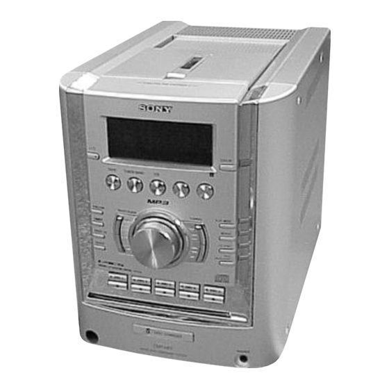
HCD-HP7 is the Amplifier, CD player, Tape
Deck and Tuner section in CMT-HP7.
Main unit
AUDIO POWER SPECIFICATIONS
POWER OUTPUT AND TOTAL HARMONIC
DISTORTION:
With 6 ohm loads, both channels driven, from
120 – 10,000 Hz: rated 60 watts per channel
minimum RMS power, with no more than 10%
total harmonic distortion from 250 milliwatts to
rated output.
Amplifier section
North American model:
Continuous RMS power output (reference):
60 + 60 watts (6 ohms at 1
kHz, 10% THD)
Total harmonic distortion less than 0.7% (6 ohms at 1
kHz, 30 W)
European and Russian models:
DIN power output (rated): 60 + 60 watts (6 ohms at 1
kHz, DIN)
Continuous RMS power output (reference):
60 + 60 watts (6 ohms at 1
kHz, 10% THD)
Music power output (reference):
120 + 120 watts (6 ohms at
1 kHz, 10% THD)
Sony Corporation
9-877-349-02
2003K16-1
Home Audio Company
© 2003.11
Published by Sony Engineering Corporation
Model Name Using Similar Mechanism
CD Mechanism Type
CD
Section
Base Unit Name
Optical Pick-up Name
Model Name Using Similar Mechanism
TAPE
Section
Tape Transport Mechanism Type
SPECIFICATIONS
Other models:
The following measured at AC 120, 127, 220, 240 V
50/60 Hz
DIN power output (rated): 60 + 60 watts (6 ohms at 1
kHz, DIN)
Continuous RMS power output (reference):
60 + 60 watts (6 ohms at 1
kHz, 10% THD)
Inputs
MD IN (phono jacks):
Sensitivity 250 mV,
impedance 47 kilohms
Outputs
PHONES (stereo minijack):
accepts headphones of 8
ohms or more
OPTICAL CD DIGITAL OUT (Supported sampling
frequency: 44.1 kHz)
SPEAKER:
accepts impedance of 6 to
16 ohms.
MICRO HI-FI COMPONENT SYSTEM
HCD-HP7
Canadian Model
Australian Model
CD player section
System
Laser
Frequency response
Wavelength
Signal-to-noise ratio
Dynamic range
Tape deck section
Recording system
Frequency response
US Model
AEP Model
UK Model
E Model
NEW
CDM69CH-K6BD71C
BU-K6BD71C
KSM-213D
HCD-EP515
CMAL1Z234A
Compact disc and digital
audio system
Semiconductor laser
λ
(
=780 nm)
Emission duration:
continuous
2 Hz – 20 kHz (±0.5 dB)
780 – 790 nm
More than 90 dB
More than 90 dB
4-track 2-channel, stereo
50 – 13,000 Hz (±3 dB),
using Sony TYPE I
cassettes
Advertisement
Table of Contents

Related Manuals for Sony HCD-HP7


Summary of Contents for Sony HCD-HP7
- Page 1 Canadian Model Ver 1.1 2003. 11 AEP Model UK Model E Model Australian Model HCD-HP7 is the Amplifier, CD player, Tape Deck and Tuner section in CMT-HP7. Model Name Using Similar Mechanism CD Mechanism Type CDM69CH-K6BD71C Section Base Unit Name...
- Page 2 CRITIQUES POUR LA SÉCURITÉ DE FONCTIONNEMENT. NE COMPONENTS WITH SONY PARTS WHOSE PART NUMBERS REMPLACER CES COMPOSANTS QUE PAR DES PIÈSES SONY APPEAR AS SHOWN IN THIS MANUAL OR IN SUPPLEMENTS DONT LES NUMÉROS SONT DONNÉS DANS CE MANUEL OU PUBLISHED BY SONY.
-
Page 3: Table Of Contents
HCD-HP7 Ver 1.1 2003.11 TABLE OF CONTENTS 1. SERVICING NOTES 6. MECHANICAL ADJUSTMENTS ······················································· 4 ····························· 23 7. ELECTRICAL ADJUSTMENTS 2. GENERAL ······························· 24 ·········································································· 6 8. DIAGRAMS ······································································ 26 3. DISASSEMBLY 8-1. Block Diagram ···························································· 28 3-1. Case (Side-L)(Side-R), 8-2. -
Page 4: Servicing Notes
HCD-HP7 SECTION 1 SERVICING NOTES Notes on chip component replacement CAUTION • Never reuse a disconnected chip component. Use of controls or adjustments or performance of procedures • Notice that the minus side of a tantalum capacitor may be dam- other than those specified herein may result in hazardous aged by heat. - Page 5 HCD-HP7 Service Position of the Tape Cassette Mechanism Deck Service Position of the CD Mechanism Deck Connect jig (extension cable J-2501-248-A) to the MAIN board (CN302) and CONNECTOR board (CN701). Connect jig (extension cable J-2501-011-B) to the MAIN board (CN301) and BD board (CN710).
-
Page 6: General
HCD-HP7 SECTION 2 GENERAL This section is extracted from instruction manual. List of button locations and reference pages Main unit BUTTON DESCRIPTIONS ALPHABETICAL ORDER ?/1 (power) 1 (7, 8, 14, 20, 21, P – Z A – G PHONES jack qd... -
Page 7: Setting The Clock
HCD-HP7 Remote control ALPHABETICAL ORDER BUTTON DESCRIPTIONS ?/1 (power) 4 (7, 8, 20, 21, 29) A – G I – Z m/M (rewind/fast forward) ALBUM +/– qf (10, 11) ILLUMINATION* 5 (10, 16) CD ql (9, 11, 17) PLAY MODE w; (9, 11, 16, 17, ./>... -
Page 8: Disassembly
HCD-HP7 Ver 1.1 2003.11 SECTION 3 DISASSEMBLY • This set can be disassembled in the order shown below. CASE (SIDE-L) (SIDE-R), TAPE MECHANISM DECK (CMAL1Z234A)) BACK PANEL SECTION FRONT PANEL SECTION MAIN BOARD PANEL BOARD PWR AMP BOARD, POWER TRANSFORMER... -
Page 9: Case (Side-L)(Side-R), Tape Mechanism Deck (Cmal1Z234A)
HCD-HP7 Note: Follow the disassembly procedure in the numerical order given. 3-1. Case (Side-L)(Side-R), Tape Mechanism Deck (CMAL1Z234A) 7 two screws 8 top panel section (BVTP3 × 16 ) 5 two screws (BVTP3 × 16 ) 4 four screws qd tape mechanism deck... -
Page 10: Panel Board
HCD-HP7 3-3. Panel Board 4 PANEL board 3 six claws 2 ten screws (BVTP2.6 × 8) 1 knob (VOL) 3-4. Back Panel Section 6 connector 8 back panel section (CN908) 2 four screws (BVTP3 × 10 ) 4 connector (CN503) 3 two screws (BVTP3 ×... -
Page 11: Main Board
HCD-HP7 3-5. MAIN Board 5 w ire (flat type) 9p (CN303) 4 w ire (flat type) 37p (CN402) 3 connector (CN404) 1 connector (CN907) 9 MAIN board 2 two screws (BVTP3 × 8) 8 connector 7 w ire (flat type) -
Page 12: Cd Mechanism Deck (Cdm69Ch-K6Bd71C)
HCD-HP7 3-7. CD Mechanism Deck (CDM69CH-K6BD71C) 1 two screws (BVTP3 × 8 ) 3 blacket (TR) 2 two screws (BVTP3 × 8 ) 4 four screws (BVTP3 × 8 ) 7 CD mechanism deck 5 w ire (flat type) (CDM69CH-K6BD71C) -
Page 13: Base Unit (Bu-K6Bd71C)
HCD-HP7 3-9. Base Unit (BU-K6BD71C) 3 floating screw (+PTPWHM2.6) 8 insulator (213) q; base unit (BU-K6BD71C) 4 floating screw 2 floating screw (+PTPWHM2.6) (+PTPWHM2.6) 7 insulator (213) 9 insulator (213) 1 floating screw (+PTPWHM2.6) 6 insulator (213) 3-10. BD Board 2 Remove the solder (four portions). -
Page 14: Sw Board, Bracket (Top) Assy
HCD-HP7 Ver 1.1 2003.11 3-12. SW Board, Bracket (Top) Assy 4 SW (3) board 5 SW (4) board 3 SW (2) board 1 four screws (BTP2.6 × 6) 6 six screws (BVTP2.6 × 8) 2 SW (1) board 7 bracket (top) assy... -
Page 15: Connector Board
HCD-HP7 3-13. CONNECTOR Board 4 connector (CN710) 5 connector (CN702) – bottom view – 6 connector (CN703) CONNECTOR board 2 four screws (BVTP2.6 × 8) 7 CONNECTOR board 1 Remove five solders. 3-14. Motor (Stocker) Assy (Stocker)(M761) 3 two screws (BVTP2.6 ×... -
Page 16: Motor (Roller) Assy (Roller)(M781)
HCD-HP7 3-15. Motor (Roller) Assy (Roller)(M781) 3 two screws 2 Remove two solders. 4 ROLLER MOTOR board 5 motor (roller) assy (roller)(M781) 1 belt (roller V) 3-16. Motor (Mode) Assy (Mode)(M771) 3 two screws (BVTP2.6 × 8) 1 Remove five solders of rotary encoder. -
Page 17: Rubber Roller (Slider) Assy
HCD-HP7 3-17. Rubber Roller (Slider) Assy 8 step screw 5 step screw 1 step screw 9 tension spring 0 rubber roller (slider 2) 6 tension spring (slider 1) assy (base slider 4) 2 rubber roller (slider S) assy qa rubber roller... -
Page 18: Cam (Gear)
HCD-HP7 3-19. Cam (Gear) qf cam (gear) : Note 6 gear (mode 5) qd screw 5 screw (PTPWH2.6 × 8) 4 gear (mode 5) qs gear(mode cam) 3 screw (PTPWH2.6 × 8) qa screw (PTPWH2.6 × 8) 2 pulley (mode deceleration) -
Page 19: Assembly
HCD-HP7 SECTION 4 ASSEMBLY • This set can be assembled in the order shown below. 4-1. How to Install the Cam (Eject Lock) 1 Rotate the cam (BU U/D) fully in the direction of arrow. 2 Engage the gear (eject lock) and the gear of the cam (eject lock) aligning the mark with the center of the gear (eject lock). -
Page 20: How To Install The Gear (Mode C)
HCD-HP7 4-3. How to Install the Gear (Mode C) 1 Align the mark on the rotary encoder (S771) with the projection of the assy. 2 Check that the cam (BU U/D) can not be rotated in the direction of arrow. - Page 21 HCD-HP7 4-5. How to Install the Rotary Encoder (S702), Gear (Stocker Communication) 4 gear 5 screw (PTPWH2.6 × 8) (stocker communication) 3 screw 7 two screws (PWH2 × 6) (PTPWH2.6 × 8) 1 rotary encoder Engage the rotary encoder (S702)
-
Page 22: Test Mode
HCD-HP7 SECTION 5 TEST MODE [AM Channel Step 9 kHz/10kHz Selection Mode] [Panel Test Mode] * Either the 9 kHz step or 10 kHz step can be selected for the AM * All fluorecent segments, LEDs, keys, volume and headphone channel step. -
Page 23: Mechanical Adjustments
HCD-HP7 SECTION 6 MECHANICAL ADJUSTMENTS • TAPE MECHANISM DECK SECTION [AMP Test Mode] Precaution Procedure: 1. Clean the following parts with a denatured alcohol-moistened Press the ?/1 button to turn the set on. swab: To enter the test mode, press the three buttons x ,... -
Page 24: Electrical Adjustments
HCD-HP7 SECTION 7 ELECTRICAL ADJUSTMENTS Mode: Playback DECK SECTION 0 dB=0.775 V Note: Confirm each contents of this section first of all. If the results are PWR AMP board not satisfied, do the adjustment. SPEAKER terminals (JK501) test tape Demagnetize the record/playback head with a head... - Page 25 HCD-HP7 CD SECTION Checking Location: – BD BOARD (Conductor Side) – Note: CD Block is basically constructed to operate without adjustment. Use YEDS-18 disc (3-702-101-01) unless otherwise indicated. Use an oscilloscope with more than 10 MΩ impedance. Clean the object lens by an applicator with neutral detergent when the signal level is low than specified value with the following checks.
-
Page 26: Diagrams
HCD-HP7 SECTION 8 DIAGRAMS • Circuit Boards Location SUB TRANS board SENSOR (FAN) board PWR TRANS board PWR AMP board MAIN board PANEL board ROLLER MOTOR board STOCKER MOTOR board SW (4) board ST ENCODER board SW (3) board SW (2) board... - Page 27 HCD-HP7 • Waveforms THIS NOTE IS COMMON FOR PRINTED WIRING For printed wiring boards. – BD Board – – PANEL Board – – MAIN Board – Note: BOARDS AND SCHEMATIC DIAGRAMS. • X : parts extracted from the component side.
-
Page 28: Block Diagram
HCD-HP7 Ver 1.1 2003.11 8-1. Block Diagram POWER AMP SOUND PROCESSOR IC501 JK301 IC301 R CH JK601 IND2 OUT2 PHONES INB2 DBFB MUTE PROTECT R-CH INA2 Q301 Q304 DETECT INC2 Q507,508 RECB2 VACS TUNER PACK D417 SA OUT Q609,610 +10V... -
Page 29: Printed Wiring Boards - Bd Board
HCD-HP7 Ver 1.1 2003.11 8-2. Printed Wiring Boards — BD Board — • : Uses unleaded solder. • See page 26 for Circuit Boards Location. BD BOARD (COMPONENT SIDE) OPTICAL BD BOARD PICK-UP BLOCK (CONDUCTOR SIDE) M702 (KSM-213D) • Semiconductor... -
Page 30: Schematic Diagram - Bd Board
HCD-HP7 Ver 1.1 2003.11 8-3. Schematic Diagram — BD Board — • See page 39, 40 for IC Block Diagrams. • See page 27 for Waveforms. R732 IC803 R731 R721 R722 C753 R834 R707 C709 C746 C742 C708 R729 C744... -
Page 31: Printed Wiring Boards - Changer Section
HCD-HP7 8-4. Printed Wiring Boards — Changer Section — • : Uses unleaded solder. • See page 26 for Circuit Boards Location. • Semiconductor Location Ref. No. Location D701 MAIN BOARD D711 CN302 D721 (Page 33) IC701 IC711 IC721 IC751... -
Page 32: Schematic Diagram - Changer Section
HCD-HP7 8-5. Schematic Diagram — Changer Section — • See page 41 for IC Block Diagrams. CN751 CN702 R731 DIODE DIODE I C 7 5 1 D SENSE D SENSE R733 CN701 R734 IC751 D+3.3V 3 . 2 RPR-220 R732... -
Page 33: Printed Wiring Boards - Main Section
HCD-HP7 8-6. Printed Wiring Boards — Main Section — • : Uses unleaded solder. • See page 26 for Circuit Boards Location. • Semiconductor Location Ref. No. Location D101 D102 D301 D302 D303 D304 D305 D306 D307 D309 D401 (AEP,UK) -
Page 34: Schematic Diagram - Main Section
HCD-HP7 8-7. Schematic Diagram — Main Section — • See page 41 for IC Block Diagrams. • See page 27 for Waveforms. CONNECTOR BOARD CN701 (Page 32) MAIN BOARD ANTENNA FM75Ω COAXIAL CN101 15P:AEP,UK 11P:EXCEPT AEP,UK AEP,UK R101,102 47K:AEP,UK IC302... -
Page 35: Printed Wiring Boards - Front Section
HCD-HP7 8-8. Printed Wiring Boards — Front Section — • : Uses unleaded solder. • See page 26 for Circuit Boards Location. MAIN BOARD PANEL BOARD CN303 (Page 33) • Semiconductor Location (EXCEPT AEP,UK,RU) Ref. No. Location (AEP,UK,RU) S627 D606... -
Page 36: Schematic Diagram - Front Section
HCD-HP7 8-9. Schematic Diagram — Front Section — • See page 40 for IC Block Diagrams. • See page 27 for Waveforms. MAIN BOARD CN303 (Page34 ) PANEL BOARD (FLUORESCENT INDICATOR TUBE) PHONES MAIN VACS BOARD CN305 (Page34 ) VACS -26.4... -
Page 37: Printed Wiring Boards - Pwr Amp/Power Section
HCD-HP7 8-10. Printed Wiring Boards — PWR AMP/Power Section — • : Uses unleaded solder. • See page 26 for Circuit Boards Location. PWR TRANS BOARD SUB TRANS BOARD T901 POWER TRANSFORMER (MAIN) (US,CND) (E2,E3,TW) CN906 (E2,E3,TW) 4P : E2,E3,TW... -
Page 38: Schematic Diagram - Pwr Amp/Power Section
HCD-HP7 8-11. Schematic Diagram — PWR AMP/Power Section — • See page 41 for IC Block Diagrams. SPEAKER IMPEADANCE USE 6-16Ω 14.3 C516 4.7K PWR TRANS BOARD FAN DRIVE C528 0.1U 0.22U 0.22U POWER TRANSFORMER JR503 JR502 C531 (MAIN) 14.4 Q507,508 PROTECT DETECT 4.7K... -
Page 39: Ic Block Diagrams
HCD-HP7 8-12. IC Block Diagrams — BD Board — IC721 LC78646E-E 78 77 76 75 74 73 72 71 69 68 67 66 65 64 63 62 61 FIN1 – FIN2 – TIN1 TBAL – – TIN2 – – TBAL –... - Page 40 HCD-HP7 IC801 LC78684E-E 60-53 50-46 DVDD5 DATA-I/F STREQ MDATA15 STCK DRAM-I/F MDATA8 STDAT DECODER FSYNC CRCF CDROM DVDD6 DECODER CD-DA SHOCKPROOF (COMPRESSED OR UNCOMPRESSED) DVDD3 CNTOK CMDOUT AUDIO-I/F CMDIN CPU-I/F MDATA7 SYSTEM CLOCK MDATA0 GENERATOR INTB RESB DATAIN DATACK DVDD2 —...
- Page 41 HCD-HP7 — MAIN Board — IC201 HA12237F — PWR AMP Board — IC501 STK403-070S PRE DRIVER PRE DRIVER BIAS CIRCUIT 5 6 7 8 9 10 11 13 14 — CONNECTOR Board — IC701, 711, 721 BA6956AN CONTROL LOGIC...
-
Page 42: Ic Pin Function Description
HCD-HP7 8-13. IC Pin Function Description • IC601 LC876796B-51K7-E (SYSTEM CONTROLLER)(PANEL B0ARD) Pin No. Pin Name Description SYS MUTE System muting signal output BU1924 DATA RDS data input from the tuner CD POWER Not used (open) LC87646 RESET Reset signal output to the RF amplifier (IC721) - Page 43 HCD-HP7 Pin No. Pin Name Description VR ENCODER B Volume signal input from the rotary encoder (VR601) CDM D.SENSOR Disc detection signal input PROTECTOR Protection signal input from the power amplifier circuit TAPE END Tape end detection signal input from the tape deck...
-
Page 44: Exploded Views
HCD-HP7 SECTION 9 EXPLODED VIEWS NOTE: • -XX, -X mean standardized parts, so they may • Abbreviation The components identified by mark 0 or have some differences from the original one. AUS : Australian model. dotted line with mark 0 are critical for safety. -
Page 45: Front Panel Section
HCD-HP7 9-2. Front Panel Section Ref. No. Part No. Description Remark Ref. No. Part No. Description Remark 4-225-252-01 CUSHION (FOOT) 1-769-920-11 WIRE (FLAT TYPE)(9 CORE) 4-246-397-01 EMBLEM (5CD) A-4734-337-A PANEL BOARD, COMPLETE (US,CND) 4-246-384-01 KNOB (VOL) A-4734-349-A PANEL BOARD, COMPLETE (AEP,UK,RU) -
Page 46: Chassis Section-1
HCD-HP7 Ver 1.1 2003.11 9-3. Chassis Section-1 supplied T901 supplied F904 F905 F903 F902 F901 chassis section Ref. No. Part No. Description Remark Ref. No. Part No. Description Remark 0 F902 1-689-250-11 PWR TRANS BOARD 1-533-473-11 FUSE, GLASS TUBE (DIA. 5)(T6.3AL/250V) -
Page 47: Chassis Section-2
HCD-HP7 9-4. Chassis Section-2 supplied supplied CD mechanism deck section-1 supplied Ref. No. Part No. Description Remark Ref. No. Part No. Description Remark 0 151 1-690-608-11 CORD, POWER (AUS) * 152 3-703-244-00 BUSHING (2104), CORD (EXCEPT E2,E3,MX) 0 151 1-769-079-22 CORD, POWER (KR) -
Page 48: Cd Mechanism Section-1 (Cdm69Ch-K6Bd71C)
HCD-HP7 9-5. CD Mechanism Section-1 (CDM69CH-K6BD71C) not supplied S702 M761 supplied not supplied CD mechanism deck section-2 Ref. No. Part No. Description Remark Ref. No. Part No. Description Remark 1-686-725-12 STOCKER MOTOR BOARD 4-239-698-01 PULLEY (STOCKER) 4-951-620-01 SCREW (2.6X8), +BVTP... -
Page 49: Cd Mechanism Section-2 (Cdm69Ch-K6Bd71C)
HCD-HP7 9-6. CD Mechanism Section-2 (CDM69CH-K6BD71C) CD mechanism deck section-3 CD mechanism deck section-4 optical pick-up section Ref. No. Part No. Description Remark Ref. No. Part No. Description Remark 1-686-727-12 SW (1) BOARD 4-951-620-01 SCREW (2.6X8), +BVTP 1-686-728-12 SW (2) BOARD 4-985-672-01 SCREW (+PTPWHM2.6), FLOATING... -
Page 50: Cd Mechanism Section-3 (Cdm69Ch-K6Bd71C)
HCD-HP7 9-7. CD Mechanism Section-3 (CDM69CH-K6BD71C) not supplied supplied not supplied supplied supplied not supplied Ref. No. Part No. Description Remark Ref. No. Part No. Description Remark X-4955-448-1 PULLEY(A)(KSM213)ASSY,CHUCKING 4-243-291-01 SPRING, TORSION 4-992-069-01 SCREW (+PTPWH)(M2)(DIA. 7) 4-240-039-01 LEVER (DISC STOPPER) -
Page 51: Cd Mechanism Section-4 (Cdm69Ch-K6Bd71C)
HCD-HP7 9-8. CD Mechanism Section-4 (CDM69CH-K6BD71C) supplied supplied M781 CD mechanism deck section-5 Ref. No. Part No. Description Remark Ref. No. Part No. Description Remark X-4954-626-1 LEVER (ROLLER) ASSY 4-240-041-01 SPRING (SLIDER 2), TENSION 4-239-666-01 GEAR 4-951-620-01 SCREW (2.6X8), +BVTP... -
Page 52: Cd Mechanism Section-5 (Cdm69Ch-K6Bd71C)
HCD-HP7 9-9. CD Mechanism Section-5 (CDM69CH-K6BD71C) CD mechanism sdeck ection-6 Ref. No. Part No. Description Remark Ref. No. Part No. Description Remark 4-240-020-01 GEAR (TIMING) 4-239-699-01 PULLEY 4-239-708-02 BELT (FRONT), TIMING 4-247-349-02 BELT (ROLLER V) 4-239-697-01 GEAR (CENTER) 4-227-899-01 SCREW (DIA. 12), FROATING... -
Page 53: Cd Mechanism Section-6 (Cdm69Ch-K6Bd71C)
HCD-HP7 9-10. CD Mechanism Section-6 (CDM69CH-K6BD71C) M771 not supplied supplied supplied S771 Ref. No. Part No. Description Remark Ref. No. Part No. Description Remark 4-239-693-02 CAM (GEAR) 4-239-694-01 GEAR (MODE CAM) 1-686-723-12 SENSOR BOARD 4-241-731-01 SHUTTER (A), LEVER 4-239-696-01 GEAR (EJECT LOCK) -
Page 54: Optical Pick-Up Section (Ksm-213D)
HCD-HP7 Ver 1.1 2003.11 9-11. Optical Pick-up Section (KSM-213D) not supplied Ref. No. Part No. Description Remark Ref. No. Part No. Description Remark 4-229-806-01 SPRING (213), COMPRESSION 4-985-672-01 SCREW (+PTPWHM2.6), FLOATING A-4747-707-A BD BOARD, COMPLETE 0 607 A-4735-357-A BASE ASSY, OP (KSM-213D) 4-227-679-01 INSULATOR (213) 7-685-534-19 SCREW +BTP 2.6X8 TYPE2 N-S... -
Page 55: Electrical Parts List
HCD-HP7 Ver 1.1 2003.11 SECTION 10 ELECTRICAL PARTS LIST NOTE: • Due to standardization, replacements in the • RESISTORS MX : Mexican model. parts list may be different from the parts All resistors are in ohms. RU : Russian model. - Page 56 HCD-HP7 Ver 1.1 2003.11 CONNECTOR Ref. No. Part No. Description Remarks Ref. No. Part No. Description Remarks FB805 1-550-907-21 BEAD, FERRITE (CHIP) R803 1-216-809-11 METAL CHIP 1/10W FB806 1-550-907-21 BEAD, FERRITE (CHIP) R804 1-216-809-11 METAL CHIP 1/10W FB807 1-550-907-21 BEAD, FERRITE (CHIP)
- Page 57 HCD-HP7 CONNECTOR MAIN Ref. No. Part No. Description Remarks Ref. No. Part No. Description Remarks < DIODE > C224 1-126-963-11 ELECT 4.7uF 20.00% 50V C225 1-126-933-11 ELECT 100uF 20.00% 16V D701 8-719-921-40 DIODE MTZJ-T-77-4.7B D711 8-719-109-89 DIODE MTZJ-T-77-5.6B C226 1-126-963-11 ELECT 4.7uF...
- Page 58 HCD-HP7 MAIN Ref. No. Part No. Description Remarks Ref. No. Part No. Description Remarks C352 1-162-964-11 CERAMIC CHIP 0.001uF D403 6-500-522-21 DIODE 10EDB40-TB3 C353 1-162-962-11 CERAMIC CHIP 470PF D404 6-500-522-21 DIODE 10EDB40-TB3 C354 1-162-962-11 CERAMIC CHIP 470PF D405 6-500-522-21 DIODE 10EDB40-TB3...
- Page 59 HCD-HP7 MAIN Ref. No. Part No. Description Remarks Ref. No. Part No. Description Remarks L301 1-410-521-11 INDUCTOR 100uH R219 1-216-813-11 METAL CHIP 1/10W R220 1-216-821-11 METAL CHIP 1/10W < IC > R221 1-216-841-11 METAL CHIP 1/10W R222 1-216-841-11 METAL CHIP...
- Page 60 HCD-HP7 MAIN MODE MOTOR PANEL Ref. No. Part No. Description Remarks Ref. No. Part No. Description Remarks R343 1-216-829-11 METAL CHIP 4.7K 1/10W R427 1-218-717-11 METAL CHIP 1/10W R344 1-216-837-11 METAL CHIP 1/10W R428 1-218-717-11 METAL CHIP 1/10W R429 1-216-837-11 METAL CHIP...
- Page 61 HCD-HP7 PANEL Ref. No. Part No. Description Remarks Ref. No. Part No. Description Remarks C617 1-162-961-11 CERAMIC CHIP 330PF < JUMPER RESISTOR > C618 1-164-156-11 CERAMIC CHIP 0.1uF C619 1-128-551-11 ELECT 22uF 20.00% 25V JR605 1-216-864-11 METAL CHIP 1/10W C620 1-164-156-11 CERAMIC CHIP 0.1uF...
- Page 62 HCD-HP7 PANEL Ref. No. Part No. Description Remarks Ref. No. Part No. Description Remarks R083 1-216-841-11 METAL CHIP 1/10W R656 1-216-841-11 METAL CHIP 1/10W R084 1-216-841-11 METAL CHIP 1/10W R657 1-216-829-11 METAL CHIP 4.7K 1/10W R085 1-216-841-11 METAL CHIP 1/10W...
- Page 63 HCD-HP7 PANEL PWR AMP Ref. No. Part No. Description Remarks Ref. No. Part No. Description Remarks S606 1-762-196-21 SWITCH,TACT (DISC 5 Z) C524 1-164-156-11 CERAMIC CHIP 0.1uF S607 1-762-196-21 SWITCH,TACT (DISC 4 Z) C525 1-164-156-11 CERAMIC CHIP 0.1uF S608 1-762-196-21 SWITCH,TACT (DISC 3 Z)
- Page 64 HCD-HP7 PWR AMP PWR TRANS ROLLER MOTOR SENSOR SENSOR (FAN) ST ENCODER Ref. No. Part No. Description Remarks Ref. No. Part No. Description Remarks < TRANSISTOR > R546 1-216-839-11 METAL CHIP 1/10W R547 1-216-833-11 METAL CHIP 1/10W Q501 8-729-120-28 TRANSISTOR...
- Page 65 HCD-HP7 Ver 1.1 2003.11 STOCKER MOTOR SUB TURANS SW (1) SW (2) SW (3) SW (4) Ref. No. Part No. Description Remarks Ref. No. Part No. Description Remarks 1-686-725-12 STOCKER MOTOR BOARD S717 1-786-382-11 SWITCH,PUSH (1 KEY)(DISC POSITION) S718 1-786-382-11 SWITCH,PUSH (1 KEY)(STOCKING)
- Page 66 HCD-HP7 REVISION HISTORY Clicking the version allows you to jump to the revised page. Also, clicking the version at the upper right on the revised page allows you to jump to the next revised page. Ver. Date Description of Revision 2003.06...