Asus M4N78 PRO - Motherboard - ATX User Manual
Nvidia geforce 8300 chipset
Hide thumbs
Also See for M4N78 PRO - Motherboard - ATX:
- User manual (44 pages) ,
- User manual (60 pages)
Table of Contents
Advertisement
Advertisement
Table of Contents

Related Manuals for Asus M4N78 PRO - Motherboard - ATX


Summary of Contents for Asus M4N78 PRO - Motherboard - ATX
- Page 1 M4N78 PRO...
- Page 2 Product warranty or service will not be extended if: (1) the product is repaired, modified or altered, unless such repair, modification of alteration is authorized in writing by ASUS; or (2) the serial number of the product is defaced or missing.
-
Page 3: Table Of Contents
Contents Contents ...................... iii Notices ......................v Safety information ..................vi About this guide ..................vi M4N78 PRO specifications summary ............. viii Chapter 1 Product introduction Welcome! ..................1-1 Package contents ................. 1-1 Special features ................1-1 Before you proceed ..............1-3 Motherboard overview .............. -
Page 4: Contents
2.5.5 USB Configuration ............2-21 Power menu ................2-22 Boot menu .................. 2-24 Tools menu ................. 2-26 2.8.1 ASUS EZ Flash 2 ............2-26 2.8.2 Express Gate [Enabled] ..........2-26 2.8.3 ASUS O.C. Profile ............2-27 2.8.4 AI NET 2................ 2-27... -
Page 5: Notices
Notices Federal Communications Commission Statement This device complies with Part 15 of the FCC Rules. Operation is subject to the following two conditions: • This device may not cause harmful interference, and • This device must accept any interference received including interference that may cause undesired operation. -
Page 6: Safety Information
Safety information Electrical safety • To prevent electrical shock hazard, disconnect the power cable from the electrical outlet before relocating the system. • When adding or removing devices to or from the system, ensure that the power cables for the devices are unplugged before the signal cables are connected. If possible, disconnect all power cables from the existing system before you add a device. -
Page 7: Conventions Used In This Guide
Refer to the following sources for additional information and for product and software updates. ASUS websites The ASUS website provides updated information on ASUS hardware and software products. Refer to the ASUS contact information. Optional documentation Your product package may include optional documentation, such as warranty flyers, that may have been added by your dealer. -
Page 8: M4N78 Pro Specifications Summary
*Due to AMD CPU limitation, DDR2 1066 is supported by AM2+ / AM3 CPUs for one DIMM per channel only. Refer to www.asus.com or this user manual for the Memory QVL (Qualified Vendors Lists). ** Due to OS limitation, when installing total memory of 4GB capacity or more, Windows 32-bit operation system may only recognize less than 3GB. - Page 9 - ASUS Anti-Surge Protection Express Gate ASUS Green Design: - ASUS EPU* - ASUS AI Nap *ASUS EPU is supported by AM3/AM2+ CPU only. ASUS Quiet Thermal Solution: - ASUS Fanless Design: Stylish heatsink solution - ASUS Q-Fan 2 ASUS Crystal Sound:...
- Page 10 1 x 4-pin ATX 12V Power connector 1 x System Panel (Q-Connector) 8 Mb Flash ROM, AMI BIOS, PnP, DMI 2.0, WfM2.0, BIOS features SM BIOS 2.5, ACPI 2.0, ASUS EZ Flash 2 Support DVD contents Drivers Express Gate ASUS PC Probe II...
-
Page 11: Chapter 1 Product Introduction
® The motherboard delivers a host of new features and latest technologies, making it another standout in the long line of ASUS quality motherboards! Before you start installing the motherboard, and hardware devices on it, check the items in your package with the list below. -
Page 12: Innovative Asus Features
Unleashes ultimate memory performances with independent power to core components, while providing fast transient response and stability for the CPU under heavy loading or overclocking modes. ASUS M4N78 PRO also features an extra 1 phase power dedicated to integrated memory/HT controller. -
Page 13: Before You Proceed
TurboV provides the best O.C. settings in different scenarios. ASUS Turbo Key ASUS Turbo Key allows the user to turn the PC power button into an overclocking button. After the easy setup, Turbo Key can boost performances without interrupting ongoing work or games—with just one touch! -
Page 14: Motherboard Overview
Place nine (9) screws into the holes indicated by circles to secure the motherboard to the chassis. Do not overtighten the screws! Doing so can damage the motherboard. Place this side towards the rear of the chassis. ASUS M4N78 PRO... -
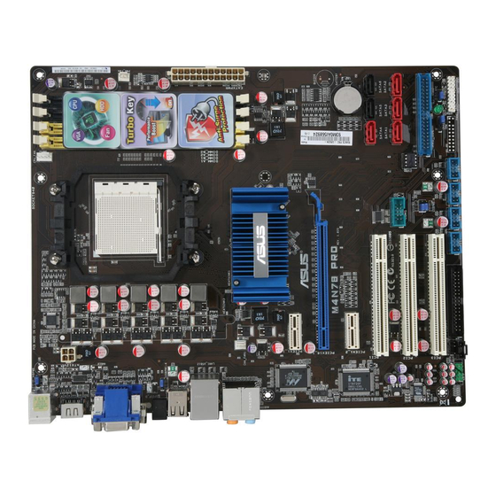
Page 15: Motherboard Layout
1.5.3 Motherboard layout 1.5.4 Layout contents Connectors/Jumpers/Slots Page Keyboard power (3-pin KBPWR) 1-15 1-20 ATX power connectors (24-pin EATXPWR, 4-pin ATX12V) CPU socket AM2+/AM2 1-19 CPU, Chassis and Power Fan connectors (4-pin CPU_FAN, 3-pin CHA_FAN1, 3-pin PWR_FAN) DDR2 DIMM slots Serial ATA connectors (7-pin SATA1-6) 1-22 1-21... -
Page 16: Central Processing Unit (Cpu)
Carefully insert the CPU into the socket until it fits in place. The CPU fits only in one correct orientation. DO NOT force the CPU into the socket to prevent bending the pins and damaging the CPU! Small triangle Gold triangle ASUS M4N78 PRO... -
Page 17: Installing The Heatsink And Fan
When the CPU is in place, push down the socket lever to secure the CPU. The lever clicks on the side tab to indicate that it is locked. Install a CPU heatsink and fan following the instructions that came with the heatsink package. You can also refer to section 1.6.2 Installing heatsink and fan for instructions. - Page 18 When the fan and heatsink assembly is in place, connect the CPU fan cable to the connector on the motherboard labeled CPU_FAN. Do not forget to connect the CPU fan connector! Hardware monitoring errors can occur if you fail to plug this connector. ASUS M4N78 PRO...
-
Page 19: System Memory
System memory 1.7.1 Overview The motherboard comes with two Double Data Rate 2 (DDR2) Dual Inline Memory Modules (DIMM) sockets. A DDR2 module has the same physical dimensions as a DDR DIMM but has a 240-pin footprint compared to the 184-pin DDR DIMM. DDR2 DIMMs are notched differently to prevent installation on a DDR DIMM socket. - Page 20 GEIL Heat-Sink Package 2048MB GEIL GE24GB800C4DC • • • GEIL Heat-Sink Package 2048MB GEIL GE24GB800C5DC • • • GEIL Heat-Sink Package 2048MB GEIL GE28GB800C4QC • • • GEIL Heat-Sink Package 2048MB GEIL GE28GB800C5QC • • • ASUS M4N78 PRO 1-10...
- Page 21 DDR2-800MHz capability Timing DIMM socket Vendor Part No. Size Chip Brand Chip NO. Dimm Voltage support (Optional) (Bios) • • • GEIL Heat-Sink Package 2048MB GEIL GX24GB6400DC HY5PS12821CFP-S5 512MB Hynix HYMP564U64CP8-S5 AB • • • HY5PS12821CFPS5 1024MB Hynix HYMP 512U64CP8-S5 AB •...
- Page 22 • B*: Supports two modules inserted into either the yellow slots or the black slots as one pair of Dual-channel memory configuration. • C*: Supports four modules inserted into both the yellow slots and the black slots as two pairs of Dual-channel memory configuration. Visit the ASUS website for the latest QVL. ASUS M4N78 PRO 1-12...
-
Page 23: Installing A Dimm
1.7.3 Installing a DIMM Unplug the power supply before adding or removing DIMMs or other system components. Failure to do so can cause severe damage to both the motherboard and the components. Press the retaining clips outward to DDR2 DIMM notch unlock a DDR2 DIMM socket. -
Page 24: Expansion Slots
This motherboard supports PCI Express x1 network cards, SCSI cards, and other cards that comply with the PCI Express specifications. 1.8.5 PCI Express x16 slot This motherboard supports a PCI Express x16 graphics card that complies with the PCI Express specifications. ASUS M4N78 PRO 1-14... -
Page 25: Jumpers
Jumpers Clear RTC RAM (CLRTC) This jumper allows you to clear the Real Time Clock (RTC) RAM in CMOS. You can clear the CMOS memory of date, time, and system setup parameters by erasing the CMOS RTC RAM data. The onboard button cell battery powers the RAM data in CMOS, which include system... -
Page 26: Connectors
LAN port LED indications Right Left Status Left LED Right LED Orange (blinking during 10 Mbps connection data activity) 100 Mbps connection Orange (blinking during data activity) 1 Gbps connection Green (blinking during data activity) LAN port ASUS M4N78 PRO 1-16... - Page 27 Center/Subwoofer port (orange). This port connects the center/subwoofer speakers. Rear Speaker Out port (black). This port connects the rear speakers in a 4-channel, 6-channel, or 8-channel audio configuration. Line In port (light blue). This port connects the tape, CD, DVD player, or other audio sources.
-
Page 28: Internal Connectors
HDTV compliance resolution such as 480i, 720i, or 1080i. 1.10.2 Internal connectors Optical drive audio in connector (4-pin CD) This connector allows you to receive stereo audio input from sound sources such as a CD-ROM, TV tuner, or MPEG card. ASUS M4N78 PRO 1-18... - Page 29 These are not jumpers! DO NOT place jumper caps on the fan connectors. Only the CPU_FAN and CHA_FAN1 connectors support the ASUS Q FAN 2 feature. Chassis intrusion connector (4-1 pin CHASSIS) This connector is for a chassis-mounted intrusion detection sensor or switch. Connect one end of the chassis intrusion sensor or switch cable to this connector.
- Page 30 The system may become unstable or may not boot up if the power is inadequate. • If you are uncertain about the minimum power supply requirement for your system, refer to the Recommended Power Supply Wattage Calculator at http://support.asus. com/PowerSupplyCalculator/PSCalculator.aspx?SLanguage=en-us for details. Serial port connector (10-1 pin COM1) The connector is for a serial (COM) port.
- Page 31 IDE connector (40-1 pin PRI_IDE) The onboard IDE connector is for Ultra DMA 133/100/66 signal cable. There are three connectors on each Ultra DMA 133 / 100 / 66 signal cable: blue, black, and gray. Connect the blue connector to the motherboard’s IDE connector, then select one of the following modes to configure your devices: Drive jumper setting Mode of device(s)
- Page 32 • You must install the Windows XP Service Pack 1 before using Serial ATA hard disk ® drives. The Serial ATA RAID feature (RAID 0 and RAID 1) is available only if you are using Windows XP or later version. ® ASUS M4N78 PRO 1-22...
- Page 33 System panel connector (10-1 pin PANEL) This connector supports several chassis-mounted functions. • System power LED (2-pin PWRLED) This 2-pin connector is for the system power LED. Connect the chassis power LED cable to this connector. The system power LED lights up when you turn on the system power, and blinks when the system is in sleep mode.
- Page 34 • Pin 5 on the connector is removed to prevent incorrect cable connection when using an FDD cable with a covered Pin 5. • The Floppy Disk Drive signal cable is purchased separately. ASUS M4N78 PRO 1-24...
- Page 35 AC’97 front panel audio module to this connector, set the item to [AC97]. See page 2-20 for details. ASUS Q-Connector (system panel) Use the ASUS Q-Connector to connect/disconnect the chassis front panel cables. Refer to the following instructions to install the ASUS Q-Connector. Connect the front panel cables to the ASUS Q-Connector.
-
Page 36: Software Support
ASUS website at www.asus.com for updates. • For detailed software instructions, see the Manual menu in the Support DVD or download the latest software manual from the ASUS website at www.asus.com. To run the Support DVD Place the Support DVD to the optical drive. The DVD automatically displays the Drivers menu if Autorun is enabled in your computer. -
Page 37: Chapter 2 Bios Setup
Save a copy of the original motherboard BIOS file to a bootable floppy disk or a USB flash disk in case you need to restore the BIOS in the future. Copy the original motherboard BIOS using the ASUS Update or AFUDOS utilities. 2.1.1... -
Page 38: Asus Update Utility
2.1.2 ASUS Update utility The ASUS Update is a utility that allows you to manage, save, and update the motherboard BIOS in Windows environment. ® • ASUS Update requires an Internet connection either through a network or an Internet Service Provider (ISP). -
Page 39: Asus Ez Flash 2 Utility
2.1.3 ASUS EZ Flash 2 utility The ASUS EZ Flash 2 feature allows you to update the BIOS without having to use a bootable floppy disk or a DOS-based utility. Download the latest BIOS file from the ASUS website at www.asus.com. -
Page 40: Afudos Utility
• Obtain the AFUDOS utility (afudos.exe) from the bundled support DVD and the latest BIOS file from the ASUS website at www.asus.com. • We recommend that you write the BIOS filename on a piece of paper. You will need to key in the exact BIOS filename at the DOS prompt later. -
Page 41: Asus Crashfree Bios 2 Utility
2.1.5 ASUS CrashFree BIOS 2 utility The ASUS CrashFree BIOS 2 utility is an auto recovery tool that allows you to restore the BIOS file when it fails or gets corrupted during the updating process. You can restore a corrupted BIOS file using the motherboard support DVD or a floppy disk that contains the BIOS file. -
Page 42: Bios Setup Program
• The BIOS setup screens shown in this section are for reference purposes only, and may not exactly match what you see on your screen. • Visit the ASUS website at www.asus.com to download the latest BIOS file for this motherboard. -
Page 43: Bios Menu Screen
• The BIOS setup screens shown in this chapter are for reference purposes only, and may not exactly match what you see on your screen. • Visit the ASUS website at www.asus.com to download the latest BIOS information. Chapter 2: BIOS setup... -
Page 44: Navigation Keys
F10 Save and Exit ESC Exit fit on the screen. Press the <Up> / <Down> v02.61 (C)Copyright 1985-2009, American Megatrends, Inc. arrow keys or <Page Up> /<Page Down> keys Scroll bar to display the other items on the screen. Pop-up window ASUS M4N78 PRO... -
Page 45: Main Menu
Main menu When you enter the BIOS Setup program, the Main menu screen appears, giving you an overview of the basic system information. Refer to section 2.2.1 BIOS menu screen for information on the menu screen items and how to navigate through them. BIOS SETUP UTILITY Main Ai Tweaker Advanced Power Boot Tools Exit System Time... - Page 46 LBA/Large Mode [Auto] Enables or disables the LBA mode. Setting to [Auto] enables the LBA mode if the device supports this mode, and if the device was not previously formatted with LBA mode disabled. Configuration options: [Disabled] [Auto] 2-10 ASUS M4N78 PRO...
-
Page 47: Storage Configuration
Block (Multi-sector Transfer) M [Auto] Enables or disables data multi-sectors transfers. When set to [Auto], the data transfer from and to the device occurs multiple sectors at a time if the device supports multi-sector transfer feature. When set to [Disabled], the data transfer from and to the device occurs one sector at a time. -
Page 48: Ai Tweaker Menu
2.4.1 AI Overclocking [Auto] Allows selection of CPU overclocking options to achieve desired CPU internal frequency. Configuration options: [Manual] [Auto] The following three (3) items appear only when you set the Ai Overclocking item to [Manual]. 2-12 ASUS M4N78 PRO... -
Page 49: Dram Frequency Control [Auto]
CPU Ratio [Auto] Allows you to set the ratio between the CPU Core Clock and the FSB Frequency. Use <+> and <-> to adjust the ratio. The valid value ranges vary according to your CPU model. FSB Frequency [200] Displays the frequency sent by the clock generator to the system bus and PCI bus. Use the <+>... -
Page 50: Dram Timing Configuration
TRTP [Auto] Configuration options: [Auto] [2-4 CLK] [3-5 CLK] TRAS [Auto] Configuration options: [5 CLK] [6 CLK] – [17 CLK] [18 CLK] [Auto] TRC [Auto] Configuration options: [11 CLK] [12 CLK] – [25 CLK] [26 CLK] [Auto] 2-14 ASUS M4N78 PRO... - Page 51 TWR [Auto] Configuration options: [Auto] [3 CLK] [4 CLK] [5 CLK] [6 CLK] TRRD [Auto] Configuration options: [2 CLK] [3 CLK] [4 CLK] [5 CLK] [Auto] DCT0 2nd Information: 7-105-75 TWTR [Auto] Specifies the write to read delay when accessing the same DIMM. Configuration options: [1 CLK] [2 CLK] [3 CLK] [Auto] TRFC0/TRFC1 [Auto] Configuration options: [Auto] [75ns] [105ns] [127.5ns] [195ns] [327.5ns]...
-
Page 52: Cpu Voltage [Auto]
The following four (4) items appear only when you set the Ai Overclocking item to [Manual]. 2.4.6 CPU VDDA Voltage [Auto] Allows you to set the CPU VDDA voltage. The values range from 2.50V to 2.80V with a 0.10V interval. 2-16 ASUS M4N78 PRO... -
Page 53: Dram Voltage [Auto]
2.4.7 DRAM Voltage [Auto] Allows you to set the DRAM voltage. The values range from 1.80V to 2.50V with a 0.10V interval. 2.4.8 HT Voltage [Auto] Allows you to set the HyperTransport voltage. The values range from 1.200V to 1.500V with a 0.10V interval. -
Page 54: Advanced Menu
Configuration options: [Enabled] [Disabled] AMD Live! [Disabled] Enables or disables the AMD Live! technology support. Configuration options: [Disabled] [Enabled] C1E Support [Disabled] Allows you to enable or disable the Enhanced Halt State support. Configuration options: [Disabled] [Enable] 2-18 ASUS M4N78 PRO... -
Page 55: Chipset
NVIDIA Core Calibration [Disabled] Setting this item to [All Cores] or [Per Core] will enhance the processor’s overclocking ability. Configuration options: [Disabled] [Auto] [All Cores] [Per Cores] 2.5.2 Chipset The Chipset menu allows you to change the advanced chipset settings. Select an item then press <Enter>... -
Page 56: Onboard Devices Configuration
Configuration options: [AC97] [HD Audio] Serial Port1 Address [3F8/IRQ4] Allows you to select the Serial Port1 base address. Configuration options: [Disabled] [3F8/IRQ4][2F8/IRQ3] [3E8/IRQ4] [2E8/IRQ3] 2-20 ASUS M4N78 PRO... -
Page 57: Pcipnp
2.5.4 PCIPnP The PCIPnP menu items allow you to change the advanced settings for PCI/PnP devices. Plug And Play O/S [No] When set to [Yes] and if you install a Plug and Play operating system, the operating system configures the Plug and Play devices not required for boot. When set to [No], BIOS configures all the devices in the system. -
Page 58: Power Menu
1A on the +5VSB lead. Configuration options: [Disabled] [Space Bar] [Power Key] [Ctrl-Esc] Power On By PS/2 Mouse [Disabled] Allows you to enable or disable the Power On by PS/2 mouse function. Configuration options: [Disabled] [Enabled] 2-22 ASUS M4N78 PRO... -
Page 59: Hardware Monitor
Power On By RTC Alarm [Disabled] Allows you to enable or disable RTC to generate a wake event. When this item is set to [Enabled], the items RTC Alarm Date and RTC Alarm Time appear with set values. Configuration options: [Disabled] [Enabled] 2.6.5 Hardware Monitor CPU/MB Temperature [xxxºC/xxxºF]... -
Page 60: Boot Menu
This allows you to enable or disable the full screen logo display feature. Configuration options: [Disabled] [Enabled] Set this item to [Enabled] to use the ASUS MyLogo 2™ feature. AddOn ROM Display Mode [Force BIOS] Sets the display mode for option ROM. -
Page 61: Change Supervisor Password
Hit ‘DEL’ Message Display [Enabled] When set to [Enabled], the system displays the message Press DEL to run Setup during POST. Configuration options: [Disabled] [Enabled] 2.7.3 Security The Security menu items allow you to change the system security settings. Select an item then press <Enter>... -
Page 62: Tools Menu
2.8.1 ASUS EZ Flash 2 Allows you to run ASUS EZ Flash 2. When you press <OK>, a confirmation message appears. Use the left/right arrow key to select between [Yes] or [No], then press <OK> to confirm your choice. -
Page 63: Asus O.c. Profile
The first time wizard will run again when you enter the Express Gate environment after clearing its settings. 2.8.3 ASUS O.C. Profile This item allows you to store or load multiple BIOS settings. Add Your CMOS Profile. Allows you to save the current BIOS file to the BIOS Flash. In the Name sub-item, type your profile name and press <Enter>, and then choose a profile number to save your CMOS... -
Page 64: Exit Menu
When you select this option or if you press <F5>, a confirmation window appears. Select OK to load default values. Select Exit & Save Changes or make other changes before saving the values to the non-volatile RAM. 2-28 ASUS M4N78 PRO...