Table of Contents
Advertisement
Advertisement
Table of Contents

Related Manuals for Asus M4A78


Summary of Contents for Asus M4A78
- Page 1 M4A78...
- Page 2 Product warranty or service will not be extended if: (1) the product is repaired, modified or altered, unless such repair, modification of alteration is authorized in writing by ASUS; or (2) the serial number of the product is defaced or missing.
-
Page 3: Table Of Contents
Contents Notices ......................vi Safety information ..................vii About this guide ..................vii M4A78 specifications summary ..............ix Chapter 1 Product introduction Welcome! ..................1-1 Package contents ................. 1-1 Special features ................1-1 1.3.1 Product highlights ............1-1 1.3.2 Innovative ASUS features ..........1-3 Before you proceed .............. - Page 4 BIOS setup Managing and updating your BIOS ..........2-1 2.1.1 ASUS Update utility ............2-1 2.1.2 ASUS EZ Flash 2 utility ........... 2-2 2.1.3 ASUS CrashFree BIOS 3 utility ........2-3 BIOS setup program ..............2-4 2.2.1 BIOS menu screen ............2-5 2.2.2...
- Page 5 Boot Device Priority ............2-18 2.6.2 Boot Settings Configuration .......... 2-18 2.6.3 Security ................. 2-19 Tools menu ................. 2-20 2.7.1 ASUS EZ Flash 2 ............2-20 2.7.2 Express Gate ..............2-21 2.7.3 AI NET 2................ 2-21 Exit menu ..................2-22...
-
Page 6: Notices
Notices Federal Communications Commission Statement This device complies with Part 15 of the FCC Rules. Operation is subject to the following two conditions: • This device may not cause harmful interference, and • This device must accept any interference received including interference that may cause undesired operation. -
Page 7: Safety Information
Safety information Electrical safety • To prevent electrical shock hazard, disconnect the power cable from the electrical outlet before relocating the system. • When adding or removing devices to or from the system, ensure that the power cables for the devices are unplugged before the signal cables are connected. If possible, disconnect all power cables from the existing system before you add a device. -
Page 8: Conventions Used In This Guide
Refer to the following sources for additional information and for product and software updates. ASUS websites The ASUS website provides updated information on ASUS hardware and software products. Refer to the ASUS contact information. Optional documentation Your product package may include optional documentation, such as warranty flyers, that may have been added by your dealer. -
Page 9: M4A78 Specifications Summary
Compatible with Phenom™ II / Athlon™ X4 / Athlon™ X3 / Athlon™ X2 (AM3 CPU) AMD Cool ‘n’ Quiet™ Technology Support CPU up to 125W Refer to www.asus.com for the AMD CPU support list Chipset AMD 770 / SB700 System bus Up to 5200 MT/s;... - Page 10 M4A78 specifications summary Back panel I/O ports 1 x PS/2 Keyboard port 1 x RJ45 port 1 x S/PDIF Out port (Optical) 6 x USB 2.0/1.1 ports 8-channel Audio ports 1 x COM port 1 x LPT port 1 x ESATA port Internal I/O connectors 3 x USB 2.0/1.1 connectors support additional...
-
Page 11: Chapter 1 Product Introduction
® The motherboard delivers a host of new features and latest technologies, making it another standout in the long line of ASUS quality motherboards! Before you start installing the motherboard, and hardware devices on it, check the items in your package with the list below. -
Page 12: High Definition Audio
3D graphics and other memory demanding applications. • DDR2 1066 is supported by AM3 / AM2+ CPU only. Refer to www.asus.com for the AM3 / AM2+ CPU model. • Due to AM2+ CPU limitation, only one DDR2 1066 DIMM is supported per channel. -
Page 13: Innovative Asus Features
1.3.2 Innovative ASUS features ASUS EPU The ASUS EPU (Energy Processing Unit) provides total system power management by detecting current PC loadings and intelligently moderating power in real-time. It automatically provides the most appropriate power usage to save power and money! -
Page 14: Asus Express Gate
BIOS file using the bundled support DVD, or USB disk that contains the BIOS file. ASUS EZ Flash 2 ASUS EZ Flash 2 is a utility that allows you to update the BIOS without using an OS-based utility. ASUS Q-Fan... -
Page 15: Before You Proceed
This motherboard and its packaging comply with the European Union’s Restriction on the use of Hazardous Substances (RoHS). This is in line with the ASUS vision of creating environment-friendly and recyclable products/packaging to safeguard consumers’ health while minimizing the impact on the environment. -
Page 16: Motherboard Overview
Screw holes Place six screws into the holes indicated by circles to secure the motherboard to the chassis. Do not overtighten the screws! Doing so can damage the motherboard. Place this side towards the rear of the chassis. ASUS M4A78... -
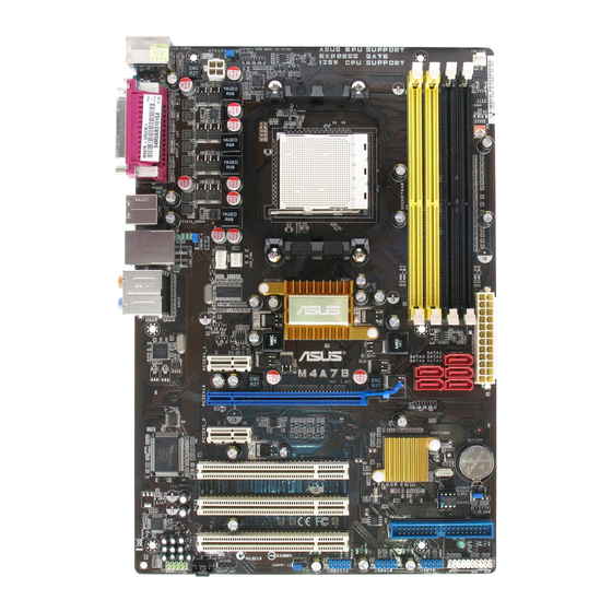
Page 17: Motherboard Layout
1.5.3 Motherboard layout 1.5.4 Layout contents Connectors/Jumpers/Slots Page Connectors/Jumpers/Slots Page USB device wake-up (3-pin USBPW1-6 and 1-20 IDE connector (40-1 pin PRI_EIDE) 1-24 USBPW7-12) ATX power connectors 1-23 10. Onboard LED (24-pin EATXPWR, 4-pin ATX12V) Keyboard/mouse power (3-pin KBPWR) 1-20 11. -
Page 18: Central Processing Unit (Cpu)
Press the lever sideways to unlock the socket, then lift it up to a 90°- Socket lever 100° angle. Ensure that the socket lever is lifted up to 90°-100° angle, otherwise the CPU will not fit in completely. ASUS M4A78... - Page 19 Position the CPU above the socket such that the CPU corner with the gold triangle matches the socket corner with a small triangle. Carefully insert the CPU into the socket until it fits in place. The CPU fits only in one correct orientation.
-
Page 20: Installing The Heatsink And Fan
Your boxed CPU heatsink and fan assembly should come with installation instructions for the CPU, heatsink, and the retention mechanism. If the instructions in this section do not match the CPU documentation, follow the latter. Attach one end of the retention bracket to the retention module base. 1-10 ASUS M4A78... -
Page 21: System Memory
Align the other end of the retention bracket to the retention module base. A clicking sound denotes that the retention bracket is in place. Ensure that the fan and heatsink assembly perfectly fits the retention mechanism module base, otherwise you cannot snap the retention bracket in place. Push down the retention bracket lock on the retention mechanism to secure the heatsink and fan to the module base. -
Page 22: Memory Configurations
The motherboard supports up to 16GB memory modules on Windows XP Professional x64 ® and Vista x64 editions. You may install a maximum of 4GB DIMMs on each slot. M4A78 Motherboard Qualified Vendors Lists (QVL) DDR2-533MHz capability DIMM support Chip... - Page 23 DDR2-667MHz capability DIMM support Chip Size Vendor Part No. Chip No. Brand Kingston KVR667D2N5/2G 7RE22 D9HNL Micron · · · 512MB Kingston KVR667D2N5/512 SO1237650821 SBP Kingston · · · D6408TR4CGL25USL0749 05PECNB Kingston KVR667D2N5/2G E1108ACBG-8E-E Elpida · · · 0813A90CC Kingston KVR667D2N5/1G SO1280420822 SOP Kingston...
- Page 24 · · · Transcend JM800QLU-2G TQ243PCF8 Transcend · · · Transcend TS256MLQ64V8U E1108ACBG-8E-E Elpida · · · ADATA M2OAD6G314170Q1E58 AD29608A8A-25EG80810 ADATA · · · 512MB VDATA M2GVD6G3H3160Q1E52 VD29608A8A-25EG20813 VDATA · · · (continued on the next page) 1-14 ASUS M4A78...
- Page 25 DIMM support Chip Size Vendor Part No. Chip No. Brand AL8E8F73C-8E1 A3R1GE3CFF734MAA0E · · · PL8E8F73C-8E1 SHG772-AA3G · · · PL8E8G73E-8E1 XCP271A3G-A · · · AL7E8E63H-10E1K A3R1GE3CFF750RABBP(ECC) · · · GEIL GB22GB6400C4DC GL2L64M088BA30EB GEIL · · · GEIL GB24GB6400C4QC GL2L64M088BA30EB GEIL ·...
- Page 26 • B*: Supports one pair of modules inserted into both the yellow slots as one pair of Dual-channel memory configuration. • C*: Supports four modules inserted into both the yellow slots and the black slots as two pairs of Dual-channel memory configuration. Visit the ASUS website at www.asus.com for the latest QVL. 1-16 ASUS M4A78...
-
Page 27: Installing A Dimm
1.7.3 Installing a DIMM Unplug the power supply before adding or removing DIMMs or other system components. Failure to do so can cause severe damage to both the motherboard and the components. Press the retaining clips outward to DDR2 DIMM notch unlock a DDR2 DIMM socket. -
Page 28: Expansion Slots
This motherboard supports PCI Express x1 network cards, SCSI cards, and other cards that comply with the PCI Express specifications. 1.8.5 PCI Express x16 slot This motherboard supports a PCI Express x16 graphics card that complies with the PCI Express specifications. 1-18 ASUS M4A78... -
Page 29: Jumpers
Jumpers Clear RTC RAM (CLRTC) This jumper allows you to clear the Real Time Clock (RTC) RAM in CMOS. You can clear the CMOS memory of date, time, and system setup parameters by erasing the CMOS RTC RAM data. The onboard button cell battery powers the RAM data in CMOS, which include system setup information such as system passwords. -
Page 30: Usb Device Wake-Up
Set to +5VSB to wake up from S3 and S4 sleep modes (no power to CPU, DRAM in slow refresh, power supply in reduced power mode). This jumper is for the internal USB connectors that you can connect to additional USB ports. 1-20 ASUS M4A78... -
Page 31: Connectors
1.10 Connectors 1.10.1 Rear panel connectors 5 6 7 8 PS/2 Keyboard/Mouse Combo port (purple). This port is for a PS/2 keyboard or mouse. Parallel port. This 25-pin port connects a parallel printer, a scanner, or other devices. USB 2.0 ports 3 and 4. These two 4-pin Universal Serial Bus (USB) ports are available for connecting USB 2.0 devices. - Page 32 DO NOT insert different connectors to the external SATA port. Serial port. This 9-pin COM1 port is for pointing devices or other serial devices. USB 2.0 ports 5 and 6. These two 4-pin Universal Serial Bus (USB) ports are available for connecting USB 2.0 devices. 1-22 ASUS M4A78...
-
Page 33: Internal Connectors
The system may become unstable or may not boot up if the power is inadequate. • If you are uncertain about the minimum power supply requirement for your system, refer to the Recommended Power Supply Wattage Calculator at http://support.asus. com/PowerSupplyCalculator/PSCalculator.aspx?SLanguage=en-us for details. Chapter 1: Product introduction... -
Page 34: Ide Connector (40-1 Pin Pri_Eide)
This prevents incorrect insertion when you connect the IDE cable. • Use the 80-conductor IDE cable for Ultra DMA 133/100 IDE devices. If any device jumper is set as “Cable-Select”, ensure that all other device jumpers have the same setting. 1-24 ASUS M4A78... - Page 35 Serial ATA connectors (7-pin SATA1, SATA2, SATA3, SATA5, SATA6) These connectors are for the Serial ATA signal cables for Serial ATA 3Gb/s hard disk and optical disk drives. The Serial ATA 3Gb/s is backward compatible with Serial ATA 1.5Gb/s specification. The data transfer rate of the Serial ATA 3Gb/s is faster than the standard parallel ATA with 133 MB/s (Ultra DMA133).
-
Page 36: System Panel Connector (20-8 Pin F_Panel)
Pressing the power switch for more than four seconds while the system is ON turns the system OFF. • Reset button (2-pin RESET) This 2-pin connector is for the chassis-mounted reset button for system reboot without turning off the system power. 1-26 ASUS M4A78... -
Page 37: Usb Connectors (10-1 Pin Usb78, Usb910, Usb1112)
USB connectors (10-1 pin USB78, USB910, USB1112) These connectors are for USB 2.0 ports. Connect the USB module cable to any of these connectors, then install the module to a slot opening at the back of the system chassis. These USB connectors comply with USB 2.0 specification that supports up to 480 Mbps connection speed. -
Page 38: Digital Audio Connector (4-1 Pin Spdif_Out)
Ensure that the audio device of Sound playback is Realtek High Definition Audio (the name may be different based on the OS). Go to Start > Control Panel > Sounds and Audio Devices > Sound Playback to configure the setting. The S/PDIF module is purchased separately. 1-28 ASUS M4A78... -
Page 39: Front Panel Audio Connector (10-1 Pin Aafp)
Do not forget to connect the fan cables to the fan connectors. Insufficient air flow inside the system may damage the motherboard components. These are not jumpers! Do not place jumper caps on the fan connectors! Only the CPU fan supports the ASUS Q-FAN feature. Chapter 1: Product introduction 1-29... -
Page 40: Software Support
The contents of the Support DVD are subject to change at any time without notice. Visit the ASUS website at www.asus.com for updates. To run the Support DVD Place the Support DVD to the optical drive. -
Page 41: Chapter 2 Bios Setup
BIOS in the future. Copy the original motherboard BIOS using the ASUS Update or AFUDOS utilities. 2.1.1 ASUS Update utility The ASUS Update is a utility that allows you to manage, save, and update the motherboard BIOS in Windows environment. ®... -
Page 42: Asus Ez Flash 2 Utility
2.1.2 ASUS EZ Flash 2 utility The ASUS EZ Flash 2 feature allows you to update the BIOS without having to use an OS-based utility. Before using this utility, download the latest BIOS file from the ASUS website at www.asus. -
Page 43: Asus Crashfree Bios 3 Utility
2.1.3 ASUS CrashFree BIOS 3 utility The ASUS CrashFree BIOS 3 is an auto recovery tool that allows you to restore the BIOS file when it fails or gets corrupted during the updating process. You can update a corrupted BIOS file using the motherboard support DVD or a USB flash disk that contains the updated BIOS file. -
Page 44: Bios Setup Program
• The BIOS setup screens shown in this section are for reference purposes only, and may not exactly match what you see on your screen. • Visit the ASUS website at www.asus.com to download the latest BIOS file for this motherboard. -
Page 45: Bios Menu Screen
• The BIOS setup screens shown in this chapter are for reference purposes only, and may not exactly match what you see on your screen. • Visit the ASUS website at www.asus.com to download the latest BIOS information. Chapter 2: BIOS setup... -
Page 46: Navigation Keys
(C)Copyright 1985-2008, A m e r i c a n Megatrends, Inc. Pop-up window Press the Scroll bar <Up> / <Down> arrow keys or <Page Up> /<Page Down> keys to display the other items on the screen. ASUS M4A78... -
Page 47: Main Menu
Main menu When you enter the BIOS Setup program, the Main menu screen appears, giving you an overview of the basic system information. Refer to section “2.2.1 BIOS menu screen” for information on the menu screen items and how to navigate through them. BIOS SETUP UTILITY Main Advanced... -
Page 48: Sata 1, Sata 2, Sata 3, Sata 5, Sata 6, And Esata
DMA Mode [Auto] Selects the DMA mode. Configuration options: [Auto] SMART Monitoring [Auto] Sets the Smart Monitoring, Analysis, and Reporting Technology. Configuration options: [Auto] [Disabled] [Enabled] 32Bit Data Transfer [Enabled] Enables or disables 32-bit data transfer. Configuration options: [Disabled] [Enabled] ASUS M4A78... -
Page 49: Sata Configuration
2.3.5 SATA Configuration This menu allows you to configure the SATA devices. OnChip SATA Channel [Enabled] Enables or disables the OnChip SATA Channel. Configuration options: [Enabled] [Disabled] OnChip SATA Type [SATA] Allows you to select the SATA type. Configuration options: [SATA] [RAID] [AHCI] When SATA is configured as [AHCI] in BIOS, only SATA port 1-3 can be detected. -
Page 50: Jumperfree Configuration
Configuration options: [200 Mhz] [400 Mhz] [600 Mhz] [800 Mhz] [1 Ghz] [Auto] Hyper Transport Width [Auto] The Hyper Transport link will run at this width. Configuration options: [Auto] [8 Bit] [16 Bit] 2-10 ASUS M4A78... - Page 51 Memory Clock Mode [Auto] Allows you to set the memory clock mode. Configuration options: [Auto] [Manual] The following item appears only when the Memory clock mode item is set to [Manual]. Memclock Value [200 MHz] Allows you to set the Memclock value. Configuration options: [200 MHz] [266 MHz] [333 MHz] [400 MHz] DRAM Timing Mode [Auto] Allows you to set the DRAM timing mode.
-
Page 52: Cpu Configuration
Configuration options: [Disabled] [Enabled] CPU Prefetching [Enabled] Allows you to enable or disable the CPU prefetching. Configuration options: [Enabled] [Disabled] C1E Configuration [Disabled] Allows you to enable or disable C1E Dual-Core related CPU power State. Configuration options: [Disabled] [Auto] 2-12 ASUS M4A78... -
Page 53: Chipset
2.4.3 Chipset The Chipset menu allows you to change the advanced chipset settings. Select an item then press <Enter> to display the submenu. NorthBridge Configuration Memory Configuration Bank Interleaving [Auto] Allows you to enable the bank memory interleaving. Configuration options: [Disabled] [Auto] Channel Interleaving [Disabled] Allows you to enable the channel memory interleaving. -
Page 54: Onboard Devices Configuration
When set to [No], BIOS configures all the devices in the system. When set to [Yes] and if you install a Plug and Play operating system, the operating system configures the Plug and Play devices not required for boot. Configuration options: [No] [Yes] 2-14 ASUS M4A78... -
Page 55: Usb Configuration
2.4.6 USB Configuration The items in this menu allows you to change the USB-related features. Select an item then press <Enter> to display the configuration options. The Module Version and USB Devices Enabled items show the auto-detected values. If no USB device is detected, the item shows None. -
Page 56: Power Menu
When set to Power Off, the system goes into off state after an AC power loss. When set to Power On, the system goes on after an AC power loss. Configuration options: [Power On] [Power Off] [Last State] 2-16 ASUS M4A78... -
Page 57: Hw Monitor Configuration
N/A. Select Ignored if you do not wish to display the detected speed. Smart Q-Fan Function [Disabled] Allows you to enable or disable the ASUS Q-Fan feature that smartly adjusts the fan speeds for more efficient system operation. Configuration options: [Disabled] [Enabled] CPU Fan Profile [Optimal] Allows you to select the CPU fan profile. -
Page 58: Boot Menu
This allows you to enable or disable the full screen logo display feature. Configuration options: [Disabled] [Enabled] Set this item to [Enabled] to use the ASUS MyLogo 2™ feature. AddOn ROM Display Mode [Force BIOS] Sets the display mode for option ROM. Configuration options: [Force BIOS] [Keep Current]... -
Page 59: Security
Bootup Num-Lock [On] Allows you to select the power-on state for the NumLock. Configuration options: [Off] [On] Wait for ‘F1’ If Error [Enabled] When set to Enabled, the system waits for the F1 key to be pressed when error occurs. Configuration options: [Disabled] [Enabled] Hit ‘DEL’... -
Page 60: Tools Menu
(C)Copyright 1985-2007, American Megatrends, Inc. 2.7.1 ASUS EZ Flash 2 Allows you to run ASUS EZ Flash 2. When you press <OK>, a confirmation message appears. Use the left/right arrow key to select between [Yes] or [No], then press <OK> to confirm your choice. -
Page 61: Express Gate
2.7.2 Express Gate [Enabled] Allows you to enable or disable the ASUS Express Gate feature. The ASUS Express Gate feature is a unique instant-on environment that provides quick access to the Internet browser and Skype. Configuration options: [Enabled] [Disabled] Enter OS Timer [10 Seconds] Sets countdown duration that the system waits at the Express Gate’s first screen... -
Page 62: Exit Menu
When you select this option or if you press <F5>, a confirmation window appears. Select OK to load default values. Select Exit & Save Changes or make other changes before saving the values to the non-volatile RAM. 2-22 ASUS M4A78...