Table of Contents
Advertisement
Advertisement
Table of Contents

Related Manuals for Asus M4A77T/USB3


Summary of Contents for Asus M4A77T/USB3
- Page 1 M4A77T/USB3...
- Page 2 Product warranty or service will not be extended if: (1) the product is repaired, modified or altered, unless such repair, modification of alteration is authorized in writing by ASUS; or (2) the serial number of the product is defaced or missing.
-
Page 3: Table Of Contents
Contents Notices ......................vi Safety information ..................vii About this guide ..................vii M4A77T/USB3 specifications summary ........... ix Chapter 1: Product introduction Welcome! ..................1-1 Package contents ................. 1-1 Special features ................1-1 1.3.1 Product highlights ............1-1 1.3.2 Innovative ASUS features ..........1-3 Before you proceed .............. - Page 4 Chapter 2: BIOS information Managing and updating your BIOS ..........2-1 2.1.1 ASUS Update utility ............2-1 2.1.2 ASUS EZ Flash 2 ............2-2 2.1.3 ASUS CrashFree BIOS ........... 2-3 BIOS setup program ..............2-4 2.2.1 BIOS menu screen ............2-5 2.2.2...
- Page 5 Boot Device Priority ............2-18 2.6.2 Boot Settings Configuration .......... 2-18 2.6.3 Security ................. 2-19 Tools menu ................. 2-20 2.7.1 ASUS EZ Flash 2 ............2-20 2.7.2 Express Gate ..............2-21 2.7.3 ASUS O.C. Profile ............2-21 2.7.4 AI NET 2................ 2-22...
-
Page 6: Notices
Complying with the REACH (Registration, Evaluation, Authorisation, and Restriction of Chemicals) regulatory framework, we published the chemical substances in our products at ASUS REACH website at http://green.asus.com/english/REACH.htm. DO NOT throw the motherboard in municipal waste. This product has been designed to enable proper reuse of parts and recycling. -
Page 7: Safety Information
Safety information Electrical safety • To prevent electric shock hazard, disconnect the power cable from the electric outlet before relocating the system. • When adding or removing devices to or from the system, ensure that the power cables for the devices are unplugged before the signal cables are connected. If possible, disconnect all power cables from the existing system before you add a device. -
Page 8: Conventions Used In This Guide
Refer to the following sources for additional information and for product and software updates. ASUS websites The ASUS website provides updated information on ASUS hardware and software products. Refer to the ASUS contact information. Optional documentation Your product package may include optional documentation, such as warranty flyers, that may have been added by your dealer. -
Page 9: M4A77T/Usb3 Specifications Summary
100 and 200 series CPUs support up to ® DDR3 1066MHz. With ASUS design, this motherboard can support up to DDR3 1333MHz. ** Refer to www.asus.com for the latest Memory QVL (Qualified Vendors List). *** When you install a total memory of 4GB or more, Windows ®... - Page 10 M4A77T/USB3 specifications summary ASUS unique features Protect 3.0 Core Unlocker MemOK! 100% All High-quality Conductive Polymer Capacitors ASUS Anti-Surge Protection ASUS Turbo Key ASUS Express Gate ASUS EPU-4 Engine ASUS O.C. Profile ASUS CrashFree BIOS 3 ASUS AI NET 2...
-
Page 11: Chapter 1: Product Introduction
® The motherboard delivers a host of new features and latest technologies, making it another standout in the long line of ASUS quality motherboards! Before you start installing the motherboard, and hardware devices on it, check the items in your package with the list below. - Page 12 770 Chipset ® The AMD 770 Chipset is designed to support up to 5200MT/s ® HyperTransport™ 3.0 (HT 3.0) interface speed and PCI Express 2.0 x16 graphics. It is optimized with AMD’s latest AM3 multi-core CPUs to provide excellent system performance and overclocking capabilities. AMD Cool ‘n’...
-
Page 13: Innovative Asus Features
Internet without entering the Windows ® • ASUS Express Gate supports installation on SATA HDDs, USB HDDs and flash drives with at least 1.2GB free disk space. When installing it on USB HDDs or flash drives, connect the drives to the motherboard USB port before turning on the computer. -
Page 14: Before You Proceed
ASUS EZ Flash 2 ASUS EZ Flash 2 allows you to update the BIOS from a USB flash disk before entering the OS. ASUS MyLogo 2™ Turn your favorite photos into 256-color boot logos to personalize your system. ASUS Q-Fan ASUS Q-Fan technology intelligently adjusts CPU fan speeds according to system loading to ensure a quiet, cool, and efficient operation. -
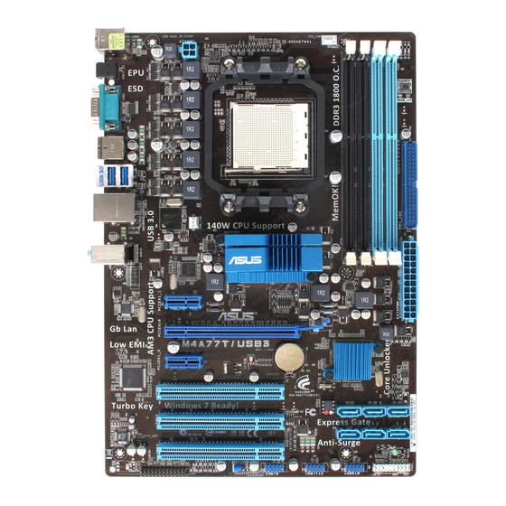
Page 15: Motherboard Overview
Screw holes Place six screws into the holes indicated by circles to secure the motherboard to the chassis. DO NOT overtighten the screws! Doing so can damage the motherboard. Place this side towards the rear of the chassis. M4A77T/USB3 ASUS M4A77T/USB3... -
Page 16: Motherboard Layout
21.3cm(8.4in) CPU_FAN KBMS ATX12V MemOK! DRAM_LED PRI_IDE USB34 USB_3.0_12 LAN1_USB12 CHA_FAN AUDIO ® 9LPRS477 AAFP PCIEX1_1 Realtek RTL8112L PCIEX16 M4A77T/USB3 ® Lithium Cell CMOS Power PCIEX1_2 SB710 Super PCI1 SATA1 SATA2 SATA3 BIOS PCI2 SATA4 SATA5 SATA6 SPDIF_OUT VT1708S SB_PWR... -
Page 17: Central Processing Unit (Cpu)
Installing the CPU To install a CPU: Locate the CPU socket on the motherboard. M4A77T/USB3 M4A77T/USB3 CPU socket AM3 Press the lever sideways to unlock the Socket lever socket, then lift it up to a 90°-100° angle. Ensure that the socket lever is lifted up to a 90°-100° angle; otherwise, the CPU will not fit in completely. - Page 18 Connect the CPU fan cable to the CPU_FAN connector on the motherboard. CPU_FAN M4A77T/USB3 M4A77T/USB3 CPU fan connector DO NOT forget to connect the CPU fan connector! Hardware monitoring errors can occur if you fail to plug this connector. Chapter 1: Product introduction...
-
Page 19: Installing The Heatsink And Fan
Your boxed CPU heatsink and fan assembly should come with installation instructions for the CPU, heatsink, and the retention mechanism. If the instructions in this section do not match the CPU documentation, follow the latter. Attach one end of the retention bracket to the retention module base. ASUS M4A77T/USB3... -
Page 20: System Memory
The figure illustrates the location of the DDR3 DIMM sockets: Channel Sockets Channel A DIMM_A1 and DIMM_A2 Channel B DIMM_B1 and DIMM_B2 M4A77T/USB3 M4A77T/USB3 240-pin DDR3 DIMM sockets 1-10 Chapter 1: Product introduction... -
Page 21: Memory Configurations (Am3, 2-Channel)
• Due to CPU spec., AMD 100 and 200 series CPUs support up to DDR3 1066MHz. With ® ASUS design, this motherboard can support up to DDR3 1333MHz. • When overclocking, some AMD CPUs may not support DDR3 1600MHz or higher frequency DIMMs. - Page 22 DDR3-1600(O.C.)MHz capability DIMM support Chip Vendor Part No. Size Chip NO. Brand A-Data AD31600X002GMU 4096MB(Kit of 2) Heat-Sink Package 7-7-7-20 • Corsair CM3X1G1600C9DHX 2048MB(Kit of 2) Heat-Sink Package 9-9-9-24 • • • CRUCIAL BL12864BA1608.8SFB(XMP) 3072MB(Kit of 3) Heat-Sink Package 8-8-8-24 •...
- Page 23 2048MB Heat-Sink Package • PATRIOT PSD31G13332H 1024MB Heat-Sink Package • • • Patriot PSD31G13332 1024MB Patriot PM64M8D38U-15 • • Takems TMS1GB364D081-107EY 1024MB Heat-Sink Package 7-7-7-20 • • • Takems TMS1GB364D081-138EY 1024MB Heat-Sink Package 8-8-8-24 • • • ASUS M4A77T/USB3 1-13...
- Page 24 • Due to CPU spec., AMD 100 and 200 series CPUs support up to DDR3 1066MHz. With ® ASUS design, this motherboard can support up to DDR3 1333MHz. • When overclocking, some AMD CPU models may not support DDR3 1600 MHz or higher frequency DIMMs.
-
Page 25: Installing A Dimm
DIMM. Support the DIMM lightly with your fingers when pressing the retaining clips. The DIMM might get damaged when it flips out with extra force. DIMM notch Remove the DIMM from the socket. ASUS M4A77T/USB3 1-15... -
Page 26: Expansion Slots
Expansion slots In the future, you may need to install expansion cards. The following sub-sections describe the slots and the expansion cards that they support. Unplug the power cord before adding or removing expansion cards. Failure to do so may cause you physical injury and damage motherboard components. -
Page 27: Jumpers
Normal Clear RTC (Default) M4A77T/USB3 Clear RTC RAM To erase the RTC RAM: 1. Turn OFF the computer and unplug the power cord. 2. Move the jumper cap from pins 1-2 (default) to pins 2-3. Keep the cap on pins 2-3 for about 5~10 seconds, then move the cap back to pins 1-2. -
Page 28: Connectors
1.10 Connectors 1.10.1 Rear panel ports PS/2 Mouse port (green). This port is for a PS/2 mouse. LAN (RJ-45) port. This port allows Gigabit connection to a Local Area Network (LAN) through a network hub. LAN port LED indications ACT/LINK SPEED Activity/Link LED Speed LED... -
Page 29: Internal Connectors
DO NOT forget to connect the fan cables to the fan connectors. Insufficient air flow inside the system may damage the motherboard components. These are not jumpers! DO NOT place jumper caps on the fan connectors. Only the 4-pin CPU fan supports the ASUS Q-Fan feature. ASUS M4A77T/USB3 1-19... -
Page 30: Atx Power Connectors
The system may become unstable or may not boot up if the power is inadequate. • If you are uncertain about the minimum power supply requirement for your system, refer to the Recommended Power Supply Wattage Calculator at http://support.asus. com/PowerSupplyCalculator/PSCalculator.aspx?SLanguage=en-us for details. 1-20... - Page 31 • Use the 80-conductor IDE cable for Ultra DMA 133/100/66 IDE devices. If any device jumper is set as “Cable-Select”, ensure that all other device jumpers have the same setting. PRI_IDE M4A77T/USB3 PIN1 NOTE:Orient the red markings on the IDE ribbon cable to PIN 1. M4A77T/USB3 IDE connector ASUS M4A77T/USB3 1-21...
- Page 32 SATA4 SATA5 SATA6 M4A77T/USB3 M4A77T/USB3 SATA connectors • Install the Windows XP Service Pack 2 or later versions before using Serial ATA. ® • If you intend to create a Serial ATA RAID set using these connectors, set the type of the SATA connectors in the BIOS to [RAID].
- Page 33 IDE_LED PWRSW RESET * Requires an ATX power supply M4A77T/USB3 System panel connector • System power LED (2-pin PLED) This 2-pin connector is for the system power LED. Connect the chassis power LED cable to this connector. The system power LED lights up when you turn on the system power, and blinks when the system is in sleep mode.
-
Page 34: Digital Audio Connector
Legacy AC’97 pin definition compliant definition M4A77T/USB3 Front panel audio connector • We recommend that you connect a high-definition front panel audio module to this connector to avail of the motherboard high-definition audio capability. • If you want to connect a high definition front panel audio module to this connector, set the Front Panel Select item in the BIOS to [HD Audio]. - Page 35 USB910 M4A77T/USB3 PIN 1 PIN 1 PIN 1 M4A77T/USB3 USB2.0 connectors Never connect a 1394 cable to the USB connectors. Doing so will damage the motherboard! The USB 2.0 module is purchased separately. LPT connector (26-1 pin LPT) The LPT (Line Printing Terminal) connector supports devices such as a printer. LPT is standardized as IEEE 1284, which is the parallel port interface on IBM PC-compatible computers.
-
Page 36: Memok! Switch
If the installed DIMMs still fail to boot after the whole tuning process, the DRAM_LED lights continuously. Replace the DIMMs with ones recommended in the Memory QVL (Qualified Vendors Lists) in this user manual or on the ASUS website at www.asus.com. -
Page 37: Onboard Leds
M4A77T/USB3 Standby Power Powered Off M4A77T/USB3 Onboard LED DRAM LED DRAM LED checks the DRAM in sequence during motherboard booting process. If an error is found , the LED next to the error device will continue lighting until the problem is solved. -
Page 38: Software Support
Place the Support DVD to the optical drive. If Autorun is enabled in your computer, the DVD automatically displays the Specials screen which contains the unique feature of ASUS motherboard. Click Drivers, Utilities, Make Disk, Manual, and Contact tabs to display their respective menus. -
Page 39: Managing And Updating Your Bios
BIOS in the future. Copy the original motherboard BIOS using the ASUS Update utility. 2.1.1 ASUS Update utility The ASUS Update is a utility that allows you to manage, save, and update the motherboard BIOS in Windows environment. ®... -
Page 40: Asus Ez Flash 2
Follow the onscreen instructions to complete the updating process. 2.1.2 ASUS EZ Flash 2 The ASUS EZ Flash 2 feature allows you to update the BIOS without using an OS-based utility. Before you start using this utility, download the latest BIOS file from the ASUS website at www.asus.com. -
Page 41: Asus Crashfree Bios
2.1.3 ASUS CrashFree BIOS The ASUS CrashFree BIOS is an auto recovery tool that allows you to restore the BIOS file when it fails or gets corrupted during the updating process. You can restore a corrupted BIOS file using the motherboard support DVD or a removable device that contains the updated BIOS file. -
Page 42: Bios Setup Program
• The BIOS setup screens in this chapter are for reference only. They may not exactly match what you see on your screen. • Visit the ASUS website at www.asus.com to download the latest BIOS file for this motherboard. Chapter 2: BIOS information... -
Page 43: Bios Menu Screen
At the bottom right corner of a menu screen are the navigation keys for that particular menu. Use the navigation keys to select items in the menu and change the settings. Some of the navigation keys differ from one screen to another. ASUS M4A77T/USB3... -
Page 44: Menu Items
2.2.4 Menu items The highlighted item on the menu bar displays the specific items for that menu. For example, selecting Main shows the Main menu items. The other items (Advanced, Power, Boot, Tools, and Exit) on the menu bar have their respective menu items. -
Page 45: Main Menu
CD-ROM drive. Select [ARMD] (ATAPI Removable Media Device) if your device is either a ZIP, LS-120, or MO drive. Configuration options: [Not Installed] [Auto] [CDROM] [ARMD] This item only appears in the Primary IDE Master/Slave and SATA5/6 menus. ASUS M4A77T/USB3... -
Page 46: Sata Configuration
LBA/Large Mode [Auto] Enables or disables the LBA mode. Setting this item to [Auto] enables the LBA mode if the device supports this mode, and if the device was not previously formatted with LBA mode disabled. Configuration options: [Disabled] [Auto] Block (Multi-Sector Transfer) M [Auto] Enables or disables data multi-sectors transfers. -
Page 47: System Information
The items and configuration options in this menu may vary depending on the AMD CPU type. CPU Level Up [Auto] Selects the desired CPU level, and other relevant parameters will be adjusted automatically based on the selected CPU level. Configuration options: [Auto] [Phenom II-955] [Phenom II-3.4G] [Phenom II-3.6G] ASUS M4A77T/USB3... - Page 48 Ai Overclock Tuner [Auto] Selects the CPU overclocking options to achieve desired CPU internal frequency. Configuration options: [Manual] [Auto] [Overclock Profile] [CPU Level Up] [Test Mode] The following items only appear when you set Ai Overclock Tuner to [Manual]. OC From CPU Level Up [Auto] Selects the desired CPU level, and other relevant parameters will be adjusted automatically based on the selected CPU level.
- Page 49 Configuration options: [Auto] [5 CLK] ~ [12 CLK] TRAS [Auto] Configuration options: [Auto] [15 CLK] ~ [30 CLK] TRTP [Auto] Configuration options: [Auto] [4 CLK] ~ [7 CLK] TRC [Auto] Configuration options: [Auto] [11 CLK] ~ [41 CLK] ASUS M4A77T/USB3 2-11...
- Page 50 TWR [Auto] Configuration options: [Auto] [5 CLK] [6 CLK] [7 CLK] [8 CLK] [10 CLK] [12 CLK] TRRD [Auto] Configuration options: [Auto] [4 CLK] ~ [7 CLK] TRWTTO [Auto] Configuration options: [Auto] [3 CLK] ~ [17 CLK] TWRRD [Auto] Configuration options: [Auto] [2 CLK] ~ [10 CLK] TWTR [Auto] Configuration options: [Auto] [4 CLK] ~ [7 CLK] TWRWR [Auto]...
-
Page 51: Cpu Configuration
Allows you to enable the bank memory interleaving. Configuration options: [Disabled] [Auto] Channel Interleaving [Auto] Allows you to enable the channel memory interleaving. Configuration options: [Disabled] [Address bits 6] [Address bits 12] [Auto] [XOR of Address bits [20:16, 6]] [XOR of Address bits [20:16, 9]] ASUS M4A77T/USB3 2-13... -
Page 52: Onboard Devices Configuration
MemClk Tristate C3/ATLVID [Disabled] Allows you to enable or disable MemClk Tri-Stating during C3 and Alt VID. Configuration options: [Disabled] [Enabled] Memory Hole Remapping [Enabled] Allows you to enable or disable memory remapping around memory hole. Configuration options: [Disabled] [Enabled] DCT Unganged Mode [Always] Allows you to select the unganged DRAM mode (64-bit width). -
Page 53: Pcipnp
Sets the maximum time that the BIOS waits for the USB storage device to initialize. Configuration options: [10 Sec] [20 Sec] [30 Sec] [40 Sec] Emulation Type [Auto] Allows you to set the emulation type. Configuration options: [Auto] [Floppy] [Forced FDD] [Hard Disk] [CDROM] ASUS M4A77T/USB3 2-15... -
Page 54: Power Menu
Power menu The Power menu items allow you to change the settings for the Advanced Configuration and Power Interface (ACPI) and the Advanced Power Management (APM). Select an item then press <Enter> to display the configuration options. BIOS SETUP UTILITY Main Advanced Power... -
Page 55: Hw Monitor Configuration
The onboard hardware monitor automatically detects the voltage output through the onboard voltage regulators. Select [Ignored] if you do not want the detected voltage to be displayed. 2.5.6 Anti Surge Support [Enabled] Allows you to enable or disable the Anti-Surge protection feature. Configuration options: [Disabled] [Enabled] ASUS M4A77T/USB3 2-17... -
Page 56: Boot Menu
Configuration options: [Removable Dev.] [Hard Drive] [ATAPI CD-ROM] [Disabled] • To select the boot device during system startup, press <F8> when ASUS Logo appears. • To access Windows OS in Safe Mode, do any of the following: ®... -
Page 57: Security
View Only allows access but does not allow change to any field. Limited allows changes only to selected fields, such as Date and Time. Full Access allows viewing and changing all the fields in the Setup utility. ASUS M4A77T/USB3 2-19... -
Page 58: Tools Menu
(C)Copyright 1985-2009, American Megatrends, Inc. 2.7.1 ASUS EZ Flash 2 Allows you to run ASUS EZ Flash 2. When you press <Enter>, a confirmation message appears. Use the left/right arrow key to select between [Yes] or [No], then press <Enter> to confirm your choice. -
Page 59: Express Gate
2.7.2 Express Gate [Auto] Enables or disables the ASUS Express Gate feature. ASUS Express Gate is a unique instant-on environment that provides quick access to the Internet and Skype. Configuration options: [Disabled] [Enabled] [Auto] Enter OS Timer [10 Seconds] Sets countdown duration that the system waits at the Express Gate’s first screen before starting Windows or other installed OS. -
Page 60: Ai Net 2
2.7.4 AI NET 2 Check Realtek LAN cable [Disabled] Enables or disables checking of the Realtek LAN cable during the Power-On Self-Test (POST). Configuration options: [Disabled] [Enabled] Exit menu The Exit menu items allow you to load the optimal or failsafe default values for the BIOS items, and save or discard your changes to the BIOS items. -
Page 61: Asus Contact Information
+1-510-739-3777 +1-510-608-4555 Web site usa.asus.com Technical Support Telephone +1-812-282-2787 Support fax +1-812-284-0883 Online support support.asus.com ASUS COMPUTER GmbH (Germany and Austria) Address Harkort Str. 21-23, D-40880 Ratingen, Germany +49-2102-959911 Web site www.asus.de Online contact www.asus.de/sales Technical Support Telephone (Component) +49-1805-010923*...