Table of Contents
Advertisement
Quick Links
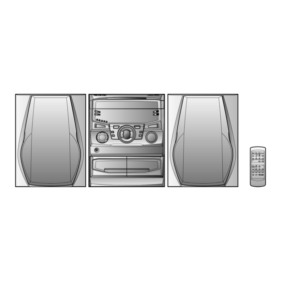
Illustration: CD-C661H
SAFETY PRECAUTION FOR SERVICE MANUAL ........................................................................................................... 2
IMPORTANT SERVICE NOTES (CD-C661H FOR U.K. ONLY) ....................................................................................... 2
SPECIFICATIONS .............................................................................................................................................................. 3
NAMES OF PARTS ........................................................................................................................................................... 4
OPERATION MANUAL ...................................................................................................................................................... 6
DISASSEMBLY .................................................................................................................................................................. 7
REMOVING AND REINSTALLING THE MAIN PARTS ..................................................................................................... 9
ADJUSTMENT ................................................................................................................................................................. 10
NOTES ON SCHEMATIC DIAGRAM .............................................................................................................................. 16
BLOCK DIAGRAM ........................................................................................................................................................... 17
SCHEMATIC DIAGRAM / WIRING SIDE OF P.W.BOARD .............................................................................................. 20
VOLTAGE ........................................................................................................................................................................ 38
WAVEFORMS OF CD CIRCUIT ...................................................................................................................................... 39
TROUBLESHOOTING (CD SECTION) ........................................................................................................................... 40
FUNCTION TABLE OF IC ................................................................................................................................................ 45
WIRING OF PRIMARILY SUPPLY LEADS (CD-C661H FOR U.K. ONLY) ..................................................................... 51
FL DISPLAY ...................................................................................................................................................................... 52
PARTS GUIDE/EXPLODED VIEW
DIFFERENCE BETWEEN CD-C661H AND CD-C661HR
SERVICE MANUAL
CONTENTS
CD-C661H
Speaker
SHARP CORPORATION
- 1 -
CD-C661H
CD-C661HR
CD-C661H mini component system consisting of CD-C661H
(main unit) and CP-C661H (speaker system).
• In the interests of user-safety the set should be restored to its
original condition and only parts identical to those specified be
used.
• Note for users in U.K.
Recording and playback of any material may require consent
which SHARP is unable to give. Please refer particularly to the
provisions of Copyright Act 1956, the Dramatic and Musical
Prefomers Protection Act 1956, the Preformers Protection Acts
1963 and 1972 and to any subsequent statutory enactments and
orders.
CD-C661HR
This document has been published to be used
for after sales service only.
The contents are subject to change without notice.
CD-C661H/HR
No. S5926CDC661HR
Page
Advertisement
Table of Contents

Related Manuals for Sharp CD-C661H


Summary of Contents for Sharp CD-C661H
-
Page 1: Table Of Contents
WAVEFORMS OF CD CIRCUIT ............................39 TROUBLESHOOTING (CD SECTION) ........................... 40 FUNCTION TABLE OF IC ..............................45 WIRING OF PRIMARILY SUPPLY LEADS (CD-C661H FOR U.K. ONLY) ..............51 FL DISPLAY ..................................52 PARTS GUIDE/EXPLODED VIEW PACKING METHOD (CD-C661H FOR U.K. ONLY) -
Page 2: Safety Precaution For Service Manual
OSY NLI G KLASS 1 LASERAPPARAT LASERSTRèLNING, SOM ôVERSKRIDER GRéNSEN FôR LASERKLASS 1. IMPORTANT SERVICE NOTES (CD-C661H FOR U.K. ONLY) WITHSTANDING Before returning the unit to the customer after completion of a VOLTAGE TESTER repair or adjustment it is necessary for the following withstand... -
Page 3: Specifications
Height; 330 mm (13") playback) Depth; 358 mm (14-1/8") Wow and flutter: 0.2 % (DIN 45 511) Weight: 10.5 kg (23.1 lbs.) (CD-C661H Except for U.K./CD-C661HR) Wow and flutter: 0.15 % (WRMS) Amplifier section Output power: PMPO; 880 W (total) (CD-C661H For U.K.) -
Page 4: Names Of Parts
CD-C661H/HR NAMES OF PARTS CD-C661H/661HR Front Panel 1. Disc Number Selector Buttons 2. Disc Tray 3. Multi Indicator 4. Disc Skip Button 5. Open/Close Button 6. RDS Indicator 7. Programme Type Indicator 8. Traffic Information Indicator 6 7 8 9. Extra Bass Indicator 10. - Page 5 2. AC Power Lead 3. FM 75 Ohms Aerial Socket 4. AM Loop Aerial Input Socket 5. Video/Auxiliary (Audio Signal) Input Sockets 6. Speaker Terminals CP-C661H (CD-C661H ONLY) Speaker 1. Super Tweeter 2. Tweeter 3. Woofer 4. Bass Reflex Ducts 5.
-
Page 6: Operation Manual
CD-C661H/HR OPERATION MANUAL – 6 –... -
Page 7: Disassembly
CD-C661H/HR DISASSEMBLY CD-C661H/661HR Caution on Disassembly Follow the below-mentioned notes when disassembling Top Cabinet the unit and reassembling it, to keep it safe and ensure Front Panel excellent performance: (A1) x2 1. Take cassette tape and compact disc out of the unit. - Page 8 CD-C661H/HR (L1) x1 ø3 x10mm Front Panel (E2) x3 (D1) x1 ø3 x10mm (L2) x1 Washer (E3) x1 Turntable (F2) x1 Power Supply Main PWB Disc Tray (M1) x1 ø3 x10mm (E1) x1 Tuner ø3 x10mm (M2) x1 (F1) x3 ø3 x10mm...
-
Page 9: Removing And Reinstalling The Main Parts
CD-C661H/HR CP-C661H (CD-C661H ONLY) STEP REMOVAL PROCEDURE FIGURE Front Panel 1. Net ......(A1) x1 2. Rubber ....(A2) x4 3. Screw ..... (A3) x4 4. Tip ......(A4) x4 Woofer 1. Screw ..... (B1) x4 Tweeter 1. Screw ..... (C1) x4 Super Tweeter 1. -
Page 10: Adjustment
CD-C661H/HR ADJUSTMENT MECHANISM SECTION TUNER SECTION • Driving Force Check fL: Low-range frequency fH: High-renge frequency Torque Meter Specified Value • AM IF/RF Play: TW-2412 Tape 1: Over 80 g Signal generator: 400 Hz, 30%, AM modulated Tape 2: Over 80 g... - Page 11 CD-C661H/HR TEST MODE • Setting the test mode Any one of test mode can be set by pressing several keys as follows. <REC. PAUSE> + <DISC. SKIP> + <POWER> TEST: CD operation test • TEST mode Function — CD test mode Setting of TEST mode Indication of CD TST mode (Fig.
- Page 12 CD-C661H/HR – 12 –...
- Page 13 Preset memory takes priority of switching TN—ON station. Therefore ASPM is usefull not only for PTY search but also for rapid EON switching. Anyway CD-C661H/661HR EON is basically stand-by and receiving method, along with the Guidelines for EON implementation. – 13 –...
- Page 14 CD-C661H/HR EON summary notice for reference 1. EON-TI/PTY EON stand-by can be set, only when EON ind. lights up. While EON ind. goes out (NO EON STATION), EON stand-by can't be set. If the EON button is pressed, then “NO EON” is indication the display.
- Page 15 CD-C661H/HR – 15 –...
-
Page 16: Notes On Schematic Diagram
CD-C661H/HR NOTES ON SCHEMATIC DIAGRAM • The indicated voltage in each section is the one measured • Resistor: by Digital Multimeter between such a section and the chas- To differentiate the units of resistors, such symbol as K and sis with no signal given. -
Page 17: Block Diagram
CD-C661H/HR Figure 17 BLOCK DIAGRAM (1/3) – 17 –... - Page 18 CD-C661H/HR SO301 SWM3 ANTENNA FM IF AMP. FOOL PROOF TERMINAL FM IF FM IF FE301 SWM4 QT21 CF301 Q301 CF302 F.A.S AM IF FM FRONT END SOLM1 T351 FM IF IN SOLENOID SWM5 AM LOOP ANT FM/AM IC303 VR351 LA1832 FM MUTE LEVEL FM/AM IF MPX.
- Page 19 CD-C661H/HR SWM3 ROOF SWM4 F.A.S OLM1 NOID SWM5 FL701 DISPLAY Q702 1 2 3 4 37 38 39 Q703 TAPE MOTOR Q705 –B1 Q706 Q707 IC563 KIA4558P OPE AMP. IC562 KIA4558P OPE AMP. IC701 IX0281AW –B1 SYSTEM CONTROL MICROCOMPUTER IC704...
-
Page 20: Schematic Diagram / Wiring Side Of P.w.board
CD-C661H/HR MAIN PWB-A1 FM SIGNAL C601 CD SIGNAL C602 4.7/50 4.7/50 R601 1.5K R602 1.5K PLAYBACK SIGNAL R603 1.5K R604 1.5K RECORD SUGNAL R605 1.5K R606 1.5K R607 1.5K R608 1.5K C605 C606 4.7/50 4.7/50 C611 0.033 C612 0.033 C613 0.22 C614 0.22... - Page 21 CD-C661H/HR DIGITAL OUTPUT PWB-A4 D_OUT 1 P27 12 - D 100/10 0.022 +4.3V CNP99 TO CD SERVO PWB 2.2mmH CNS99 CD GND R639 JK601 R640 R651 R632 C632 R634 L-CH 8.2K 390P R641 VIDEO/AUX R633 R631 C631 R650 8.2K 390P...
- Page 22 CD-C661H/HR DISPLAY PWB-A2 FL701 1 2 3 4 5 6 7 8 9 10 11 12 13 14 15 16 17 18 19 20 21 22 23 24 25 26 27 28 29 30 31 3 FM SIGNAL R721 R722...
- Page 23 CD-C661H/HR P27 7 - G TO CD SERVO PWB CNP12 2 23 24 25 26 27 28 29 30 31 32 33 34 35 36 37 38 39 CNS12 1 2 3 4 5 6 7 8 9 1 2 3 4 5 6 7 8 9...
- Page 24 CD-C661H/HR IC901 – STK411-230E – FM SIGNAL POWER AMP. C913 R902 C911 R903 R905 Q903 D909 1SS133 KTC3199 GR C912 –B R917 0.1(3W) R909 R919 R906 C923 1.5K 0.022(ML) R915 3.9K R910 Q901 R921 C956 KTC3199 GR 4.7K 47/100 D907...
- Page 25 CD-C661H/HR POWER AMP.PWB-B2 R947 R945 (1/2W) (1/2W) C931 C935 0.022 0.022 (ML) SO901 (ML) C937 C933 RL901 SPEAKER L901 C939 0.022 0.022 TERMINAL 0.29µH 0.001 (ML) (ML) Q903 D909 L903 R925 KTC3199 GR L-CH 1SS133 10(1/2W) 0.29µH – C927 6 ohms –...
- Page 26 CD-C661H/HR 47/16 0.01 2SA1318 1/50 64 63 61 60 55 54 53 52 51 50 49 – FIN2 – FIN1 EFBAL – EREF – FOSTA – DGND TOSTA – 2FREQ CNP1 0.1/50 LASER – 0.033 TE– – LA9241M FSTA 100K SERVO AMP.
- Page 27 CD-C661H/HR R57 1K R58 1K R59 1K CD SIGNAL R61 1K R62 1K R63 1K 0.01 64 63 60 59 58 57 56 55 54 53 52 51 50 EFLG SUB-CODE SBSY 16.934 MHz µ-COM INTERFACE DEF1 XVSS X-TAL 3.3M...
- Page 28 CD-C661H/HR FM SIGNAL AM SIGNAL CT26 22P(CH) XT21 4.332 MHz XOUT VDDD VSSD ICT21 LC72720 RT35 RDS DECORDER 220K RT36 220K SYNC RDS-ID RT37 RT26 220K CT25 560P FLOUT RT21 100K VSSA RT28 1K CT24 CT22 VDDA 0.022 0.022 RT29 1K...
- Page 29 CD-C661H/HR AM LOOP SO301 ANTENNA ANTENNA 75 Ohms TERMINAL C301 CNP301 C338 X352 C394 D302 L341 D301 C381 C397 C382 C321 T302 Q301 R378 C347 C330 C341 R398 C331 C332 C337 C384 C334 Q360 R323 B C E VR351 R387...
- Page 30 CD-C661H/HR P33 7 - H TO DISPLAY PWB CNS701 P29 6 - F TO TUNER PWB CNP303 FFC701 MAIN PWB-A1 1 2 3 4 5 6 7 8 9 10 CNS303 R638 C601 R637 R641 R640 R639 R642 C604 R650...
- Page 31 CD-C661H/HR 7 - H LAY PWB P37 12 - E TO CD SERVO CNP11 CNS11 1 2 3 4 5 6 Q109 Q110 Q128 R167 B C E Q126 3 2 1 B C E C109 1 2 3 R160...
- Page 32 CD-C661H/HR SWITCH PWB-A3 RS707 SW709 OPEN/ SW708 LED705 RS703 LED707 LED704 LED706 CLOSE RS704 DISC SKIP RS706 RS705 RD09 RS712 DISPLAY PWB-A2 SW729 EQUALIZER FL701 R721 R722 R723 C706 SW730 DIMMER C720 C712 IC701 D717 R799 IC704 1 2 3...
- Page 33 CD-C661H/HR SW706 SW705 LED702 RS703 LED701 LED703 DISC 2 DISC 1 RS701 RS702 SW707 FW703 DISC 3 RD06 RD05 SW704 TIMER/ SLEEP RD04 RD03 RX701 SW703 CLOCK RD02 R727 C714 IC701 R726 SW718 PTY/TI R701 RD19 SEARCH R702 25 35...
- Page 34 CD-C661H/HR When Servicing, pay attention as the area enclosed by this line ( ) is directly connected with AC main voltage. BLUE (276) AC POWER SUPPLY CORD (249) AC230V, 50Hz BROWN (276) L801 C801 RL801 T802 POWER TRANSFORMER C802 T801...
- Page 35 CD-C661H/HR 6 ohms R-CH L-CH SO901 SPEAKER TERMINAL L903 C939 L904 C936 C933 C935 C934 C931 R945 C932 R947 R933 Q905 R934 1 2 3 C925 Q910 Q903 E C B R930 B C E C928 C921 Q904 R923 C927...
- Page 36 CD-C661H/HR SWM3 F. P. (260-9) P32 5 - H CNSM1 CNPM1 TO DISPLAY PWB FWM2 FWM1 PHM1 SWM4 CNPM2 F. A. S (260-10) SOLM1 TAPE MECHANISM SOLENOID (260-8) PWB-F SWM5 CAM(260-11) TAPE MOTOR(260-7) TAPE MECHANISM ASSEMBLY TAPE 2 TAPE 1...
- Page 37 CD-C661H/HR CD SERVO PWB-C ZD61 16 17 2 3 4 5 CNP10 2 3 4 5 6 7 8 9 10 2 3 4 5 CNS99 IC99 DIGITAL OUTPUT PWB-A4 • The numbers are waveform numbers shown in page 39.
-
Page 38: Voltage
CD-C661H/HR VOLTAGE FE301 IC302 IC303 IC701 PIN VOLTAGE NO. VOLTAGE NO. VOLTAGE NO. VOLTAGE NO. VOLTAGE NO. VOLTAGE NO. VOLTAGE VOLTAGE 2.5V 0.0V 2.5V 0V (0V) 2.6V (2.6V) 1.6V (1.7V) 4.8V 4.8V 2.5V 0.0V 2.6V 0V (0V) 0.0V (0.0V) 1.6V (1.7V) 4.8V... -
Page 39: Waveforms Of Cd Circuit
CD-C661H/HR WAVEFORMS OF CD CIRCUIT STOP PLAY FOCUS SERCH 0.5ms 0.50 V 10.0 V IC1 20 F.E 0.5ms 10.0 V 0.5ms 5.0 V 0.50 V IC1 54 DRF 0.5ms 1.00 V PLAY 0.5ms NORMAL DISC 1.00 V TN0=01 20ms 1.00 V 0.5ms... -
Page 40: Troubleshooting (Cd Section)
CD-C661H/HR TROUBLESHOOTING (CD SECTION) When the CD does not function When the CD section does not operate when the objective lens of the optical pickup is dirty, this section may not operate. Clean the objective lens, and check the playback operation. When this section does not operate even after the above step is taken, check the following items. - Page 41 CD-C661H/HR • When the turntable fails to stop. Is from 5 V till 2.5V down pulse (approx. 300 ms) Check the SWM3 and the wiring from the IC701 pin 21 to the 2.5V SWM3. input into the IC701 pin 21 when the turntable is rotating?
- Page 42 CD-C661H/HR • When the CD tray fails to open or close. Check the OPEN CLOSE SW and the wiring from the IC701 Is there following voltage input in specific state of IC701 pin 19? pin 19 to the OPEN CLOSE SW.
- Page 43 CD-C661H/HR • Playback can only be performed when a disc is loaded. Check the laser diode driver. Is the Focus servo active? (Can you hear it working?) Check the area around IC1(16) - (21) (focus servo circuit). If the disc is not turning, the DRF Does the DRF signal change from "L"...
- Page 44 CD-C661H/HR • Checking the spin system. Play operation is performed without disc. The turntable rotates a little. The spin driver circuit is normal. Check the periphery of IC1 pins 23 to 27, pin 39, and pin 40, IC2 The turntable fails to rotate or rotates at high speed.
-
Page 45: Function Table Of Ic
CD-C661H/HR FUNCTION TABLE OF IC IC1 VHiLA9241M/-1: Servo Amp. (LA9241M) (1/2) Function Port Name Pin No. FIN2 Connection pin for photodiode of pickup. RF signal is generated through addition with FIN pin, and FE signal is generated through subtraction. FIN1 Connection pin for photodiode of pickup. - Page 46 CD-C661H/HR IC1 VHiLA9241M/-1: Servo Amp.(LA9241M) (2/2) Function Port Name Pin No. Micro computer command clock input pin. Micro computer command data input pin. Micro computer command chip enable input pin. (DETECT RF) RF level detection output. (Focus Serch Select) Pin to switch focus search mode. (± search/+ search for reference voltage) VCC2 VCC pin for servo system and digital system.
- Page 47 CD-C661H/HR IC2 VHiLC78622N-1: Servo/Signal Control (LC78622NE) (1/2) Terminal Name Input/Output Function DEFI Input Defect detection signal (DFF) input terminal. (When this terminal is not used, connect it to 0V.) Input For PLL Input terminal for test. Pull-down resistor built in. Be sure to connect this terminal to 0V.
- Page 48 CD-C661H/HR IC2 VHiLC78622N-1: Servo/Signal Control (LC78622NE) (2/2) Terminal Name Input/Output Function SBSY Output Sub-code clock sync signal output terminal. EFLG Output C1, C2, single, double correction monitor terminal. Output Sub-code P, Q, R, S, T, U, and W output terminal.
- Page 49 CD-C661H/HR IC3 VHiM63001FP-1: Focus/Tracking/Spin/Slide Driver (M63001FP) Pin No. Terminal Function IN2– IN6+ Name IN2- CH2 inverted input. IN1A– IN6– IN1A- CH1 inverted input. IN1B– VCC4 IN1B- CH1 output offset control. OUT1- CH1 inverted output. OUT1– OUT6– OUT1+ CH1 non-inverted output.
- Page 50 CD-C661H/HR IC701 RH-iX0281AWZZ: System Microcomputer (IX0281AW) (1/2) Pin No. Port Name Terminal Name Input/Output Function — (+) POWER SUPPLY Output DOLBY PROLOGIC ENABLE TERMINAL Input DATA INPUT Output DATA OUTPUT Output CE OUTPUT Output CLOCK OUTPUT P32, P31 LCK1, LCK2...
-
Page 51: Wiring Of Primarily Supply Leads (Cd-C661H For U.k. Only)
In this unit, the terminal with asterisk mark (*) is (open) terminal which is not connected to the outside. WIRING OF PRIMARILY SUPPLY LEADS (CD-C661H FOR U.K. ONLY) If any one of the bands shown in Fig. 51 is removed some reason, be sure replace it to the original position and same appearance as before. -
Page 52: Fl Display
CD-C661H/HR FL701 VVKBJ685GNK-1: FL Display S5 S4 B5 B6 B7 [ 1G~8G ] [ 10G ] ANODE CONNECTION 2G~6G (LOWER) Figure 52 FL DISPLAY – 52 –... - Page 53 CD-C661H/HR PARTS GUIDE CD-C661H MODEL CD-C661HR CD-C661H mini component system consisting of CD-C661H (main unit) and CP-C661H (speaker system). “HOW TO ORDER REPLACEMENT PARTS” To have your order filled promptly and correctly, please furnish the For U.S.A. only following information.
- Page 54 CD-C661H/HR PRICE PRICE DESCRIPTION PARTS CODE PARTS CODE DESCRIPTION RANK RANK D850~853 VHD1SS133//-1 AA Silicon,1SS133 CD-C661H/661HR D901,902 VHD1N4004S/-1 AB Silicon,1N4004S D903,904 VHD1SS133//-1 AA Silicon,1SS133 INTEGRATED CIRCUITS D905,906 VHD1N5402M/-1 AE Silicon,1N5402M D907~913 VHD1SS133//-1 AA Silicon,1SS133 LED701 VHPL1154GT4-1 AB LED,Green,L1154GT4 VHILA9241M/-1 AS Servo Amp.,LA9241M...
- Page 55 CD-C661H/HR PRICE PRICE PARTS CODE DESCRIPTION PARTS CODE DESCRIPTION RANK RANK AB 1 µF,50V,Electrolytic AA 0.001 µF,50V VCEAZA1HW105M J C301 VCKYMN1HB102K J AB 0.1 µF,50V,Electrolytic AC 100 µF,16V,Electrolytic VCEAZA1HW104M J C321 VCEAZA1CW107M J AA 0.033 µF,16V AA 0.022 µF,25V C5,6...
- Page 56 CD-C661H/HR PRICE PRICE PARTS CODE DESCRIPTION PARTS CODE DESCRIPTION RANK RANK AB 3.3 µF,50V,Electrolytic C712 VCEAZA1HW335M J VRS-TV2AB103J AA 10 kohm,1/10W AA 0.022 µF,25V C713,714 VCTYMN1EF223Z VRS-TV2AB473J AA 47 kohms,1/10W AC 47 µF,16V,Electrolytic C715 RC-EZD476AF1C VRS-TV2AB152J AA 1.5 kohms,1/10W AB 47 µF,25V,Electrolytic...
- Page 57 CD-C661H/HR PRICE PRICE PARTS CODE DESCRIPTION PARTS CODE DESCRIPTION RANK RANK R175 VRD-ST2CD102J AA 1 kohm,1/6W R701~703 VRD-ST2CD102J AA 1 kohm,1/6W R301 VRD-MN2BD331J AA 330 ohms,1/8W R705~708 VRD-ST2CD102J AA 1 kohm,1/6W R323 VRD-MN2BD683J AA 68 kohms,1/8W R709~711 VRD-MN2BD102J AA 1 kohm,1/8W...
- Page 58 CD-C661H/HR PRICE PRICE DESCRIPTION PARTS CODE PARTS CODE DESCRIPTION RANK RANK RD06 VRD-MN2BD332J AA 3.3 kohms,1/8W FE301 RTUNS0012AWZZ J AV FM Front End RD07 VRD-ST2CD392J AA 3.9 kohms,1/6W FFC701 QCNWN1453AWZZ J AG Flat Cable,24Pin RD09 VRD-MN2BD682J AA 6.8 kohms,1/8W FL701...
- Page 59 CD-C661H/HR PRICE PRICE PARTS CODE DESCRIPTION PARTS CODE DESCRIPTION RANK RANK XBSSD26P06000 AA Screw,ø2.6×6mm 92LCOV3022AS1 AM CD Tray Cover Ass’y XHBSD20P05000 AA Screw,ø2×5mm 233- 1 ———— — Cover,CD Tray XBBSD20P03000 AA Screw,ø2×3mm (Not Replacement Item) LX-WZ1070AFZZ AA Washer,ø1.5×ø3.8×0.25mm 233- 2...
- Page 60 AF Tape Mechanism (PWB Only) [661H for U.K.Only] PWB-G 92LPWB3072TUNS J — Tuner [661H for U.K.Only] OTHER SERVICE PART UDSKA0004AFZZ AZ CD Pickup Lens Cleaner CP-C661H (CD-C661H ONLY) SPEAKER BOX PARTS 92L9506C BE Cabinet Ass’y 92LJ1919LA BA Front Panel,Left 92LJ1919RA BA Front Panel,Right 92LJ1918A AX Net Frame Ass’y...
- Page 61 CD-C661H/HR CD-C661H/661HR 306-2 306-1 306-3 703x2 703x2 305x2 PWB-D Figure 8 CD MECHANISM EXPLODED VIEW – 8 –...
- Page 62 CD-C661H/HR CD-C661H/661HR 610x2 623x2 PWB-A3 601x5 622x3 601x2 240-1 PWB-A2 622x1 610x11 240-2 FL701 PWB-A4 606x2 202-14 PWB-A1 202-15 202-10 202-13 202-2 202-11 202-7 PWB-G 202-6 603x2 202-23 603x3 202-5 202-12 202-4 202-3 202-21 Q852 202-18 Q851 Q850 248x2 202-20...
- Page 63 CD-C661H/HR CD-C661H/661HR 208-3 208-2 602x2 208-1 233-3 602x2 233-2 233-1 233-4 229x2 MECHANISM 617x2 616x4 PWB-C PWB-E SOLM2 Figure 10 CABINET EXPLODED VIEW (2/2) – 10 –...
- Page 64 CD-C661H/HR CP-C661H (CD-C661H ONLY) 911x4 SP3,4 (with Capacitor C1,2) SP5,6 902, 911x2 918x2 919x4 908x4 SP1,2 916x4 TWEETER SP3(L-CH) SP4(R-CH) 909x4 SUPER TWEETER SP5(L-CH) SP6(R-CH) TWEETER SP3(L-CH) SP4(R-CH) C1,2 Capacitor SUPER C1,2 TWEETER WOOFER Capacitor SP5(L-CH) 3.3µF,100V, SP1(L-CH) SP6(R-CH) Electrolytic (N.P.)
-
Page 65: Packing Method (Cd-C661H For U.k. Only)
CD-C661H/HR PACKING METHOD (CD-C661H FOR U.K. ONLY) Setting position of switches and knobs Tape Mechanism STOP 1. AM Antenna QANTL0008AWZZ 12. Polyethylene Bag, 2. Packing Add., Unit SPAKA0214AWZZ AC Power Supply Cord 92LBAG1770A 3. Packing Case SPAKC0783AWZZ 13. FM Antenna 92LF-ANT1535A 4. - Page 66 CD-C661H/HR — M E M O — – 13 –...
- Page 67 CD-C661H/HR — M E M O — – 14 –...
- Page 68 CD-C661H/HR © COPYRIGHT 1999 BY SHARP CORPORATION ALL RIGHTS RESERVED. No part of this publication may be reproduced, stored in a retrieval system, or transmitted in any form or by any means, electronic, mechanical, photocopying, recording, or otherwise, without prior written permission of the publisher.