Table of Contents
Advertisement
SRS, the SRS Logo ( ) and the Sound Retrieval System
are registered trademarks of SRS Labs, Inc. in the United
States.
SAFETY PRECAUTION FOR SERVICE MANUAL ........................................................................................................... 2
SPECIFICATIONS ............................................................................................................................................................. 3
VOLTAGE SELECTION ...................................................................................................................................................... 3
NAMES OF PARTS ........................................................................................................................................................... 4
OPERATION MANUAL ...................................................................................................................................................... 7
DISASSEMBLY .................................................................................................................................................................. 9
REMOVING AND REINSTALLING THE MAIN PARTS ................................................................................................... 12
ADJUSTMENT ................................................................................................................................................................. 13
NOTES ON SCHEMATIC DIAGRAM .............................................................................................................................. 17
TYPES OF TRANSISTOR AND LED ................................................................................................................................ 17
WAVEFORMS OF CD CIRCUIT ...................................................................................................................................... 18
BLOCK DIAGRAM ........................................................................................................................................................... 19
SCHEMATIC DIAGRAM / WIRING SIDE OF P.W.BOARD ............................................................................................. 22
TROUBLESHOOTING ..................................................................................................................................................... 46
FUNCTION TABLE OF IC ................................................................................................................................................ 50
FL DISPLAY ..................................................................................................................................................................... 57
REPLACEMENT PARTS LIST/EXPLODED VIEW
SERVICE MANUAL
CONTENTS
CD-C449W
SECTION
KARAOKE CIRCUIT
SHARP CORPORATION
CD-C449W
CD-K449W
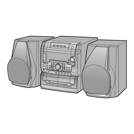
CD-C449W mini component system consisting of
CD-C449W mini component system and
CP-C449 speaker system.
CD-K449W mini component system consisting of
CD-K449W mini component system and
CP-C449 speaker system.
• In the interests of user-safety the set should be restored to its
original condition and only parts identical to those specified be
used.
CD-K449W
This document has been published to be used
for after sales service only.
- 1 -
The contents are subject to change without notice.
CD-C449W/K449W
No.S8875CDC449W/
Page
Advertisement
Table of Contents

Related Manuals for Sharp CD-C449W


Summary of Contents for Sharp CD-C449W
-
Page 1: Table Of Contents
CD-C449W/K449W SERVICE MANUAL No.S8875CDC449W/ CD-C449W CD-K449W CD-C449W mini component system consisting of CD-C449W mini component system and CP-C449 speaker system. CD-K449W mini component system consisting of CD-K449W mini component system and CP-C449 speaker system. • In the interests of user-safety the set should be restored to its... -
Page 2: Safety Precaution For Service Manual
CD-C449W/K449W SAFETY PRECAUTION FOR SERVICE MANUAL WARNINGS THE AEL (ACCESSIBLE EMISSION LEVEL) OF THE LASER POWER OUTPUT IS LESS THAN CLASS 1 BUT THE LASER COMPONENT IS CAPABLE OF EMITTING RADIATION EXCEEDING THE LIMIT FOR CLASS 1. THEREFORE IT IS IMPORTANT THAT THE FOLLOWING PRECAUTIONS ARE OBSERVED DURING SERVICING TO PROTECT YOUR EYES AGAINST EXPOSURE TO THE LASER BEAM. -
Page 3: Specifications
CD-C449W/K449W SPECIFICATIONS CD-C449W/K449W General Cassette deck section Power source: AC 110/127/220/230-240 V, Frequency response: 50-14,000 Hz (Normal tape) Signal/noise ratio: 55 dB (TAPE 1, playback) 50/60 Hz 50 dB (TAPE 2, recording/ Power consumption: 120 W playback) Dimensions: Width; 270 mm (10-5/8") Wow and flutter: 0.15 % (WRMS) - Page 4 CD-C449W/K449W SPECIFICATIONS CD-C449W/K449W General Cassette deck section Power source: AC 110/127/220/230-240 V, Frequency response: 50-14,000 Hz (Normal tape) Signal/noise ratio: 55 dB (TAPE 1, playback) 50/60 Hz 50 dB (TAPE 2, recording/ Power consumption: 120 W playback) Dimensions: Width; 270 mm (10-5/8") Wow and flutter: 0.15 % (WRMS)
-
Page 5: Names Of Parts
CD-C449W/K449W NAMES OF PARTS CD-C449W/K449W Front panel (CD) Disc Tray (CD) Disc Number Select Buttons (CD) Disc Skip Button (CD) Open/Close Button (CD) Disc Number Indicators SRS Indicator (TAPE 2) Direction Indicators (TAPE 2) Reverse Mode Indicator 6 7 8... - Page 6 CD-C449W/K449W (TAPE 1) Cassette Compartment (TAPE 2) Cassette Compartment Rear panel CD Digital Output Socket Video/Auxiliary (Audio Signal) Input Sockets Span Selector Switch FM 75 Ohms Aerial Terminal Aerial Earth Terminal SW1/SW2/MW Aerial Terminal AC Voltage Selector AC Power Lead...
- Page 7 CD-C449W/K449W Remote control Remote Control Transmitter LED CD control section Disc Number Select Buttons Track Down/Review Button Track Up/Cue Button Disc Skip Button Play/Repeat Button Stop Button Memory Button Clear Button Random Button Pause Button Tuner control section Preset Up/Down Buttons...
-
Page 8: Operation Manual
CD-C449W/K449W OPERATION MANUAL SETTING THE CLOCK Press the ON/STAND-BY button to enter the stand-by mode. In this example, the clock is set for the 24-hour Press the CLOCK button. (0:00) system. Within 5 seconds, press the MEMORY button. Jog dial Turn the jog dial to select the time display mode. - Page 9 CD-C449W/K449W – 8 –...
-
Page 10: Disassembly
CD-C449W/K449W DISASSEMBLY Caution on Disassembly CD-C477W/K449W Follow the below-mentioned notes when disassembling the unit and reassembling it, to keep it safe and ensure excellent performance: ( A1 ) x2 Top Cabinet ø3 x12mm 1. Take cassette tape and compact disc out of the unit. - Page 11 CD-C449W/K449W (L1)x2 CD Switch PWB Front Panel (F4) x2 Washer ø3x10mm (E1) x1 Front Panel (F2) x1 (L2)x1 ø3 x10mm (M1)x3 (F3) x2 (F3) x2 Display ø3x10mm (F2) x2 CD-K449W (F1) x1 Only (L3)x12 Headphones (F4) x1 ø3x10mm ø3x10mm Rear...
- Page 12 CD-C449W/K449W ( U1 ) x4 CP-C449 ø3 x12mm Tweeter ( V1 ) x1 Baffle Board ø2.6 x10mm (A2)x1 Shift Lever (A1)x1 CD Changer Mechanism Woofer CD Player Base CD Mechanism Be careful when installing the CD changer mechanism. Install the CD changer mechanism on the CD player base after Screw driver the shift lever has been set in the highest position.
-
Page 13: Removing And Reinstalling The Main Parts
CD-C449W/K449W REMOVING AND REINSTALLING THE MAIN PARTS CD MECHANISM SECTION Perform steps 1, 2, 3,15,16,17 and 19 of the disassembly method to remove the CD mechanism. Loading / Up / Down Motor How to remove the loading motor (See Fig. 12-1) Motor 1. -
Page 14: Adjustment
CD-C449W/K449W ADJUSTMENT TUNER SECTION MECHANISM SECTION • Driving Force Check fL: Low-range frequency fH: High-renge frequency Torque Meter Specified Value • AM IF/RF Play: TW-2412 Tape 1: Over 80 g Signal generator: 400 Hz, 30%, AM modulated Tape 2: Over 80 g... - Page 15 CD-C449W/K449W • FM RF Signal generator: 1 kHz, 40 kHz dev, FM modulated • FM Detection Test Stage Frequency Frequency Setting/ Signal generator: 10.7 MHz, FM sweep Instrument Display Adjusting Connection Frequency Frequency Setting/ Test Stage Instrument Parts Display Adjusting...
-
Page 16: Test Mode
CD-C449W/K449W TEST MODE • Setting the test mode Any one of test mode can be set by pressing several keys as follows. <REC. PAUSE> + <DISC. SKIP> + <POWER> TEST: CD operation test • TEST mode Function — CD test mode Setting of TEST mode Indication of CD TST mode (Fig. - Page 17 CD-C449W/K449W (Continued) SRS ( ) 3D SURROUND About SRS ( ) 3D surround: SRS is a breakthrough technology that creates 3-dimensional sound by processing sound signals based on the human auditory MODE system. It produces real depth and localization of the sound image which cannot be accomplished by ordinary stereo.
-
Page 18: Notes On Schematic Diagram
CD-C449W/K449W NOTES ON SCHEMATIC DIAGRAM • The indicated voltage in each section is the one measured • Resistor: by Digital Multimeter between such a section and the chas- To differentiate the units of resistors, such symbol as K and sis with no signal given. - Page 19 CD-C449W/K449W NOTES ON SCHEMATIC DIAGRAM • The indicated voltage in each section is the one measured • Resistor: by Digital Multimeter between such a section and the chas- To differentiate the units of resistors, such symbol as K and sis with no signal given.
-
Page 20: Waveforms Of Cd Circuit
CD-C449W/K449W WAVEFORMS OF CD CIRCUIT STOP PLAY FOCUS SERCH 0.5ms 0.50 V 10.0 V IC1 20 F.E 0.5ms 10.0 V 0.5ms 5.0 V 0.50 V IC1 54 DRF 0.5ms 1.00 V PLAY 0.5ms NORMAL DISC 1.00 V TN0=01 20ms 1.00 V 0.5ms... -
Page 21: Block Diagram
CD-C449W/K449W Figure 19 BLOCK DIAGRAM (1/3) – 19 –... - Page 22 CD-C449W/K449W FM BAND PASS FILTER SO301 ANTENNA BFT01 TERMINAL ICT01 FM IF FM IF TA7358AP TT01 CF302 AM IF AM IF FM FRONT END CF352 T351 FM IF IN IC303 LT01 LT02 LA1832 VR351 FM MUTE LEVEL FM IF DET./FM MPX./AM IF...
- Page 23 CD-C449W/K449W VF1 (AC) FD01 FL DISPLAY LEDD23~LEDD28 LEDD01~LEDD21 VF2 (AC) RXD01 REMOTE CONTROL SENSOR ICD01 IX0243AW DATA1 KEY MATRIX FL DRIVER & COM1 SWD01~SWD03 CONTROLLER SCK1 SWD07~SWD18 SWD21~SWD22 SWD30~SWD43 KEY IN SWD48 SWD50~SWD54 TUNER MUTE SWD49(CD-K449W ONLY) SWD01 SWD02 JOG DIAL...
- Page 24 CD-C449W/K449W 0.01 47/16 KTA1266 1/50 0.01 4.7K 0.001 4.7/50 CNS1B 2.5V FIN2 CNS1A FIN1 2.5V 2.5V FEBAL 2.5V FOSTA 2.5V TOSTA DGND C4 0.1/50 2.5V 2FREQ 2.5V TE– LASER 2.5V FSTA 2.5V 2.5V LA9241M 0.001 8/12CM TESI 2.2K 0.033 0.033 SERVO AMP.
- Page 25 CD-C449W/K449W CD SIGNAL 0.01 TEST1 DEFI EFLG µ-COM SUB-CODE SBSY INTERFACE XVSS 0V PDO LC78622K R51 3.3M X-TAL VVSS SERVO/SIGNAL GENERATOR XOUT CONTROL XVDD 0.047 1SS133 2K x8BIT 0.033 ISET 2.2V 0.022 1SS133 MUTER VCO CLOCK ERROR CORRECT VVDD RVDD...
- Page 26 CD-C449W/K449W GND(CD2) GND(CD1) GND(D) GND(D) +7.3V(CD) GND(D) +12V(M) +4.6V(D) +4.6V(D) +4V(µ-C +12V(M) GND(µ COM1 RESET CD-K449W CG61 DATA1 ONLY 0.022 RG11 CNSD01 SCK1 CD-K449W ONLY TO DISPLAY PWB DG06 P30 1-D RG23 CG07 1SS133 22/25 RG05 10/100 RG10 SWF02 SPAN...
- Page 27 CD-C449W/K449W CD GND(D2) CD GND(D2) CD GND(D1) CD GND(D1) GND(D) GND(D) +7.3V(CD) +7.3V(CD) +12V(M) +12V(M) +4.6V(D) +4V(µ-CON) +4.6V(D) GND(µ-CON) QG02 DG03 1SS133 KTC3199 GR QG01 KRC102 M CG03 RG37 RG35 RG33 RESET 3.3/50 4.0V POINT RG32 4.0V 4.0V S-MUTE RG34...
- Page 28 CD-C449W/K449W 3.7V RS34 RS33 CS12 CS11 100K 100K 2.2/50 2.2/50 QS14 KRC107 M CS13 IN(L) 100/16 IN(R) CS21 RS11 4.7/50 OUT(L) RS16 OUT(R) RS12 CS22 QS15 4.7/50 GND(A) KTC3203 Y 12.6V 11.9V +12V(A) RS20 RS22 ICS01 QS13 SRS PASS KRC107 M...
- Page 29 CD-C449W/K449W MAIN PWB-A(2/4) CS12 2.2/50 RS16 RS36 RS35 4.7K QS18 2SK246 GR 5.9V 5.9V 5.9V QS17 2SK246 GR 5.9V DS01 CS19 DS02 1SS133 0.33/50 1SS133 RS32 FM SIGNAL 1.5K QS16 5.9V 2SK246 GR 5.9V DS03 1SS133 DIGITAL-OUTPUT CNPR11 2.2µH 1...
- Page 30 CD-C449W/K449W PLAYBACK SIGNAL RECORD SIGNAL QL11 KTA1266 GR 0.26V 0.26V QL17 KRC104 M RL11 RL12 TAPE MECHANISM ASSEMBLY 2.2K RL13 6.8K 0.26V 0.26V QL13 KRC104 M RL14 TAPE MICHANISM PWB–H 3.8V QL14 QL12 KTA1266 GR KTA1273 Y FWM2 12.6V QL18 KRC104 M 0.26V...
- Page 31 CD-C449W/K449W MAIN PWB-A(4/4) 04 M TA2F/R SPEED TA_F/R SPEED QL18 KRC104 M TA2MOT2SW TA_MOT_SW 12.5V M212V M_12V TA2SOL TA_SOL QL19 12.5V KRC104 M T22A2FP T2_A_FP TA2CAM2SW TA_CAM_SW M2GND M_GND T12RUN DL11 T1_RUN 1SS133 RL24 3.3K T22RUN 4.1V T2_RUN QL16 CL13...
- Page 32 CD-C449W/K449W FM SIGNAL RV91 JV91 HEADPHONE HP-LCH RV92 CV91 GND(A) HP-RCH CV92 GND(M) LV91 2.2µH(XH) H/P SW RD48 (YELLOW) LEDD01 QD01 FWV91 1.2K F-PLAY KL052UL KRC107 M WTV11 (YELLOW) LEDD02 RD49 TO SPEAKER QD02 HEADPHONES PWB-C3 STOP KL052UL 1.2K KRC107 M AMP.2 PWB...
- Page 33 CD-C449W/K449W FLD01 FL DISPLAY 10 11 12 13 14 15 16 17 18 19 20 21 22 23 24 25 26 27 29 30 31 32 33 34 35 36 37 38 39 40 41 42 43 44 45 46 47 –29(VP)
- Page 34 CD-C449W/K449W FM SIGNAL MW/SW1/SW2 SIGNAL R310 VD302-B KV1236Z23F T304 C306 Q309 SW2 ANT R311 D305 10P (UJ) 2SC2878 B C303 R312 100K 1SS135 0.022 D309 C309 1SS135 330P TC302 C308 (UJ) C304 R314 TRACKING 0.022 3.3K 8.2P D306 C312 0.022...
- Page 35 CD-C449W/K449W TUNER PWB-E Q365 KRC107 M C343 15P (CH) C342 R358 0.022 8.2K R363 TP 302 VR351 1.5K 10K(B) L353 M MUTE C371 R361 EVEL 1/50 5.6K MUTING R350 Q353 2.7K KTC3199 GR C367 C372 R362 L356 0.65V 1/50 1/50 5.6K...
- Page 36 CD-C449W/K449W QV13 KTC3200 GR 3.9V DV13 FM SIGNAL 1SS133 RV27 CV25 CV11 CV13 RV17 0.022 2.2/50 2.2/50 RV29 ICV01 0.2(1W) CV17 POWER AMP. STK407-09 DV15 1SS133 42.1V 3.9V RV69 0.2(1W) 41.1V QV18 KTC3199 GR CV21 RV23 3.9V RV35 2.2K RV36...
- Page 37 CD-C449W/K449W SPEAKER AMP.PWB-F TMV01 RLYV11 DV15 SPEAKER 1SS133 3.9V CV31 L-CH 0.1(ML) QV18 RV41 KTC3199 GR – 8OHMS 3.9V CV33 0.1(ML) QV19 KTC3199 GR SPEAKER DV17 R-CH 1SS133 CV28 RV40 RV43 47/50 – 4.7(1/2W) RV44 RV42 4.7(1/2W) FAN MOTOR RV55...
- Page 38 CD-C449W/K449W TO MAIN PWB CNPU02 P25 12 - E FM SIGNAL KARAOKE PWB-L CD-K449W ONLY GND(D) R669 R670 C677 47/25 ZD631 MTZJ5.6B R668 1.2K R667 VOLTAGE 6.4V REGULATOR 5.4V Q631 KTC3203 Y C674 4.7V 47/25 C673 0.022 C672 47/25 DIGITL...
- Page 39 CD-C449W/K449W SOLENOID SOLM2 CD MOTOR PWB-K SLED MOTOR SENSOR PWB-J PICK UP IN T/T UP/ CNS3A CNS3B DISC NUMBER DOWN LOADING SPINDLE MOTOR PICKUP UNIT(306) BIM5 CNS1A CNS1B OPEN/CLOSE MECHA UP CNS2A CNS2B 9 8 7 6 5 4 3 2 1...
- Page 40 CD-C449W/K449W FROM SPEAK AMP PWB P44 3-A TO TUNER PWB P42 1-B CNWV1 CNP303 1 2 3 4 5 6 7 8 9 10 11 MAIN PWB-A RP18 RP20 CP24 CP08 RP26 CP23 RP22 RP25 RP12 ICP11 RP11 QP11 QG04...
- Page 41 CD-C449W/K449W FROM SPEAKER AMP PWB P44 3-A R PWB CNWV11 CK52 RK64 RK62 FWP01 RK65 QK24 B C E RK60 CK62 RK61 7 8 9 10 11 QK09 QK25 RK03 RK04 RK06 QK26 QK14 RK42 CK36 CK38 CFWP02 RK24 RK22...
- Page 42 CD-C449W/K449W FLD0 CD11 CD10 CD09 3 4 5 6 7 8 9 10 11 12 13 14 15 16 17 18 19 20 21 22 23 24 CD06 FLHLD CD05 SWD01 VOLUME JOG RXD01 REMOTE CONTROL LD01 SWD03 X-BASS RD53...
- Page 43 CD-C449W/K449W DISPLAY PWB-C1 FLD01 SWD43 RD44 46 47 8 19 20 21 22 23 24 25 26 27 28 29 30 31 32 33 34 35 36 37 38 39 40 41 42 43 44 45 RD43 RD42 RE51 RE41...
- Page 44 CD-C449W/K449W C315 Figure 42 WIRING SIDE OF P.W.BOARD (6/9) – 42 –...
- Page 45 CD-C449W/K449W KARAOKE PWB-L CNSU02 CD-K449W ONLY C622 TO MAIN PWB CNPU02 C623 P39 8-H C620 C632 C621 D601 C627 C602 C626 IC601 C601 C615 C677 C634 C672 C673 R667 R601 R668 R602 C674 ZD631 COLOR TABLE BROWN VR603 VR602 VR601...
- Page 46 CD-C449W/K449W TO MAIN PWB P39 7-A FROM CFWP01 HEADPHONES PWB FROM FAN MOTOR P40 2-F P37 8-G FWP01 FWV91 CNSV11 WTV11 QV22 CNPV11 RV61 QV19 RY21 RV62 RV58 CV49 DV20 CNPV12 FROM POWER PWB P45 12-G QV21 CV11 CNS903 CV12...
- Page 47 CD-C449W/K449W SW991 VOLTAGE SELECT (285) AC POWER SUPPLY AC 110/127/220/230-240V 50/60Hz (285) (242) COLOR TABLE T.F. BROWN RD(R) ORANGE YELLOW GREEN BLUE VIOLET GRAY WH(W) WHITE BLACK PINK D951 D952 WTP02 D953 TO MAIN PWB D954 C959 R957 R956 C958...
-
Page 48: Troubleshooting
CD-C449W/K449W TROUBLESHOOTING When the CD does not function When the CD section does not operate When the objective lens of the optical pickup is dirty,this section may not operate.Clean the objective lens,and check the playback operation.When this section does not operate even after the above step is taken,check the following items. - Page 49 CD-C449W/K449W • When the CD tray fails to open or close. Is there following voltage input in specific state of ICF01 pin 93? Check the OPEN CLOSE SW and the wiring from the ICF01 pin 93 to the OPEN CLOSE SW.
- Page 50 CD-C449W/K449W • Playback can only be performed when a disc is loaded. Check the laser diode driver. Is the Focus servo active? (Can you hear it working?) Check the area around IC1(16) - (21) (focus servo circuit). If the disc is not turning, the DRF Does the DRF signal change from "L"...
- Page 51 CD-C449W/K449W • Checking the spin system. Play operation is performed without disc. The turntable rotates a little. The spin driver circuit is normal. Check the periphery of IC1 pins 23 to 27, pin 39, and pin 40, IC2 The turntable fails to rotate or rotates at high speed.
-
Page 52: Function Table Of Ic
CD-C449W/K449W FUNCTION TABLE OF IC IC2 VHiLC78622K-1: Servo/Signal Control (LC78622K) (1/2) Terminal Name Input/Output Pin No. Function DEFI Input Input terminal of defect detection signal (DEF). (Connected to OV when not used.) Input For PLL Input terminal for test. Pull-down resistor is integrated. Surely connected to 0V. - Page 53 CD-C449W/K449W IC2 VHiLC78622K-1: Servo/Signal Control (LC78622K) (2/2) Terminal Name Input/Output Pin No. Function Output Output terminal of subcodes P, A, R, S, T, U and W. SFSY Output Output terminal of synchronous signal of subcode frame. It drops when subcode stands by.
- Page 54 CD-C449W/K449W IC1 VHiLA9241M/-1: Servo Amp. (LA9241M) (1/2) Function Port Name Pin No. FIN2 Connection pin for photodiode of pickup. RF signal is generated through addition with FIN pin, and FE signal is generated through subtraction. FIN1 Connection pin for photodiode of pickup.
- Page 55 CD-C449W/K449W IC1 VHiLA9241M/-1: Servo Amp. (LA9241M) (2/2) Function Port Name Pin No. Micro computer command clock input pin. Micro computer command data input pin. Micro computer command chip enable input pin. (DETECT RF) RF level detection output. (Focus Serch Select) Pin to switch focus search mode. (± search/+ search for reference voltage) VCC2 VCC pin for servo system and digital system.
- Page 56 CD-C449W/K449W ICF01 RH-iX0235AWZZ:System Microcomputer (IX0235AW) Pin No. Port Name Input/Output Function P00-P01 Input/Output 8-Bit input/output port. Input/output can be specified in 4-bit units HOLD release input. Port 0 interrupt input 3-10 P10-P17 Input/Output 8-Bit input/output port. Input/output can be specified in 1-bit units...
- Page 57 CD-C449W/K449W ICD01 RH-iX0234AWZZ:System Microcomputer (IX0234AW) (1/2) Input/Output Pin No. Port Name Function P16-P17 Input/Output 8-Bit input/output port. Input/output can be specified in 1-bit units (1*,2) Dual-purpose function P16: BUZ output P17: Timer 1 output (PWM output) 3-10 P30-37 Input/Output 8-Bit input/output port. Input/output can be specified in 1-bit units...
- Page 58 CD-C449W/K449W ICD01 RH-iX0234AWZZ:System Microcomputer (IX0234AW) (2/2) Input/Output Pin No. Port Name Function 64-71 S32-S39 Input/Output Fluorescent charcater display tube (VFD)display controller Segment output Dual-purrpose function S32: High voltage withstand input port PE0 S33: High voltage withstand input port PE1 S34: High voltage withstand input port PE2...
-
Page 59: Fl Display
CD-C449W/K449W FLD01 : VVKBJ614GK/-1 FL Display (2G) (1G) – – – – – – – – – – – – – – – – – – – – – – – – – – – – – – – –...