Table of Contents
Advertisement
Quick Links
Group Remote Controller
(Compact group controller)
RBP-RC001-E
Installation & Owner's Manual
● Thank you for purchasing this group remote controller.
● In order to use this product safely and correctly, please read this Installation & Owner's Manual
carefully before use and make sure that you fully understand the contents.
In particular, please be sure to read the "Safety Precautions".
● After reading this manual, be sure to keep it in a place where the operator of the Unit can always
view it.
● This product uses bitmap fonts manufactured and sold by Ricoh Industrial Solutions Inc.
99NA32RCAISEN22B
32RCA001TS-02ISEN
For commercial use
Advertisement
Table of Contents

Related Manuals for Toshiba RBP-RC001-E


Summary of Contents for Toshiba RBP-RC001-E
- Page 1 For commercial use Group Remote Controller (Compact group controller) RBP-RC001-E Installation & Owner's Manual ● Thank you for purchasing this group remote controller. ● In order to use this product safely and correctly, please read this Installation & Owner's Manual carefully before use and make sure that you fully understand the contents.
-
Page 2: Table Of Contents
Contents Safety Precautions ........................4 Specifications ..........................6 Product specifications ......................6 Outline Drawing ........................6 Names of each part ......................7 Included Items ........................7 Wiring specifications ......................7 Screw size of each terminal ....................7 Installation ............................. 8 Power, Signal, Earth and Communication Line Connections .......... - Page 3 Setting Items ..........................29 Operation Pattern Settings....................30 Schedule Settings ....................... 34 Display Settings ........................37 Button Settings ........................38 Date&time setting ....................... 39 I/O settings .......................... 40 Language Setting ........................ 41 DN code setting ........................41 Maintenance Items ........................42 Product Info.
-
Page 4: Safety Precautions
RBP-RC001-E Installation & Owner's Manual 32RCA001TS-02ISEN Safety Precautions Installation Precautions • Read these "Safety Precautions" carefully before installation. • The precautions described below include important items regarding safety. Observe them without fail. Understand the following details (indications and symbols) before reading the body text, and follow the instructions. - Page 5 RBP-RC001-E Installation & Owner's Manual 32RCA001TS-02ISEN Usage Precautions Do not operate the switches with wet Do not start or stop the heat source hands. machine by turning on / off the power Doing so may cause electric shock or failure.
-
Page 6: Specifications
RBP-RC001-E Installation & Owner's Manual 32RCA001TS-02ISEN Specifications Product specifications Product name Group Remote Controller Model name RBP-RC001-E Power supply 220 to 240 VAC 50/60 Hz Power consumption Number of connected Up to 2 units (For USX series module controllers) units... -
Page 7: Names Of Each Part
RBP-RC001-E Installation & Owner's Manual 32RCA001TS-02ISEN Names of each part Terminal block for external contact input / output Terminal block for external input / output power supply Communication terminal block Name Function Terminal block for external contact input / Connect the signal wires for external contact input / output... -
Page 8: Installation
RBP-RC001-E Installation & Owner's Manual 32RCA001TS-02ISEN Installation Power, Signal, Earth and Communication Line Connections Connect the power, signal earth and communication lines to the specified terminal blocks. Attach round crimp terminals to all wiring and tighten the screws securely. After tightening, check that the wiring cannot come out. -
Page 9: Power Supply Wire And Ground Wire Connection
RBP-RC001-E Installation & Owner's Manual 32RCA001TS-02ISEN Power supply wire and ground wire connection Connecting the power supply wire and the ground wire (1) Remove 3 cover fixing screws pointed to by arrows and open the cover. (2) Insert cross notches in the rubber bushing in order to pass the power supply cable. -
Page 10: Connecting The Communication Wires
RBP-RC001-E Installation & Owner's Manual 32RCA001TS-02ISEN Connecting the communication wires Communication wire connection procedure RS-485 communication wire has polarity. A: RS-485-A (+) B: RS-485-B (-) G: RS-485-GND Ground the shield of the communication wire to the frame of the group remote controller, and do not ground it on the connected device side (MC side). -
Page 11: Connection To External Equipment
RBP-RC001-E Installation & Owner's Manual 32RCA001TS-02ISEN Connection to External Equipment Output 2 Signal Input / output External Output 1 l ( ) power Input / output supply Input 3 l ( ) input Signal Input 2 Input 1 Example of connection to external equipments... -
Page 12: How To Install
RBP-RC001-E Installation & Owner's Manual 32RCA001TS-02ISEN How to Install CAUTION • Do not wire communication lines or input/output wiring next to power supply wiring, etc, or house them in the same metal pipe. Doing so may result in failure. • Install the group remote controller away from the noise sources. -
Page 13: Clock Setting
RBP-RC001-E Installation & Owner's Manual 32RCA001TS-02ISEN Clock Setting CAUTION • When the power is turned on for the first time or if the power has been shut down for three days or more, the clock may be initialized (to January 1, 2021). If the clock is initialized, the message below appears. Press the [●] (Confirm) button to switch to the Clock Setting screen. -
Page 14: Group Remote Controller Overview
RBP-RC001-E Installation & Owner's Manual 32RCA001TS-02ISEN Group remote controller overview Overview The group remote controller (hereinafter referred to as GR) is a compact group controller that connects the following heat source equipment and instructs the distribution of the water system of the heat source equipment, operation mode, set temperature, and start / stop. -
Page 15: Function List
RBP-RC001-E Installation & Owner's Manual 32RCA001TS-02ISEN Function List Function Remark Run/stop, operation mode, whether failures occurred, operation capacity, outlet/inlet water System status temperatures, unit flow (Note 1), and simplified power (including pump power) Run/stop, operation mode, fault code, operation capacity, outlet/inlet water temperatures,... -
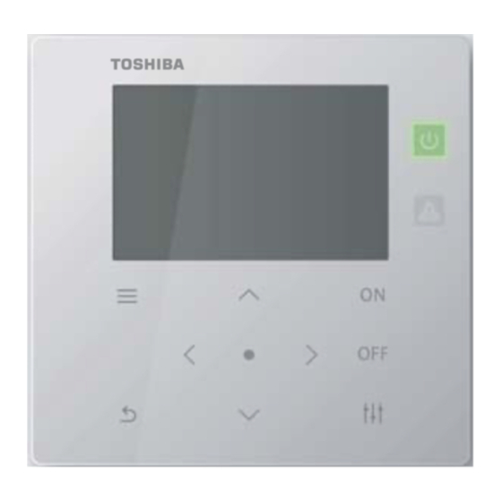
Page 16: Names And Functions Of Parts
RBP-RC001-E Installation & Owner's Manual 32RCA001TS-02ISEN Names and Functions of Parts Operation panel Name Description (Note 1) – ON during running and OFF during stoppage. Operation lamp You can change the output method by setting “Level of operating output”. (Note 2) Lights up when a failure occurs. -
Page 17: Icon List
RBP-RC001-E Installation & Owner's Manual 32RCA001TS-02ISEN Icon List Item Icon Status Description Unit Indicates that the GR is set to Unit. Unit/External External Indicates that the GR is set to External. Stop Indicates the stopped state. Run/Stop Indicates the running state. -
Page 18: Screen Structure
RBP-RC001-E Installation & Owner's Manual 32RCA001TS-02ISEN Screen Structure All information (P. 21) GR operation (P. 23) • Switching between Unit and External • Information about each • Switching between operation patterns system • Schedule ON/OFF [●] System information (P. 21) System operation (P. - Page 19 RBP-RC001-E Installation & Owner's Manual 32RCA001TS-02ISEN Menu (P. 29) Failure History (P. 27) • Display of past failure dates and times, fault codes, and failure descriptions Setting (P. 29) Operation Pattern Settings(P. 30) • Setting of each operation pattern Schedule Settings (P. 34) •...
-
Page 20: Basic Operations
RBP-RC001-E Installation & Owner's Manual 32RCA001TS-02ISEN Basic Operations Inputting a password Select “Setting” or “Maintenance” from the Menu screen to display the Input Password screen. If no password is set, press [●] (Confirm) without changing the digits. If you input an incorrect password, an error message appears and the functions are restricted. -
Page 21: Displaying The Operation Status
RBP-RC001-E Installation & Owner's Manual 32RCA001TS-02ISEN Displaying the Operation Status The operation state appears on the “all information screen”, “system information screen”, “MC information screen”, “UC information screen”, and “circuit information screen”. For details of the items displayed on each operation status display screen, refer to “14-1List of display items on information screens (P. -
Page 22: Mc Information
RBP-RC001-E Installation & Owner's Manual 32RCA001TS-02ISEN MC Information Displays the current operating state of the system. Displays the operation mode of the system. Displays the operation pattern of the system. Displays the current system number. You can switch the displayed item to another, using [Λ] and [V]. -
Page 23: Operating Methods
RBP-RC001-E Installation & Owner's Manual 32RCA001TS-02ISEN Operating Methods Switching the group remote controller between Run/Stop and switching between operation patterns To switch the GR between Run/Stop and switch between operation patterns, use a unit operation or an external signal. Which of a unit operation or an external signal to use for switching differs depending on the Unit/External and input/output function settings of the GR, as in the table below. - Page 24 RBP-RC001-E Installation & Owner's Manual 32RCA001TS-02ISEN In the case of external operation (when Run/Stop input is set) Switch the current operating state of the GR with an external Run/Stop input signal. The unit operation (ON button operation) is disabled. During running with an external signal, performing a unit stop operation (OFF button operation) causes a message to be displayed, so that you can switch to unit stop.
-
Page 25: System Operation
RBP-RC001-E Installation & Owner's Manual 32RCA001TS-02ISEN System operation When set to Link, a system runs/stops in link with the current operating state of the GR. When set to Individual, a system is operated on the system operation screen. For information about switching between Link and Individual, refer to P. 26. - Page 26 RBP-RC001-E Installation & Owner's Manual 32RCA001TS-02ISEN Changing the system operation settings System operation screen On the system information screen, press [ ] to display the system operation screen. Use [<] and [>] to select the item to change. For information about how to set each item, refer to the table below.
-
Page 27: Displaying Failure History
RBP-RC001-E Installation & Owner's Manual 32RCA001TS-02ISEN Displaying Failure History You can display Failure History of the GR and MCs, up to 16 records for each (48 records in total). In Failure History, the dates and times failures occurred, the numbers of the MCs, UCs, and circuits in which the failures occurred, fault codes, and failure details are displayed. -
Page 28: Clearing Failure History
RBP-RC001-E Installation & Owner's Manual 32RCA001TS-02ISEN Clearing Failure History Failure History screen Press [●] (Clear) and on the message screen, press [●] (Confirm). Failure History of the failures detected by the GR is cleared. * You cannot clear the Failure History of MCs from the GR. -
Page 29: Setting Items
RBP-RC001-E Installation & Owner's Manual 32RCA001TS-02ISEN Setting Items ■ Displaying the “Setting” screen Press [ ] to display the Menu screen. On the Menu screen, select “Setting” and press [●] (Confirm). The Input Password screen appears. Input a 4-digit password and press [●] (Confirm). -
Page 30: Operation Pattern Settings
RBP-RC001-E Installation & Owner's Manual 32RCA001TS-02ISEN Operation Pattern Settings An MC (MC system) and UC system assignment for each GR system, operation mode, set temperature, demand setting, sensor setting, and pattern link output can be collected into a single operation pattern. You can set up to 4 operation patterns. - Page 31 RBP-RC001-E Installation & Owner's Manual 32RCA001TS-02ISEN Operation Settings Set the operation conditions for each GR system. Operation settings screen Set temperature input screen Demand value input screen List of “Operation Settings” setting items Item Description MC Gr.Ctrl Set MC group control to ON/OFF.
- Page 32 RBP-RC001-E Installation & Owner's Manual 32RCA001TS-02ISEN System Settings Assign the GR system for the A/B systems of an MC. Use [<] and [>] to select “System Settings” and press [●] (Confirm). Use [Λ] and [V] to select the item to change and press [●] (Confirm).
- Page 33 RBP-RC001-E Installation & Owner's Manual 32RCA001TS-02ISEN Sensor setting You can set the system for a control sensor. Use [<] and [>] to select “Sensor setting” and press [●] (Confirm). Use [Λ], [V], [<], and [>] to select the item to change and press [●] (Confirm).
-
Page 34: Schedule Settings
RBP-RC001-E Installation & Owner's Manual 32RCA001TS-02ISEN Schedule Settings Before making Schedule Settings, be sure to set the clock. No schedules will operate in any of the following cases: The clock is not set. Schedules are disabled with the Schedule Settings. - Page 35 RBP-RC001-E Installation & Owner's Manual 32RCA001TS-02ISEN Week Events From the GR, you can automatically perform events (Run/Stop) at each event time. You can set up to 6 events a day. If Run/Stop inputs (static signal) are set externally, the external signals are prioritized.
- Page 36 RBP-RC001-E Installation & Owner's Manual 32RCA001TS-02ISEN Special Events [CAUTION] If you want to operate a schedule with Special Events, set Special1 to Special3 on “Schedule (P. 34)”. Use [Λ] and [V] to select “Special Events” and press [●] (Confirm). Use [<] and [>] to select the desired special day and press [●] (Confirm).
-
Page 37: Display Settings
RBP-RC001-E Installation & Owner's Manual 32RCA001TS-02ISEN Display Settings On the setting screen, select “Display Settings” and press [●] (Confirm). Use [Λ] and [V] to select an item and press [●] (Confirm). Contrast Select “Contrast” and press [●] (Confirm). Use [<] and [>] to move the ▲. -
Page 38: Button Settings
RBP-RC001-E Installation & Owner's Manual 32RCA001TS-02ISEN Button Settings On the setting screen, select “Button Settings” and press [●] (Confirm). Use [Λ] and [V] to select an item and press [●] (Confirm). Sound Setting Select “Sound Setting” and press [●] (Confirm). -
Page 39: Date&Time Setting
RBP-RC001-E Installation & Owner's Manual 32RCA001TS-02ISEN Date&time setting Date&time setting enables you to change the year, month, day, hours, and minutes. Be sure to set the time so that it can be recorded in failure history and saved operation data. -
Page 40: I/O Settings
RBP-RC001-E Installation & Owner's Manual 32RCA001TS-02ISEN I/O settings You can assign functions for external inputs such as operation patterns and demand signals, as well as functions for external signal outputs such as operation signals and failure signals. Make sure that no digital noise is applied to the external I/O wiring. -
Page 41: Language Setting
RBP-RC001-E Installation & Owner's Manual 32RCA001TS-02ISEN Language Setting On the setting screen, select “Language Setting” and press [●] (Confirm). Use [Λ] and [V] to select a language. To confirm the changes, press [ ] (Return) and on the message screen, press [●] (Confirm). -
Page 42: Maintenance Items
RBP-RC001-E Installation & Owner's Manual 32RCA001TS-02ISEN Maintenance Items ■ Displaying the “Maintenance” screen Press [ ] to display the Menu screen. On the Menu screen, select “Maintenance” and press ■ [●] (Confirm). The Input Password screen appears. Input a 4-digit maintenance password and press [●] (Confirm). -
Page 43: Product Info
RBP-RC001-E Installation & Owner's Manual 32RCA001TS-02ISEN Product Info. On the Maintenance screen, select “Product Info.” and press [●] (Confirm). The Model, Serial No., Software No., and OS No. are displayed. Check of I/O Check of Digital Input You can check the function that is set for each terminal and its state. -
Page 44: Password Setting
RBP-RC001-E Installation & Owner's Manual 32RCA001TS-02ISEN Password Setting You can change the setting password and the maintenance password. You can change the setting password and the maintenance password with the same procedure. On the Maintenance screen, select “Password Setting” and press [●] (Confirm). -
Page 45: List Of Display/Setting Items
RBP-RC001-E Installation & Owner's Manual 32RCA001TS-02ISEN List of Display/Setting Items List of display items on information screens A list of items to display on each information screen is provided below. Apart from the items in the note below, some items are not displayed or displayed as “---”... - Page 46 RBP-RC001-E Installation & Owner's Manual 32RCA001TS-02ISEN System information screen Model Item Description Fault code Displays the 6-digit fault code of the failure that has occurred in the GR system. 123456 | | | | 56- Fault code | | | 4 - - - Failed circuit No.
- Page 47 RBP-RC001-E Installation & Owner's Manual 32RCA001TS-02ISEN MC information screen Model Item Description Fault code Displays the 5-digit fault code of the failure that has occurred in the MC system. 12345 | | | 45- Fault code | | 3 - - - Failed circuit No.
- Page 48 RBP-RC001-E Installation & Owner's Manual 32RCA001TS-02ISEN UC information screen Model Item Description Displays the 3-digit fault code of the failure that has occurred in the UC. Fault code ● ● ● ● ● | 23 - Fault code 1 - - - Failed circuit No.
- Page 49 RBP-RC001-E Installation & Owner's Manual 32RCA001TS-02ISEN Circuit information screen Supported model Item Description Comp. Displays the ON/OFF state of the compressor. ● × ● ● ● H prss Displays the high pressure. ● × ● ● ● L prss Displays the low pressure.
-
Page 50: I/O Function List
RBP-RC001-E Installation & Owner's Manual 32RCA001TS-02ISEN I/O function list Digital Input functions Setting Initially set Function name Details classification terminal No. ― ― No function Not set Used to perform Run/Stop operations with external static signals. Run/Stop input signal (Note 1) Stop input (pulse) Used to perform a Stop operation with an external pulse signal. -
Page 51: Dn Code List
RBP-RC001-E Installation & Owner's Manual 32RCA001TS-02ISEN DN code list Initial DN code Item Description Restart value Switches operation input to pulse signal input. 0: Static signal Static or pulse neces- 1: Pulse signal operation signal sary Enable fault reset when GR is externally stopped. - Page 52 RBP-RC001-E Installation & Owner's Manual 32RCA001TS-02ISEN Initial DN code Item Description Restart value Sets the lower limit flow for the inlet/outlet average temperature calculation for the system based on the quantity of heat. In the constant flow region, MC in/out temp Min the average temperature may be shifted due to a flow error.
-
Page 53: When You Suspect A Failure
When You Suspect a Failure If a failure occurs in the product, do not attempt to repair it yourself. Contact your dealer or local Toshiba Carrier representative. Let us know the model, fault code, and contact No. (For the contact No., refer to the label attached to the product itself.) The symptoms listed in the table below are not failures. - Page 54 RBP-RC001-E Installation & Owner's Manual 32RCA001TS-02ISEN Date: 202303...