Table of Contents
Advertisement
Quick Links
SPECIFICATIONS
Product Name:
Product Series Name:
Product Model Number:
Motion Control Business Unit, Industrial Device Business Division
7-1-1 Morofuku,Daito-City,Osaka 574-0044,Japan
If you have any questions, please contact the seller (Sales office or Distributor) of the product.
Document No.
Revision No.
Date of Issue
Classification
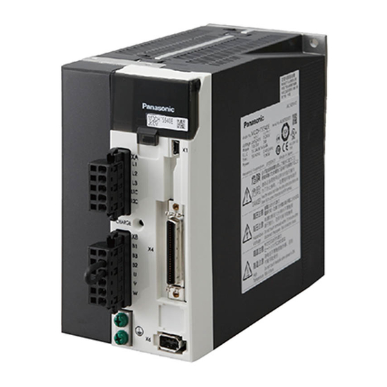
AC servo driver
MINAS-A6 series
DC24 / 48 V type
Panasonic Industry Co., Ltd.
: SX-DSV03167
: 6.0
: July.
19, 2022
: □ New ■ Change
Advertisement
Table of Contents

Related Manuals for Panasonic MINAS-A6 Series


Summary of Contents for Panasonic MINAS-A6 Series
- Page 1 Product Series Name: DC24 / 48 V type Product Model Number: Motion Control Business Unit, Industrial Device Business Division Panasonic Industry Co., Ltd. 7-1-1 Morofuku,Daito-City,Osaka 574-0044,Japan If you have any questions, please contact the seller (Sales office or Distributor) of the product.
- Page 2 Correct the sentence following SX-DSV03025 P.38 Add description of network security P.39 Add description of reverse engineering P.41 Add amplifier list and changed maximum output current Appendix List of Modify the default parameters Default Parameters R6.0 Motion Control Business Unit, Panasonic Industry Co., Ltd.
-
Page 3: Table Of Contents
13. Network Security ..............................38 14. Additional Precautions ............................39 15. Other notes of specification ............................ 40 16. Specifications for each model ..........................41 Appendix List of Default Parameters ..........................42 R6.0 Motion Control Business Unit, Panasonic Industry Co., Ltd. -
Page 4: Scope Of Application
: SX- DSV03283 Technical document - Modbus communication and Block operation Specification - : SX- DSV03042 Please refer to the Panasonic web site for the above documents. Operating Precautions Pay a special attention to following items because the part of internal board is exposed. -
Page 5: How To Read Product Numbers
L : A6 series S: Analog/Pulse Power supply voltage Safety function C: DC 24 V N: No safety function B: DC 48 V Output category Indicates the difference in applicable motors (or output ratings). R6.0 Motion Control Business Unit, Panasonic Industry Co., Ltd. - Page 6 Where applicable, these items are indicated with “Cannot be used in [A6SG]” in the descriptions contained in this reference for your confirmation. For details of Modbus communications and block operations, please refer to Technical reference (Modbus communication and Block operation Specification). R6.0 Motion Control Business Unit, Panasonic Industry Co., Ltd.
-
Page 7: Product Line-Up
DC 24 V MSMF01C△1□2* 100W MQMF01C△1□2* MVDLN5CSF MVDLN5CSG MQMF1EC△1□2* 133W 2000r/min MHMF1EC△1□2* MSMF5AB△1□2* MHMF5AB△1□2* MVDLN4BSF MSMF01B△1□2* MVDLN4BSG MQMF01B△1□2* 100W 3000r/min MHMF01B△1□2* DC 48 V MQMF02B△1□2* 200W MHMF02B△1□2* MVDLN5BSF MVDLN5BSG MQMF2JB△1□2* 266W 2000r/min MHMF2JB△1□2* R6.0 Motion Control Business Unit, Panasonic Industry Co., Ltd. -
Page 8: Specifications
When input power supply voltage is below the rated value (24 V/48 V), overload protection might be triggered even speed and torque are within the rated range at some motor's specifications. R6.0 Motion Control Business Unit, Panasonic Industry Co., Ltd. -
Page 9: Appearance And Name Of Each Part
No. SX-DSV03167 - 6 - 5. Appearance and name of each part Below figure shows a multi-function type. The RS485 communication type is not provided with X5 (external scale connector). R6.0 Motion Control Business Unit, Panasonic Industry Co., Ltd. - Page 10 B000 - B999 17000 - 17999 H000 - H999 18000 - 18999 J000 - J999 22000 - 22999 N000 - N999 23000 - 23999 P000 - P999 33000 - 33999 Z000 - Z999 R6.0 Motion Control Business Unit, Panasonic Industry Co., Ltd.
-
Page 11: Outside Dimensions
Below figure shows a multi-function type. The RS485 communication type is not provided with X5 (external scale connector). Unit: mm * Do not use threaded screw holes that do not have description of dimensions. R6.0 Motion Control Business Unit, Panasonic Industry Co., Ltd. -
Page 12: Configuration Of Connectors And Terminal Blocks
• Connect U phase of the motor winding • Connect V phase of the motor winding • Connect W phase of the motor winding • Connect FG wire of the motor R6.0 Motion Control Business Unit, Panasonic Industry Co., Ltd. -
Page 13: Usb Connector X1
Serial bus transmission and reception data RS485 signal (RS485) 485+ Frame ground shell Frame ground (Note 1) The signal ground GND is connected with the control circuit ground connected with the connector R6.0 Motion Control Business Unit, Panasonic Industry Co., Ltd. -
Page 14: Parallel I/O Connector, X4
Signal ground Analog input (Note 1) Analog output monitor Signal ground Frame ground Pin layout 1 2 3 ・ ・ ・ ・ (Note 1) This function cannot be used with [A6SG]. R6.0 Motion Control Business Unit, Panasonic Industry Co., Ltd. - Page 15 The maximum allowable input voltage is ± 10 V Ai-1 (Note 1) The function changes according to the control mode. (Note 1) This function cannot be used with [A6SG]. R6.0 Motion Control Business Unit, Panasonic Industry Co., Ltd.
- Page 16 Internally connected to the case. Signal ground Signal ground Internally insulated from Control output common (SO-COM). Internally connect to N-pin of power supply connector XA-1 and XA-2. R6.0 Motion Control Business Unit, Panasonic Industry Co., Ltd.
-
Page 17: External Feedback Device Connector X5
Count-down direction Count-up direction EXB is advanced 90° than EXA EXB is retarded 90° than EXA t1 > 0.125 µs t1 > 0.125 µs t2 > 0.5 µs t2 > 0.5 µs R6.0 Motion Control Business Unit, Panasonic Industry Co., Ltd. -
Page 18: Encoder Connector X6
*Note 2) The encoder power output E0V is connected with the control circuit ground that is connected to Pin.1(E5V) of connector X5 and signal ground of connector X4 inside the servo driver. R6.0 Motion Control Business Unit, Panasonic Industry Co., Ltd. -
Page 19: Input / Output Signal Interface
24 V Ω PULS Pins: SIGN +: B7, B8 Note) To directly run the relay, attach a diode in parallel with the relay and in the direction shown in the figure above. R6.0 Motion Control Business Unit, Panasonic Industry Co., Ltd. -
Page 20: Wiring And System Configuration
I/O connection (Note 3) (Note 1) The above wiring length is the maximum value under the evaluation environment of Panasonic. It does not guarantee the operation under the working environment of the customer. The above wiring length is the maximum wiring length including tolerance of processing. -
Page 21: Precautions For Wiring
Below figure don’t shows all pins of each connector. Servo driver XA-1 Main Power Supply DC24 V / 48 V XA-2 Control Power Supply DC24 V / 48 V Green White Black shell EX0V shell Frame R6.0 Motion Control Business Unit, Panasonic Industry Co., Ltd. - Page 22 When using an earth leakage breaker, take measures against high frequency. [8] Brake power supply for the motor with brake should be prepared by customer. [9] Apply power supply voltage after completing wiring. R6.0 Motion Control Business Unit, Panasonic Industry Co., Ltd.
-
Page 23: Wiring To Connector X4
4.7 kΩ 4.7 kΩ 4.7 kΩ 4.7 kΩ SI10 Servo driver The functions of pins A10-A14 should be allocated by parameters. For details, refer to “Technical Reference - Functional Specifications -.” R6.0 Motion Control Business Unit, Panasonic Industry Co., Ltd. - Page 24 DC12 - 24 V SO4+ 10 Ω SO-COM Servo driver The functions of pins A7, A8, B7, B8 should be allocated by parameters. For details, refer to “Technical Reference - Functional Specifications -.” R6.0 Motion Control Business Unit, Panasonic Industry Co., Ltd.
- Page 25 Allowable output voltage range of line driver: 3.1 V ≤ VOH - VOL ≤ 4.7 V If the above condition cannot be satisfied, the input signal may be disturbed and the operation of the servo motor may become unstable. R6.0 Motion Control Business Unit, Panasonic Industry Co., Ltd.
- Page 26 Shorten the wire length (up to 1 m). Be aware that the maximum pulse frequency of the open collector interface is small (200 kpps) compared with that (500 kpps) of the line driver interface. R6.0 Motion Control Business Unit, Panasonic Industry Co., Ltd.
- Page 27 At that time, mount an appropriate terminating resistor (approx. 330 Ω) between the line receiver inputs. [2] The maximum output frequency should be 4 Mpps (after quad edge evaluation) or less. R6.0 Motion Control Business Unit, Panasonic Industry Co., Ltd.
-
Page 28: Wiring To Connector X5
[8] When driving an external scale using external power supply, make the EX5V pin open so that voltage is not supplied to this pin from outside. In addition, connect 0 V (GND) of the external power supply with EX0V (X5 2pin) of the driver to obtain the same electric potential. R6.0 Motion Control Business Unit, Panasonic Industry Co., Ltd. - Page 29 Servo driver Scale Cable Feedback scale unit Wiring example of the serial communication type EX5V EX0V EXPS EXPS (Serial signal) (Serial signal) Detection head Servo driver Feedback scale unit Scale Cable R6.0 Motion Control Business Unit, Panasonic Industry Co., Ltd.
-
Page 30: Wiring To Connector X6
(at least 30 cm). Do not route the wires through the same duct and do not tie them together. Twisted pair +5 V BAT+ Battery (*) BAT- 172169-1 (Tyco electronics) Motor Encoder cable Servo driver (*) When not use absolute system, remove battery. R6.0 Motion Control Business Unit, Panasonic Industry Co., Ltd. - Page 31 If you use battery unit DV0P2990 (built-in battery: ER6V 3.6V made by TOSHIBA LIFESTYLE PRODUCTS & SERVICES), which is an optional item of Panasonic, connect the connector with lead wire to CN601 as shown in the right figure and set it aside for five minutes.
-
Page 32: Dynamic Brake
• As shown below, install the servo amplifier so that the connector XA - 1 faces downward. When other installation directions, use at ambient temperature of 45 ° C or less. R6.0 Motion Control Business Unit, Panasonic Industry Co., Ltd. -
Page 33: Compliance With The International Standards
To comply with the EMC directive, use a noise filter, a surge absorber, and a ferrite core. The compliance of machinery and equipment with the EMC Directive must be confirmed on machinery and equipment in its final state incorporating servo drivers and servo motors. R6.0 Motion Control Business Unit, Panasonic Industry Co., Ltd. -
Page 34: Configuration Of Peripheral Devices
When performing a withstand test for the machines and devices, be sure to remove the surge absorber. Otherwise, the surge absorber may get damaged. 9-3-5 Ferrite core Install the ferrite cores for signal lines in all cables (power supply, motor, encoder, and interface cables). R6.0 Motion Control Business Unit, Panasonic Industry Co., Ltd. -
Page 35: List Of Servo Drivers And Applicable Peripheral Devices
This product is an electromagnetic wave generating device for business use (Class A), which is intended for the use in places other than household. The distributor and the user should be attentive to this point. (Applicable model: Servo Driver) R6.0 Motion Control Business Unit, Panasonic Industry Co., Ltd. -
Page 36: Safety Precautions
(14) Wiring work should be carried out by an electrical engineer. (15) Motors other than that specified do not include protective devices. Protect them using overcurrent protection devices, ground-fault circuit interrupters, overheating prevention devices, emergency stop devices, etc. R6.0 Motion Control Business Unit, Panasonic Industry Co., Ltd. - Page 37 (34) If the motor has a built-in brake, it is for maintenance purposes and should not be used as a stopping (braking) device in order to ensure machine safety. (35) Do not drop or tip over the product during transportation or installation. R6.0 Motion Control Business Unit, Panasonic Industry Co., Ltd.
- Page 38 (38) Do not expose the product to direct sunlight. When storing the product, keep it away direct sunlight and store at temperatures and humidity within the specified ranges. (39) Do not attempt to overhaul or modify the motor. Overhauls must be carried out by Panasonic or an authorized dealer.
- Page 39 If the temperature cannot be measured from a distance of 50 mm, measure at the midpoint of the gap between the obstacle preventing measurement and the servo driver. Operating temperature range: 0 - 55°C R6.0 Motion Control Business Unit, Panasonic Industry Co., Ltd.
-
Page 40: Life Span
As a general rule, you will be responsible for shipping costs. R6.0 Motion Control Business Unit, Panasonic Industry Co., Ltd. -
Page 41: Network Security
・If the product is to be disposed of, transferred, repaired, or otherwise transferred to a third party, important information may also be recorded on the product. At customer's risk, please handle it with care, such as erasing it. R6.0 Motion Control Business Unit, Panasonic Industry Co., Ltd. -
Page 42: Additional Precautions
(17) Do not use detergents containing benzine, thinner, alcohol, acid, or alkaline as this may cause discoloration or damage to the product's exterior. (18) Do not reverse engineer, decompile, or disassemble this product. R6.0 Motion Control Business Unit, Panasonic Industry Co., Ltd. -
Page 43: Other Notes Of Specification
LED status Condition of servo driver Alarm occurs Lighting on LED1 (Red) Normally Lighting off SRVON LED status Condition of servo driver Servo ON Lighting on LED2 (Green) Servo OFF Lighting off R6.0 Motion Control Business Unit, Panasonic Industry Co., Ltd. -
Page 44: Specifications For Each Model
Not supported Weight Approx 0.35 kg Approx 0.35 kg Approx 0.35 kg Approx 0.35 kg Dimensions 89×180×30 mm 89×180×30 mm 89×180×30 mm 89×180×30 mm (Note 1) Rated capacitance specified by parts manufacturer R6.0 Motion Control Business Unit, Panasonic Industry Co., Ltd. -
Page 45: Appendix List Of Default Parameters
The following pages show default parameters set when the servo driver is shipped from the factory. Operation must be confirmed for each customer machine before use and the optimal parameters set. R6.0 Motion Control Business Unit, Panasonic Industry Co., Ltd. - Page 46 No.SX-DSV03167 Appendix1 ■Default value of the parameters(1/12) PARAMETER MODEL MINAS-A6SF/SG SizeV series Default Default Default Default Default Cate Cate Cate Cate Cate Parameter Parameter Parameter Parameter Parameter gory gory gory gory gory value value value value value Rotational direction setting Control mode setting Real-time auto tuning setting Real-time auto tuning stiffness Inertia ratio...
- Page 47 No.SX-DSV03167 Appendix1 ■Default value of the parameters(2/12) PARAMETER MODEL MINAS-A6SF/SG SizeV series Default Default Default Default Default Cate Cate Cate Cate Cate Parameter Parameter Parameter Parameter Parameter gory gory gory gory gory value value value value value 1st position loop gain 48.0 For manufacturer's use 48.0...
- Page 48 No.SX-DSV03167 Appendix1 ■Default value of the parameters(3/12) PARAMETER MODEL MINAS-A6SF/SG SizeV series Default Default Default Default Default Cate Cate Cate Cate Cate Parameter Parameter Parameter Parameter Parameter gory value gory value gory value gory value gory value SF 0 Adaptation filter mode For manufacturer's use SG 1 1st notch frequency...
- Page 49 No.SX-DSV03167 Appendix1 ■Default value of the parameters(4/12) PARAMETER MODEL MINAS-A6SF/SG SizeV series Default Default Default Default Default Cate Cate Cate Cate Cate Parameter Parameter Parameter Parameter Parameter gory gory gory gory gory value value value value value Inside/outside speed setting SF 0 switching SG 1 Speed command direction...
- Page 50 No.SX-DSV03167 Appendix1 ■Default value of the parameters(5/12) PARAMETER MODEL MINAS-A6SF/SG SizeV series Default Default Default Default Default Cate Cate Cate Cate Cate Parameter Parameter Parameter Parameter Parameter gory gory gory gory gory value value value value value SI1 input selection 197379 Positioning completion range Positioning completion output 394758...
- Page 51 No.SX-DSV03167 Appendix1 ■Default value of the parameters(6/12) PARAMETER MODEL MINAS-A6SF/SG SizeV series Default Default Default Default Default Cate Cate Cate Cate Cate Parameter Parameter Parameter Parameter Parameter gory gory gory gory gory value value value value value 2nd. command division/ Modbus mirror register setting Axis number 17429 multiplication numerator...
- Page 52 No.SX-DSV03167 Appendix1 ■Default value of the parameters(7/12) PARAMETER MODEL MINAS-A6SF/SG SizeV series Default Default Default Default Default Cate Cate Cate Cate Cate Parameter Parameter Parameter Parameter Parameter gory gory gory gory gory value value value value value Real-time auto tuning For manufacturer's use 1st resonance damping ratio No use estimation speed...
- Page 53 No.SX-DSV03167 Appendix1 ■Default value of the parameters(8/12) PARAMETER MODEL MINAS-A6SF/SG SizeV series Default Default Default Default Default Cate Cate Cate Cate Cate Parameter Parameter Parameter Parameter Parameter gory gory gory gory gory value value value value value For manufacturer's use For manufacturer's use No use For manufacturer's use For manufacturer's use...
- Page 54 No.SX-DSV03167 Appendix1 ■Default value of the parameters(9/12) PARAMETER MODEL MINAS-A6SF/SG SizeV series Default Default Default Default Default Cate Cate Cate Cate Cate Parameter Parameter Parameter Parameter Parameter gory gory gory gory gory value value value value value For manufacturer's use For manufacturer's use For manufacturer's use For manufacturer's use For manufacturer's use...
- Page 55 No.SX-DSV03167 Appendix1 ■Default value of the parameters(10/12) PARAMETER MODEL MINAS-A6SF/SG SizeV series Default Default Default Default Default Cate Cate Cate Cate Cate Parameter Parameter Parameter Parameter Parameter gory gory gory gory gory value value value value value For manufacturer's use No use 0.000 For manufacturer's use 32 No use...
- Page 56 No.SX-DSV03167 Appendix1 ■Default value of the parameters(11/12) PARAMETER MODEL MINAS-A6SF/SG SizeV series Default Default Default Default Default Cate Cate Cate Cate Cate Parameter Parameter Parameter Parameter Parameter gory gory gory gory gory value value value value value For manufacturer's use 15 31 For manufacturer's use No use No use...
- Page 57 No.SX-DSV03167 Appendix1 ■Default value of the parameters(12/12) PARAMETER MODEL MINAS-A6SF/SG SizeV series Default Default Default Default Default Cate Cate Cate Cate Cate Parameter Parameter Parameter Parameter Parameter gory gory gory gory gory value value value value value The parameters for block operations of Modbus communications For manufacturer's use When checking directly value of parameter-file with a text data etc., it does not show the decimal point.