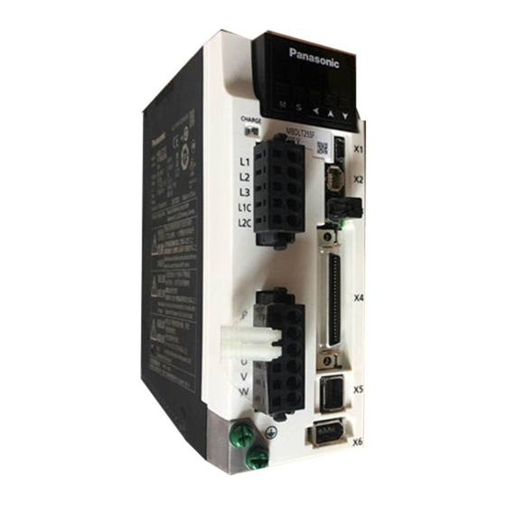
Panasonic MINAS A6 Multi Series Technical Reference
Ac servo driver
Hide thumbs
Also See for MINAS A6 Multi Series:
- Operating instructions manual (560 pages) ,
- Reference specifications (70 pages) ,
- Quick start manual (34 pages)
Advertisement
Quick Links
TECHNICAL REFERENCE
Industrial Device Solution Business Unit, Industrial Device Business Division,
Industrial Solutions Company, Panasonic Corporation
R1.7
– Functional Specification –
MODEL
Product Name
: AC Servo Driver
Product No.
: MINAS A6 Multi series
(EtherCAT communication/rotation type)
7-1-1 Morofuku, Daito-City, Osaka 574-0044, Japan
Phone
Fax : +81-72-870-3151
No. SX-DSV03455
Issued on
Jun. 16, 2020
Revised on
: +81-72-871-1212
Advertisement

Related Manuals for Panasonic MINAS A6 Multi Series


Summary of Contents for Panasonic MINAS A6 Multi Series
- Page 1 TECHNICAL REFERENCE – Functional Specification – MODEL Product Name : AC Servo Driver Product No. : MINAS A6 Multi series (EtherCAT communication/rotation type) Issued on Jun. 16, 2020 Revised on Industrial Device Solution Business Unit, Industrial Device Business Division, Industrial Solutions Company, Panasonic Corporation...
- Page 2 Translation is provided unofficially only for the sake of convenience of utilizing the original Japanese specification as a measure of reference. It is not officially reviewed. Industrial Device Solution Business Unit, Panasonic Corporation is not liable for any disadvantages caused by utilizing only English specification.
- Page 3 Revisions Date Page Rev. Description Signed Jun. 16, 2020 NEWLY ISSUED Note: The page number (Page) is the current page number at the time of revision.
- Page 4 Table of contents Table of contents 1. Introduction ..................1-1 Introduction ....................... 1-2 Basic specification ....................1-6 Function (Position control) ..................1-7 Function (Velocity control) ..................1-8 Function (Torque control) ..................1-9 Function (Full-closed control) .................. 1-10 Function (Common) ....................1-11 Differences from MINAS A6B series ...............
- Page 5 Table of contents 7-segment LED display ..................... 3-7 3.5.1 Station alias display mode .................... 3-8 3.5.2 Driver information display mode ..................3-8 3.5.3 Safety information display mode ................. 3-10 4. Basic Functions ................. 4-1 Rotational direction setup..................4-2 Position control ......................4-3 4.2.1 Process of command pulse input ..................
- Page 6 Table of contents 5.2.2 Block diagram of velocity control mode ..............5-28 5.2.3 Block diagram of torque control mode ................ 5-29 5.2.4 Block diagram of full-closed control mode ..............5-30 5.2.5 Gain switching function ....................5-31 5.2.6 Notch filter ........................5-36 5.2.7 Damping control ......................
- Page 7 Table of contents Retracting operation function (Not supported) ............6-26 6.10 Backlash correction function (Not supported) ............6-27 7. Protective Functions ................. 7-1 List of protective function ..................7-2 Details of protective function ..................7-6 7.2.1 Overload protection time characteristics ..............7-28 Warning function .....................
- Page 8 Table of contents 8.7.2 Safety fatal error status ....................8-17 8.7.3 EtherCAT object to check the safety status ..............8-17 Alarm clearing for safety monitoring ................ 8-19 Safety precautions ....................8-20 9. List of Parameters ................9-1 List of parameters ..................... 9-2 9.1.1 Class 0: Basic setting ....................
- Page 9 Table of contents 11.4.1 Basic block diagram ..................... 11-8 11.4.2 Regenerative control function ..................11-9 11.4.3 Main power off detection function ................11-9 11.5 Protective functions ....................11-10 11.5.1 List of protective functions ..................11-10 11.5.2 Details of protective functions ................... 11-11 11.5.3 Warning functions......................
- Page 10 Table of contents (Blank page)
- Page 11 Introduction...
- Page 12 This document describes the functions of the servo drive system MINAS A6 Multi series. The MINAS A6 Multi series consists of one power supply module (PSM) and up to 20 driver modules (DM) up to the maximum number of connections.
- Page 13 1.1Introduction MINAS A6 Multi series Functional comparison In this software version, the functions of "✖" are not supported in the table below. The description regarding these functions in the body text may be subject to change without prior notice at handling, hereafter.
- Page 14 Introduction MINAS A6BF Function MINAS A6 Multi (Multi-function type) External scale position information monitor function under ✔ ✖ semi-closed control ✔ ✔ Slow stop function ✔ ✔ Deterioration diagnosis warning function ✔ ✔ Position comparison output function ✔ ✖ SM2(synchronous with SM2 event) ✔...
- Page 15 The MINAS A6 Multi series may not be fully compatible with the A6B series. See the "REFERENCE SPECIFICATIONS Power supply module section (SX-DSV03452)" and "REFERENCE SPECIFICATIONS Driver module section (SX-DSV03454)"...
- Page 16 Introduction 1.2 Basic specification Item Contents Control method IGBT PWM sinusoidal wave drive Control mode Semi-closed control Modes of operation Position control Profile position mode Cyclic synchronous position mode Homing mode Velocity control Profile velocity mode Cyclic synchronous velocity mode Torque control Torque profile mode Cyclic synchronous torque mode...
- Page 17 1.3Function (Position control) 1.3 Function (Position control) Item Contents Positive/negative direction over-travel inhibition, External latch signal, Near home Control input position, etc. Control output Positioning completion etc. Input mode EtherCAT command Position command input Smoothing Filter Primary delay filter or FIR type filter is adaptable to the command input Damping control Available (Up to 3 frequency settings can be used simultaneously.) Model-type damping filter...
- Page 18 Introduction 1.4 Function (Velocity control) Item Contents Control input Positive/negative direction over-travel inhibition, External latch signal, etc. Control output At speed etc. Input mode EtherCAT command Velocity command input Soft start/stop 0 to 10 [s] / 1000 [r/min]. Acceleration and deceleration can be set separately. function S-curve acceleration/deceleration is available.
- Page 19 1.5Function (Torque control) 1.5 Function (Torque control) Item Contents Control input Positive/negative direction over-travel inhibition, External latch signal, etc. Control output At-speed etc. Torque command input Input mode EtherCAT command Speed limit Speed limit value can be Switched by EtherCAT command. function Damping control Not available...
- Page 20 Introduction 1.6 Function (Full-closed control) Item Contents Positive/negative direction over-travel inhibition, External latch signal, Near home Control input position, etc. Control output Positioning completion etc. Input mode EtherCAT command Position command input Smoothing Filter Primary delay filter or FIR type filter is adaptable to the command input 1/40 to 125200 times Although the ratio of encoder pulse (numerator) and external scale pulse External scale ratio...
- Page 21 1.7Function (Common) 1.7 Function (Common) Item Contents Electronic gear ratio Applicable scaling ratio: 1/1000–8000 The electronic gear ratio is limited by the combination of communication cycle, PDO size, and electronic gear ratio. For details, refer to "TECHNICAL REFERENCE EtherCAT Communication Specification (SX-DSV03456)". Auto-tuning The load inertia is identified in real time by the driving state of the motor operating according to the command given by the controller or setup support software...
- Page 22 Introduction 1.8 Differences from MINAS A6B series The MINAS A6 Multi series has the following specification differences compared to our MINAS-A6B series. Please contact us for specifications other than the following. SX-DSV03455 : TECHNICAL REFERENCE Functional Specification Section function...
- Page 23 1.8Differences from MINAS A6B series Section function content MINAS A6B MINAS A6 Multi 6.3.3 Sequence at main Availability Available Move to Power Supply module. power OFF Refer to section "11 Power Supply Module". Position comparison interface 3 photo-couppler output 2 photo-couppler output (SO1/SO2) output function (SO1/SO2/SO3) 2 line-driver output (OCMP1/OCMP2)
- Page 24 Introduction Section function content MINAS A6B MINAS A6 Multi List of parameters multi axis support Not available Available. Pr0.20 Pr4.00 to Pr4.07 Pr4.10 to Pr4.11 Pr5.88 to Pr5.90 Pr7.00 Pr7.116 to Pr7.118 Pulse regeneration Available Not available function Pr0.11, Pr0.12, Pr5.03, Pr5.33, Pr6.22 regenerative function Available...
- Page 25 1.8Differences from MINAS A6B series Section function content MINAS A6B MINAS A6 Multi 11.5 Protective functions Moved from driver Err18.0 PSM Err.07 module Err18.1 PSM Err.08 New addition to PSM Not available (Anomaly monitoring) PSM Err.05 PSM Err.06 PSM Err.09 PSM Err.10 PSM Err.14 (Inter-module communication)
- Page 26 Introduction (Blank page) 1-16...
- Page 27 Interface Specifications...
- Page 28 Interface Specifications 2.1 I/O connector input signal EtherCAT Connector Related control mode communications pin No. Signal name Symbol Contents Full- monitor (Note 2) Position Velocity Torque command close (Note 3) (Note 4) Input signal source SI-COM Connect to the positive or negative terminal of the external DC source (12–24 V).
- Page 29 2.1I/O connector input signal EtherCAT Connector Related control mode communications pin No. Signal name Symbol Contents Full- monitor (Note 2) Position Velocity Torque command close (Note 3) (Note 4) These signals are used for External latch input EXT1 ✔ ✔...
- Page 30 Interface Specifications 2.2 I/O connector output signal EtherCAT Connector Related control mode communications Signal name Symbol Contents pin No. Full- monitor Position Velocity Torque command (Note 2) close (Note 3) This signal shows that the driver is in Servo-Alarm output ALM [Axis A] alarm status.
- Page 31 2.2I/O connector output signal EtherCAT Connector Related control mode communications Signal name Symbol Contents pin No. Full- monitor Position Velocity Torque command (Note 2) close (Note 3) Outputs the zero-speed detection Zero-speed detection output signal. ✔ ✔ ✔ ✔ ✔...
- Page 32 Interface Specifications EtherCAT Connector Related control mode communications Signal name Symbol Contents pin No. Full- monitor Position Velocity Torque command (Note 2) close (Note 3) Servo on status SRV-ST Turns on the output transistor during ✔ ✔ ✔ ✔ ✔ output servo on.
- Page 33 2.2I/O connector output signal (Note 7) The general-purpose output 1 (EX-OUT1) can be replaced with the contactor output (MC-OUT) of the power supply module only for the Axis A of the driver module with the inter-module communication node address set to 1. In addition, the following parameter settings are required: <Relevant parameters>...
-
Page 34: For Manufacturer's Use
Interface Specifications 2.3 I/O connector other signal 2.3.1 Position comparison output signal EtherCAT Connector Related control mode communications Signal name Symbol Contents pin No. Full- monitor Position Velocity Torque command (Note 1) close (Note 2) The position compare output ✔... - Page 35 2.4I/O signal allocation function 2.4 I/O signal allocation function Default I/O signal allocation can be changed. 2.4.1 Input signal allocation Desired input signal can be allocated to any input pin of I/O connector. The logic can be changed. Some allocation limit is applied to specific signals. Refer to "2.4.1.2 Reallocation of input signal”. 2.4.1.1 Using with the default setting The table below shows default signal allocation.
- Page 36 Interface Specifications 2.4.1.2 Reallocation of input signal To change the allocation of input signal, change the following parameters. Relevant parameters Latch Parameter Class No. Attribute Unit Range Function correction name function SI1 input -2147483648 Assign functions to SI1 inputs. selection These parameters are presented in hexadecimals.
- Page 37 2.4I/O signal allocation function Latch Parameter correction Class No. Attribute Unit Range Function name function SI2 input -2147483648 Assign functions to SI2 inputs. selection Setup procedure is the same as described for Pr 2147483647 4.00. Axis B This pin has a latch correction function for Axis B. SI3 input -2147483648 Assign functions to SI3 inputs.
- Page 38 Interface Specifications Cautions for input signal assignment Do not setup to a value other than that specified in the table. The same signal can’t be assigned to multiple pins. Otherwise, duplicated assignment will cause Err 33.0 "Input multiple assignment error 1 protection" or Err 33.1 "Input multiple assignment error 2 protection". ...
- Page 39 2.4I/O signal allocation function Default setup Example of setup change Axis Selection Axis Selection Applicable parameter ( ): decimal ( ): decimal /Signal /Signal name notation notation / Logic / Logic Axis B Axis B 20222222h 20222222h Pr 4.00 /HOME /HOME (539107874) (539107874)
- Page 40 Interface Specifications Connections to use edge of the sensor signal as home position Axis A Axis B The over-travel inhibit input (POT, NOT) and forced alarm input (E-STOP) should normally be set to b-contact, which stops when wire is broken. If a-contact is specified, be sure that there is no safety hazard.
- Page 41 2.4I/O signal allocation function Default setup Applicable Default setting Pin name parameter ( ): decimal notation Axis Selection (Note 1) Signal 00010101h Pr 4.10 Axis A (65793) 20010101h Pr 4.11 Axis B (536936705) (Note 1) Axis selection sets which axis's output status is actually output. Axis A: Axis A output state is output.
- Page 42 Interface Specifications 2.4.2.2 Reallocation of input signal To change the allocation of output signal, change the following parameters. Relevant parameters Parameter Class No. Attribute Unit Range Function name SO1 output -2147483648 Assign functions to SO1 outputs. selection These parameters are presented in hexadecimals. 2147483647 Hexadecimal presentation is followed by a specific control mode designation.
- Page 43 2.4I/O signal allocation function Output function number table Title Symbol Setup value: a-contact Invalid Alarm output Servo-Ready output S-RDY External brake release signal BRK-OFF Positioning complete output At-velocity output AT-SPEED Torque in-limit signal output Zero-speed detection output signal Speed matching output V-COIN Warning output1 WARN1...
- Page 44 Interface Specifications 2.5 Mechanical brake output The mechanical brake release signal selected in Pr4.59 "Mechanical brake signal setting" is output from the mechanical brake output (BRK+/BRK-) of the driver module. Relevant parameters Parameter Class No. Attribute Unit Range Function name Mechanical 0 to 2...
- Page 45 2.5Mechanical brake output If the mechanical brake is operated while the servo motor is rotating, the mechanical brake may become abnormally worn or damaged and result in equipment failure. Releasing the brake on the vertical axis may cause the equipment to fall due to its own weight.
- Page 46 Interface Specifications (Blank page) 2-20...
- Page 47 Front Panel Specifications...
- Page 48 Front Panel Specifications 3.1 Front panel configuration Front panel cover opened Front panel cover closed...
- Page 49 3.2Node address setup in Inter-module communication 3.2 Node address setup in Inter-module communication In MINAS A6 Multi, driver modules up to maximum number of connections are connected to one power supply module, and inter-module communication is used to exchange information between these modules. For maximum number of connections, refer to "REFERENCE SPECIFICATIONS Power supply module section (SX-DSV03452)".
-
Page 50: For Manufacturer's Use
Front Panel Specifications 3.3 EtherCAT Station alias EtherCAT Station alias can be set up by the following three methods. Reading the value of SII from Configured Station Alias Reading the value of 0004h(Configured Station Alias) in the SII from 0012h(Configured Station Alias) of ESC register. - Page 51 3.4EtherCAT Indicators 3.4 EtherCAT Indicators MINAS A6 Multi series has 4 types of EtherCAT indicators (LED). There are 4 patterns of LED indication in addition to "ON" and "OFF". RUN RUN indicator will show the status of ESM(EtherCAT State Machine).
- Page 52 Front Panel Specifications L/A IN, L/A OUT L/A IN, L/A OUT indicator will show the LINK status and operation status of Each port’s physical layer. Indication is lighted in green. Content LINK not established Flickering LINK established. There are data transmission and reception. LINK established.
- Page 53 3.57-segment LED display 3.5 7-segment LED display The 7-segment LED on the front panel has 3 information display modes.
- Page 54 Front Panel Specifications 3.5.1 Station alias display mode When the control power is turned on, the station alias value set in the rotary switch or SII area (0004h) is displayed. After that, it automatically shifts to the driver information display mode. ...
- Page 55 3.57-segment LED display Pr 7.00 Information on display Remarks Axis A Axis B When an incremental external scale is used in the full closed control, the Z phase counter value read from the external scale is displayed as 0 to F[hex]. When the incremental external scale is used in full closed control or in semi-closed control with the external scale position information monitor function enabled, displays the value of Z phase counter read from external scale: 0 F hex.
- Page 56 Front Panel Specifications 3.5.3 Safety information display mode By pressing and holding the mode switch button for 3 seconds, you can switch between the driver information display mode and the safety information display mode. In the safety information display mode, various information on the safety part of the driver module is displayed.
- Page 57 Basic Functions...
- Page 58 Polarity (Rotational direction) can be set up to position command / velocity command / torque command, and each offset. In the MINAS A6 Multi series, the rotational direction cannot be set by Pr0.00 (Rotational direction setting), but it can be set by the object 607Eh (Polarity) specified to CoE (CiA402).
- Page 59 4.2Position control 4.2 Position control The driver module performs position control following the EtherCAT communication object position command input from the host controller. Below describes the basic settings necessary for position control. The control mode is switched forcibly inside the driver module depending on its operating status irrespective of the command from the host controller.
- Page 60 By using this function, the number of revolutions and travel of the motor per command can be set to the desired value. In MINAS A6 Multi series, a setup of an electronic gear ratio with a parameter Pr0.08(Number of command pulses per motor revolution), Pr0.09(Numerator of electronic gear) and Pr0.10(Denominator of...
- Page 61 4.2Position control The unit of the movement amount setting of the test run function by the setup support tool PANATERM for Multi is [command unit]. Communication cycle setup at 125 µs or 250 μs is supported only if the electronic gear ratio is 1:1.
- Page 62 Basic Functions Electronic gear setting example Under semi-closed control, When setting the electronic gear ratio of axis A by setting the number of command pulses per motor revolution 608Fh-01h (Encoder increments) is set automatically from the connected encoder resolution. By setting 608Fh-02h (Motor revolutions), 6091h-01h (Motor shaft revolutions), 6091h-02h (Driving shaft revolutions) and 6092h-02h (Driving shaft revolutions) to 1 (shipment condition), it is possible to set 6092h-01h (Feed) as the "number of command pulses per motor revolution".
- Page 63 When the PANATERM for Multi connect by the EoE communication, it can not be write objects using the object editor. For the MINAS A6 Multi series, the setting values by using the object editor are reflected to actual objects,and setting of electronic gear ratio is reflect to actual behavor at following timing same as previously via EtherCAT: ...
- Page 64 Basic Functions 4.2.3 Positional command filtering function To smooth the positional command processed by the electronic gear, set the command filter. Relevant parameters Class No. Attribute Title Range Unit Function Positional 0 to 10000 0.1 ms Set up the time constant of the 1st delay filter in response to the positional command.
- Page 65 4.2Position control Pr2.23 Positional command FIR filter When a square wave command of target speed Vc is applied, set up the Vc arrival time as shown in the figure below. *1 The actual average travel time (setup value x 0.1 ms) has the maximum absolute error of 0.2 ms for a time constant below 10 ms and the maximum relative error of 1.6% for a time constant 10 ms or more.
- Page 66 Basic Functions 4.2.4 Positioning complete output (INP/INP2) function The completion of positioning can be verified by the positioning complete output (INP) or the positioning complete output 2 (INP2). When the absolute value of the positional deviation counter at the position control is equal to or below the positioning complete range by the parameter, the output is ON.
- Page 67 4.2Position control Relevant parameters Class No. Attribute Title Range Unit Function Positioning 0 to Command Set the threshold of positional deviation with respect to the 2097152 unit output of positioning complete signal (INP). complete (In-position) range The unit of shipment setting is [Command unit], but it can be changed to [Encoder unit] or [External scale unit] by Pr5.20(Position setup unit select).In this case, the unit of Pr0.14 is changed too, please attention.
- Page 68 Basic Functions Class No. Attribute Title Range Unit Function Set the threshold of positional deviation with respect to the output of positioning complete (INP) signal. The INP2 turns ON whenever the positional deviation is lower than the value set up in this parameter, without being affected by Pr 4.32 Positioning complete output setup.
- Page 69 4.3Velocity control 4.3 Velocity control The driver module performs speed control following the EtherCAT communication object speed command input from the host controller. Below describes the basic settings necessary for speed control. As the speed control mode, there is a Profile velocity control(pv) and Cyclic synchronous velocity control(csv).
- Page 70 Basic Functions 4.3.1 Attained speed output (AT-SPEED) The AT-SPEED signal is output as the motor reaches the speed set to Pr 4.36 "Attained speed". Relevant parameters Class No. Attribute Title Range Unit Function At-speed 10 to 20000 r/min Set the detection timing of the speed arrival output (AT-SPEED).
- Page 71 4.3Velocity control 4.3.3 Velocity command acceleration/deceleration setting function This function controls the velocity by adding acceleration or deceleration command in the driver to the input velocity command. Using this function, you can use the soft start when inputting stepwise velocity command or when using internal velocity setup.
- Page 72 Basic Functions Pr 3.14 “Sigmoid acceleration/deceleration time setup” According to Pr 3.12 "Acceleration time setup" and Pr 3.13 "Deceleration time setup", set up sigmoid time with time width centering the inflection point of acceleration/deceleration. 4-16...
- Page 73 4.4Torque control 4.4 Torque control Torque control is performed based on the torque command object of the EtherCAT communication which is input from the host controller. This describe the basic configuration when using the torque control. Torque control is required speed limit command in addition to the torque command.
- Page 74 Basic Functions 4.4.1 Speed limit function The speed limit is one of protective functions used during torque control. This function regulates the motor speed so that it does not exceed the speed limit while the torque is controlled. While the speed limit is used to control the motor, the torque command applied to the motor is not directly proportional to the torque command from host controller.The torque command applied to the motor becomes the torque that the speed-controlled so that the motor speed becomes the speed limit value.
- Page 75 4.5Full-closed control 4.5 Full-closed control Full-closed control is where the position of the unit being controlled is controlled by direct feedback of the detected position using an externally located scale (external scale). This allows, for example, control that is not affected by ball screw errors or position variation from temperature.
- Page 76 Basic Functions 4.5.1 Selection of external scale type This section describes the selection of external scale type to be used and sets the direction. Relevant parameters Class No. Attribute Title Range Unit Function External scale 0 to 6 Selects the type of external scale.. selection 0: A, B phase output type 1: Serial communication type (Incremental specification)
- Page 77 4.5Full-closed control (Note 2) For the direction of external scale connection, make sure to connect so that the scale counting direction becomes as the count-up when the motor axis is rotated to the CCW direction, and as the count-down when the motor shaft is rotated to the CW direction. If the above mentioned directions are not possible depending on the installation conditions and others, the scale counting direction can be inverted using Pr3.26 "Reversal of direction of external scale".
- Page 78 Basic Functions 4.5.3 Setting of hybrid deviation excess The difference between the motor (encoder) position and load (external scale) position is detected, and when the difference exceeds Pr3.28 "Hybrid deviation excess setup", the hybrid deviation excess error protection is activated. The hybrid deviation excess occurs mainly when there is an external scale error, external scale connection fault, and motor-load connection looseness.
- Page 79 4.5Full-closed control 4.5.4 Full-closed control function (Rotary scale) (Not supported) MINAS A6 Multi does not support pulse regeneration function. 4-23...
- Page 80 Basic Functions 4.6 Setting regenerative resistor This function has been moved to the power supply module. Refer to section "11.4.2 Regenerative control function" 4-24...
- Page 81 4.7Absolute setup 4.7 Absolute setup 4.7.1 Absolute encoder When using the motor with absolute encoder, you can compose an absolute system, which does not require executing a homing operation at power-ON. For that, it is necessary to set Pr0.15 (Absolute encoder setup) to other than "1"...
- Page 82 Basic Functions Structure of absolute system Absolute system configuration using EtherCAT communication interface (Example: with driver module 2-axes connection) In the EtherCAT communication response (driver to host controller), the absolute data is transferred to the host controller as the current position data. *1 When connecting the battery, connect it to the junction connector on either the connector X9A/X9B side or the encoder side.
- Page 83 4.7Absolute setup Battery refreshment of the absolute encoder with battery If batteries (lithium-thionyl chloride battery) are not discharged for a long time, including long storage, battery alarm may occur due to the phenomenon of transient voltage drop at the next discharge. In order to prevent this, you can perform battery discharge treatment (refreshment).
- Page 84 Basic Functions 4.8 External scale position information monitor function (Not supported) MINAS A6 Multi does not support external scale position information monitor function under semi-closed control. 4-28...
- Page 85 Auto Tuning Functions...
- Page 86 Auto Tuning Functions 5.1 Automatic adjusting function The figure below shows outline of automatic adjusting function of MINAS A6 Multi series. Real-time auto tuning Estimates the load characteristics based on the motor velocity and torque command, and automatically sets up the basic gain related to position and velocity control, based on estimated inertia. Also estimates the friction torque at the same time and adds the estimated value to the torque command to shorten positioning settling time.
- Page 87 5.1Automatic adjusting function Caution After the power is turned on, estimate value following may become quicker regardless of Pr6.31 "Real time auto tuning estimation speed" until operation data effective for the estimation of load characteristics is sufficiently accumulated. When real-time auto-gain tuning is effective, an estimate value may become abnormal due to disturbance. If you want to obtain stable operation from when the power is turned on, it is recommended to disable the real-time auto-gain tuning.
- Page 88 Auto Tuning Functions Class No. Attribute Title Range Unit Function Real-time 0 to 31 You can set up the response while the real-time auto-gain tuning auto-tuning is valid. Higher the setup value, higher the velocity response and machine stiffness servo stiffness will be obtained. However, when increasing the setup value, check the resulting operation to avoid oscillation or vibration.
- Page 89 5.1Automatic adjusting function Content Description Stiffness Setup Enable/disable the basic gain setup to be made according to Pr0.03 "Real-time auto-tuning machine stiffness setup". (Note 5) Setup value Description Disable Enable Fixed parameter setup Enable/disable the change of parameter that is normally set at a fixed value. (Note 5) Setup value Description Use current setup...
- Page 90 Auto Tuning Functions Parameters changed by real-time auto-gain tuning The Real-time auto tuning function updates the following parameters according to Pr 0.02 "Real-time auto tuning setup" and Pr 6.32 "Real time auto tuning custom setup" and by using the load characteristic estimate values.
- Page 91 5.1Automatic adjusting function The Real-time auto tuning function sets the following parameters as the gain is switched. Relevant parameters Class No. Attribute Title Range Unit Function 2nd gain setup 0 to 1 Sets to 1 if the current setting is not maintained Mode of position 0 to 10 Sets to 10 to enable the gain switching.
- Page 92 Auto Tuning Functions How to use When Pr 0.02 (Setup of real-time auto-gain tuning mode) is set to a value other than 0, control parameter is automatically set according to Pr0.03 "Real-time auto tuning machine stiffness setup". When the servo is ON, enter operation command after about 100ms. When the load characteristic is correctly estimated, Pr 0.04 Inertia ratio is updated.
- Page 93 5.1Automatic adjusting function Basic gain parameter setup table For load fluctuation 1st gain 2nd gain suppression function Stiffness Pr 1.07 Pr 1.00 Pr 1.01 Pr 1.02 Pr 1.04 Pr 1.05 Pr 1.06 Pr 1.09 Pr 6.24 (Note 1) Velocity loop Velocity loop Load fluctuation Position...
- Page 94 Auto Tuning Functions 5.1.2 Adaptive filter This function estimates the resonance frequency from the vibrating component which appears on the motor velocity, and removes the resonance component from the torque command with adaptive filter, thus reduces the resonance vibration. Applicable range This function works under the following condition.
- Page 95 5.1Automatic adjusting function The adaptive filter automatically sets up the following parameters. Relevant parameters Class No. Attribute Title Range Unit Function 3rd notch frequency 50 to Notch frequency is automatically set to the 1st resonance 5000 frequency estimated by the adaptive filter. In no resonance point is found, the frequency is set to 5000.
- Page 96 Auto Tuning Functions 5.1.3 Real-time auto tuning (Two-degree-of-freedom control mode standard type) The 2 degrees of freedom control mode has two types: standard type and synchronization type. Standard type This is a standard mode. Use this mode normally. Synchronization type Use this mode for locus control of multiple axes of an articulated robot, etc.
- Page 97 5.1Automatic adjusting function Parameters controlling operation of real-time auto tuning Configure the Real-time auto tuning operation by setting the following parameters. Relevant parameters Class No. Attribute Title Range Unit Function Real-time auto-gain 0 to 6 Specifies the operation mode of Real-time auto tuning. tuning setup Setup Mode...
- Page 98 Auto Tuning Functions Parameter changed by real-time auto tuning The Real-time auto tuning function updates the following parameters using load characteristic values, in accordance with Pr0.02 "Real-time auto-gain tuning setup." Relevant parameters Class No. Attribute Title Range Unit Function Inertia ratio 0 to Updates this parameter when the Real-time auto tuning...
- Page 99 5.1Automatic adjusting function Real-time auto-tuning function sets the following parameters to the fixed value. Relevant parameters Class No. Attribute Title Range Unit Function 1st filter of velocity 0 to 5 detection When fixed parameter setup is valid (Pr0.02=1 to 4), set the parameter to 0.
- Page 100 Auto Tuning Functions Class No. Attribute Title Range Unit Function Position 3rd gain valid 0 to 0.1 ms For the standard response mode or high response mode 1 time 10000 (Pr0.02=1, 2), set the parameter to 0 (invalid). For high response mode 2 or 3 (Pr0.02=3,4), set the parameter to "Pr2.22 x 20".
- Page 101 5.1Automatic adjusting function Other cautions Strange noises or vibrations may occur on the first action of turning immediately after startup or setting higher value of Pr0.03 "Real-time auto tuning machine stiffness setup" until estimation of load characteristic becomes stable. This is not a fault if the function becomes stable soon. If oscillation or continued generation of abnormal noise through three or more reciprocating movements often occurs, take the following steps.
- Page 102 Auto Tuning Functions Basic gain parameter setup table For load fluctuation 1st gain / 2nd gain Command response Tuning filter suppression function Stiffness Pr 1.00 Pr 1.01 Pr 1.02 Pr 1.04 Pr 2.22 Pr 6.48 (Note 1) Pr 6.24 Pr 1.05 Pr 1.06 Pr 1.07 Pr 1.09...
- Page 103 5.1Automatic adjusting function 5.1.4 Real-time auto tuning (Two-degree-of-freedom control mode synchronization type) The 2 degrees of freedom control mode has two types: standard type and synchronization type. Standard type This is a standard mode. Use this mode normally. Synchronization type Use this mode for locus control of multiple axes of an articulated robot, etc.
- Page 104 Auto Tuning Functions Parameters controlling operation of Real-time auto tuning Configure the Real-time auto tuning operation by setting the following parameters. Relevant parameters Class No. Attribute Title Range Unit Function Real-time auto-gain 0 to 6 Specifies the operation mode of Real-time auto tuning. tuning setup Setup Mode...
- Page 105 5.1Automatic adjusting function Parameter changed by Real-time auto tuning The Real-time auto tuning function updates the following parameters according to Pr0.02 "Real-time auto-tuning setup" by using the load characteristic estimate value. Relevant parameters Class No. Attribute Title Range Unit Function Inertia ratio 0 to...
- Page 106 Auto Tuning Functions Real-time auto tuning function sets the following parameters to the fixed value. Relevant parameters Class No. Attribute Title Range Unit Function 1st filter of velocity 0 to 5 In the case of the synchronization mode, synchronous detection friction compensation mode, stiffness setup mode, or load change support mode (Pr0.02=1 to 3, 6), set the parameter...
- Page 107 5.1Automatic adjusting function Class No. Attribute Title Range Unit Function Delay time of velocity 0 to 0.1 ms Sets to 0 if the case of the synchronization mode, control switching 10000 synchronous friction compensation mode, stiffness setup mode, or load change support mode (Pr0.02=1 to 3, 6). Level of velocity 0 to Sets to 0 if the case of the synchronization mode,...
- Page 108 Auto Tuning Functions In case Pr 0.02 "Real-time auto-gain tuning setup" = 6 (load fluctuation response mode), the setting will be changed to the following. Relevant parameters Class No. Attribute Title Range Unit Function Function expansion -32768 to Load fluctuation suppression function always become setup 32767 enabled (bit1 = 1, bit2=1, bit14=1)
- Page 109 5.1Automatic adjusting function The control gain is updated when the motor is stopped. Therefore, if the motor is not stopped because gain is excessively low or commands are given continually in one direction, the change in the set value for Pr0.03 "Real-time auto tuning machine stiffness setup"...
- Page 110 Auto Tuning Functions 5.2 Manual adjusting function MINAS A6 Multi series features the automatic gain tuning function, however, there might be some cases where this automatic gain tuning cannot be adjusted properly depending on the limitation on load conditions. Or you might need to readjust the tuning to obtain the optimum response or stability corresponding to each load.
- Page 111 5.2Manual adjusting function 5.2.1 Block diagram of position control mode Position control of MINAS A6 Multi series, there are three modes. Profile position mode (pp) Cyclic synchronous position mode (csp) Homing mode (hm) Interpolated position mode (ip) is not supported.
- Page 112 Auto Tuning Functions 5.2.2 Block diagram of velocity control mode Velocity control of MINAS A6 Multi series, there are two modes. Profile velocity mode (pv) Cyclic synchronous velocity mode (csv) Block diagram of velocity control *1 A slanting number shows (ex: 607Ah) the object number of EtherCAT.
- Page 113 5.2Manual adjusting function 5.2.3 Block diagram of torque control mode Telocity control of MINAS A6 Multi series, there are two modes. Profile torque mode (tq) Cyclic synchronous torque mode (cst) Block diagram of torque control *1 A slanting number shows (ex: 607Ah) the object number of EtherCAT.
- Page 114 Auto Tuning Functions 5.2.4 Block diagram of full-closed control mode Full-closed control of MINAS A6 Multi series, there are three modes. Profile position mode (pp) Cyclic synchronous position mode (csp) Homing mode (hm) Interpolated position mode (ip) is not supported.
-
Page 115: For Manufacturer's Use
5.2Manual adjusting function 5.2.5 Gain switching function By selecting appropriate gain based on internal data or external signal, the following effects can be obtained. Decrease the gain at the time of stoppage (servo lock) to reduce vibration. Increase the gain at the time of stoppage (setting) to shorten the settling time. ... -
Page 116: For Manufacturer's Use
Auto Tuning Functions Attribute Class No. Title Range Unit Function (Note 1) Mode of velocity 0 to 5 For velocity controlling: Set the condition to trigger gain control switching switching. Setup value Switching condition Fixed to 1st gain Fixed to 2nd gain For manufacturer’s use Torque command Velocity command variation is larger. -
Page 117: For Manufacturer's Use
5.2Manual adjusting function How to use Set the gain switching mode for the control mode to be used, and enable the gain switching function through Pr 1.14 2nd gain setup (set Pr 1.14 to 1). Switching mode Switching condition Gain switching condition (Pr1.15) Setup value Fixed to 1st gain... - Page 118 Auto Tuning Functions How to set Suppose the load travels from A to B position and the internal status of the drive changes as the figure below shows. Hereunder we explain how to set up the relevant parameters when you use the gain switching function.
- Page 119 5.2Manual adjusting function 2. Set up the switching level and Hysteresis depending on the switching conditions. 3. Set up the switching delay time. Set up the time delay for switching from 2nd gain to 1st gain. Switching conditions have to be established continuously during the switching delay time for the switching from the 2nd to the 1st.
- Page 120 By suppressing the resonance peak at the notch filter, higher gain can be obtained or the level of vibration can be lowered. Relevant parameters MINAS A6 Multi series feature 5 normal notch filters. You can adjust frequency and width and depth. Relevant parameters Class No. Attribute...
- Page 121 5.2Manual adjusting function Notch width and depth The width of the notch filter is the ratio of the width of –3 dB attenuation frequency band with respect to the notch frequency at its center when depth is 0, and the value is as shown in the table below. The notch filter depth indicates I/O ratio where the input at the center frequency is completely shut with setup value 0 but fully received with setup value 100.
- Page 122 Auto Tuning Functions 5.2.7 Damping control This function reduces the vibration at the top or on whole of the equipment by removing the vibration frequency components specified by the positional command. Up to 3 frequency settings, out of 4 settings in total, can be used simultaneously.
- Page 123 5.2Manual adjusting function Relevant parameters Set up damping control operation using the parameters shown below. Relevant parameters Class No. Attribute Title Range Unit Function Selection of 0 to 6 Among 4 filters select the filters to be used for damping control. damping filter ...
- Page 124 Auto Tuning Functions Class No. Attribute Title Range Unit Function 1st damping 0 to 3000 0.1 Hz You can set up the 1st damping frequency of the damping frequency control which suppresses vibration at the load edge. The driver measures vibration at load edge. Setup unit is 0.1 [Hz] The setup frequency is 0.5 to 300.0 [Hz].
- Page 125 5.2Manual adjusting function Attribute Class No. Title Range Unit Function (Note 1) 3rd damping depth 0 to 1000 - Defines the depth against the 3rd damping frequency. The depth becomes maximum if the setup value is 0. The larger the setup value, the smaller the depth. Although the damping effect increases as the depth becomes larger, the delay becomes large.
- Page 126 Auto Tuning Functions How to use Setup of damping frequency (1st: Pr 2.14, 2nd: Pr 2.16, 3rd: Pr 2.18, 4th: Pr 2.20) Measure the vibration frequency of the front edge of the machine. When you use such instrument as laser displacement meter, and can directly measure the load end vibration, read out the vibration frequency by 0.1 [Hz] from the measured waveform and enter it.
- Page 127 5.2Manual adjusting function 5.2.8 Model-type damping filter (Not supported) MINAS A6 Multi does not support model-type damping filter. 5-43...
- Page 128 The feed forward given through EtherCAT communication is added to the feed forward value (internally calculated according to the parameter setting). Relevant parameters For MINAS A6 Multi series, the velocity feed forward and torque feed forward can be used. Relevant parameters Class No.
- Page 129 5.2Manual adjusting function Usage example of velocity feed forward The velocity feed forward will become effective as the velocity feed forward gain is gradually increased with the velocity feed forward filter set at approx. 50 (0.5 ms). The positional deviation during operation at a constant velocity is reduced as shown in the equation below in proportion to the value of velocity feed forward gain.
- Page 130 Auto Tuning Functions If the control mode is changed from other than torque control mode to torque control mode while the motor is in operation, torque feed forward may be applied even if torque control mode. 5-46...
- Page 131 5.2Manual adjusting function Corresponding control mode In addition, each feedforward which can setup by EtherCAT communication corresponds to the following control mode. ip (Not supported) 60B1h/68B1h Valid Valid Valid Valid Valid Valid Invalid Invalid ✔ ✔ ✔ ✔ ✔ ✔ ✖...
- Page 132 Auto Tuning Functions 5.2.10 Load variation suppression function This function uses the disturbance torque determined by the disturbance observer to reduce effect of disturbance torque and vibration. This is effective when Real-time auto tuning cannot handle load variation sufficiently. Applicable range This function can be applicable only when the following conditions are satisfied.
- Page 133 5.2Manual adjusting function Attribute Class No. Title Range Unit Function (Note 1) Torque 0 to 5000 0.1 Hz Defines the filter frequency 1 against the velocity control output. compensation Torque compensation is enabled when the relation between Pr. frequency 1 6.74 "Torque compensation frequency 1"...
- Page 134 Auto Tuning Functions Load variation stabilization setting (There is load inertia variation, assumed an articulated robot, etc.) 1. Turn ON the control power in two-degree-of-freedom position control (synchronization type) (Pr. 0.01=0, Pr. 6.47 bit0=1 bit3=1). 2. Set the command response filter (Pr. 2.22) to 10ms. 3.
- Page 135 5.2Manual adjusting function 5.2.11 3rd gain switching function In addition to the normal gain switching function described on "5.2.5 Gain switching function", 3rd gain switching function can be set to increase the gain just before stopping. The higher gain shortens positioning adjusting time.
- Page 136 Auto Tuning Functions 5.2.12 Friction torque compensation To reduce effect of friction represented by mechanical system, 3 types of friction torque compensation can be applied: Offset load compensation that cancels constant offset torque The dynamic friction compensation that varies direction as the operating direction varies ...
- Page 137 5.2Manual adjusting function How to use The friction torque compensation will be added in response to the entered positional command direction as shown below. Pr 6.07 "Torque command additional value" reduces variations in positioning operation (performance is affected by direction of movement). These variations occur when constant offset torque resulting from weight on vertical axis is applied to the motor.
- Page 138 Auto Tuning Functions 5.2.13 Hybrid vibration damping function A function to suppress vibration arising from the twist amount between the motor and the load in the Full-closed control mode. This function enables high setting of gains. Applicable range This function is unable to be applied unless the following conditions are satisfied. Conditions in which hybrid vibration suppression functions are activated: ...
- Page 139 5.2Manual adjusting function 5.2.14 Two-stage torque filter In addition to usual 1st and 2nd torque filters (Pr1.04 and Pr1.09), another torque filter can be set. High-frequency vibration component can be suppressed by the use of the 2-stage torque filter. Applicable range This function can’t be applied unless the following conditions are satisfied.
- Page 140 Auto Tuning Functions 5.2.15 Quadrant projection suppression function Control configuration can be switched to suppress quadrant projection occurring during arc interpolation of 2 or more axes. To be used in conjunction with load fluctuation suppression function. Applicable range This function is unable to be applied unless the following conditions are satisfied. Conditions in which quadrant projection suppression function is triggered: ...
- Page 141 5.2Manual adjusting function How to use Adjust the load change inhibit function using the disturbance suppression setup by reference to Section "5.2.10 Load variation suppression function", and measure quadrant projection. Level is unsatisfactory, conduct further fine adjustment using quadrant projection suppression function. 1.
- Page 142 Auto Tuning Functions 5.2.16 Two-degree-of-freedom control mode (with position control) The two-degree-of-freedom control mode is an expanded function of the position control switching mode. Responsiveness is improved by making it possible to set the positional command response and servo stiffness independently. Either of the standard type or synchronization type of the two-degree-of-freedom control can be used.
- Page 143 5.2Manual adjusting function Class No. Attribute Title Range Unit Function Adjust filter 0 to 2000 0.1ms Set the time constant for the adjust filter. When the torque filter setting has been changed, set a value close to the real-time auto-tuning setting. ...
- Page 144 Auto Tuning Functions Two-degree-of-freedom control mode (with position control) The mode of 2 degrees of freedom control is configured as shown in the block diagram below. Two-degree-of-freedom control mode (with position control) block diagram *1 A slanting number shows (ex: 607Ah) the object number of EtherCAT. *2 A bold letter number shows (ex:1.00) a parameter number.
- Page 145 5.2Manual adjusting function 5.2.17 Two-degree-of-freedom control mode (with velocity control) The two-degree-of-freedom control mode is an extended function of velocity control mode to improve the responsiveness by making it possible to independently set the command response and servo rigidity. Only the standard type of two-degree-of-freedom control is available. Applicable range This function is unable to be applied unless the following conditions are satisfied.
- Page 146 Auto Tuning Functions Block diagram of the two-degrees-of-freedom control mode (with velocity control) Two-degree-of-freedom control mode (with velocity control) shall be as per the block diagram indicated below. Two-degree-of-freedom control mode (with velocity control) block diagram *1 A slanting number shows (ex: 607Ah) the object number of EtherCAT. *2 A bold letter number shows (ex:1.00) a parameter number.
- Page 147 5.2Manual adjusting function 5.2.18 Two-degree-of-freedom control mode (with full-closed control) The two degree-of-freedom control mode is an extended function of Full-closed control mode to improve the responsiveness by making it possible to independently set the command response and servo rigidity. Only the standard type of two-degree -of-freedom control is available.
- Page 148 Auto Tuning Functions Attribute Class No. Title Range Unit Function (Note 1) Adjust filter 0 to 2000 0.1 ms Set the time constant for the adjust filter. When the torque filter setting has been changed, set a value close to the real-time auto-tuning setting. ...
- Page 149 5.2Manual adjusting function Block diagram of the two-degrees-of-freedom control mode (with Full-closed control) Two-degree-of-freedom control mode (with Full-closed control) shall be as per the block diagram indicated below. Two-degree-of-freedom control mode (with full-closed control) block diagram *1 A slanting number shows (ex: 607Ah) the object number of EtherCAT. *2 A bold letter number shows (ex:1.00) a parameter number.
- Page 150 Auto Tuning Functions 5.2.19 Two-degree-of-freedom control mode (with torque control) Torque control is the same regardless of whether the 2-DOF control mode is enabled or disabled. For details, refer to "TECHNICAL REFERENCE EtherCAT Communication Specification (SX-DSV03456)". 5.2.20 High response current control High response current control is a function to improve the responsiveness of the current control part by changing Pr6.11 "Current response setup"...
- Page 151 Application Functions...
- Page 152 Application Functions 6.1 Torque limit switching function It is a function which changes a torque limit value by the direction of operation. Applicable range This function can be applicable only when the following conditions are satisfied. Conditions under which the Torque limit switching function is activated: ...
- Page 153 6.2Motor working range setup function 6.2 Motor working range setup function If the motor with respect to the position command input range exceeds the motor operating range that is set by Pr5.14"Motor working range setup", it can be alarm stop at the Err34.0 "motor movable range set protection"...
- Page 154 Application Functions Relevant parameters Relevant parameters Class No. Attribute Title Range Unit Function Motor working 0 to 1000 You can set up the movable range of the motor against range setup revolution the position command input range. When the motor movement exceeds the setup value, software limit protection will be triggered.
- Page 155 6.3Deceleration stop sequence 6.3 Deceleration stop sequence Sets how to decelerate and stop the motor if main power is shut down or an alarm occurs while PDS is Operation enabled state (servo-on state). Combine the deceleration function (option code) defined by CoE(CiA402) and the deceleration function on the servo (MINAS A6) side (dynamic brake stop, free-run stop, emergency stop).
- Page 156 Application Functions Contents Detail of deceleration stop on servo (MINAS A6) side (Pr5.04 = 0) Pr 5.04 Pr 5.05 During deceleration (Note 5) After stalling (Approx. 30 r/min or below) (Note 4) Stopping method Deviation Operation after stopping Deviation ...
- Page 157 6.3Deceleration stop sequence 6.3.2 Sequence at servo-off Operation sequence of the servo-off state is set by 605Ah/685Ah (Quick stop option code), 605Bh/685Bh (Shutdown option code) and 605Ch/685Ch (Disable operation option code). Deceleration function on the servo (MINAS A6) side is activated when these objects is zero. Deceleration function on the CoE (CiA402) side is activated when these objects is non-zero.
- Page 158 Application Functions 6.3.3 Sequence at main power OFF The operation sequence at the main power supply OFF is changed with combination, such as 6007h/6807h (Abort connection option code), Pr5.07 (main power off sequence), and PSM Pr.02 (main power off detection time).
- Page 159 Application Functions Contents Details of Pr 5.07 (Sequence at main power OFF) During deceleration (Note 4) After stalling (Approx. 30 r/min or below) Pr 5.07 Operation after stopping Stopping method Deviation Deviation Pr6.36 = 0 Pr6.36 = 1 Forcibly controls the position. (Note 1) ...
- Page 160 6.3Deceleration stop sequence 6.3.4 Sequence at alarm Set the operation sequence at the alarm with the exception of the communication related alarm (Err80.*, Err81.*, Err85.*, Err88.*). Communication related alarms (Err80.*, Err81.*, Err85.*, Err88.*) information, set by 605Eh/685Eh (Fault reaction option code).
- Page 161 Application Functions (Note 3) Action of A/B: When an alarm requiring emergency stop occurs, the action A is selected when the setup value in the table is set within the range 4 to 7, causing emergency stop of operation. When an alarm not requiring emergency stop occurs, it triggers dynamic braking (DB) specified by action B, or free-running.
- Page 162 6.3Deceleration stop sequence When an alarm requiring emergency stop occurs, normal operation (the normal torque limit is enabled) continues until an emergency stop is started. Therefore, if the command is interrupted during this period, the torque controlled with the normal torque limit may be output. To stop operation with the emergency stop torque limit when an alarm requiring emergency stop occurs, continue to send the normal position command for at least 4 ms from the alarm notification.
- Page 163 Application Functions 6.3.6 Fall prevention function in the event of alarms/servo-ON 6.3.6.1 Fall prevention function in the event of alarms If the alarm requiring emergency stop has occurred, falling of the robot arm is prevented by maintaining the energization to the motor until the external brake is actually operated after the brake release output (BRK-OFF) is turned OFF.
- Page 164 6.3Deceleration stop sequence 6.3.6.2 Fall prevention function in the event of servo-ON By using object 60B2h / 68B2h (Torque offset), the offset value is input to the torque filter when the servo is turned off, eliminating the delay in rising the torque command at the servo-on command input timing and preventing the device from falling.
- Page 165 Application Functions 6.3.7 Slow stop function When a drive prohibition input, servo-off, main power-off, or immediate-stop alarm is detected with immediate stop settings, the motor can be smoothly stopped by applying control while the servo is on. Applicable range This function cannot be applied unless the following conditions are satisfied. Condition for activation of slow stop function: ...
- Page 166 6.3Deceleration stop sequence Attribute Class No. Title Range Unit Function (Note 1) Emergency stop 0 to 1000 ms Sets the allowable time for stopping when alarm is triggered for time at alarm emergency stop. Exceeding this set value will trigger a forced alarm condition.
- Page 167 Application Functions Slow stop operation : S-shape deceleration S shape process at the time of slow stop operation can be made by setting Pr5.57. Refer to the following figure to set Pr5.57. * Velocity control command at the time of starting slow stop operation shall be calculated from the actual velocity. ...
- Page 168 6.4Torque saturation protection function 6.4 Torque saturation protection function If torque saturated has continued for a fixed period, an alarm can be activated. Relevant parameters Relevant parameters Class No. Attribute Title Range Unit Function Torque saturation 0 to 5000 ms Set the torque saturation error protection detection time.
- Page 169 Application Functions 6.5 Position comparison output function This function enables a general-purpose output or position comparison output terminal to output a pulse signal when the actual position passes the position set for the parameter. Specification Item Description Trigger output With the 2 axes combined, 2-outputs: Photocoupler (Open Collector) or 2-outputs: Line driver Logic Parameter settings (The polarity can be set for each output)
- Page 170 6.5Position comparison output function Relevant parameters Relevant parameters Class No. Attribute Title Range Unit Function SO1 output -2147483648 When using SO1 output as position compare output selection to 2147483647 (CMP-OUT), assign position compare output (CMP-OUT: 14h) to Pr4.10 for all control modes. A-axis position compare output : 1315860 (00141414h) B-axis position compare output : 538186772...
- Page 171 Application Functions Class No. Attribute Title Range Unit Function Position -2147483648 Set the output terminals corresponding to position comparison output to 2147483647 comparison values 1 to 8 by bit setup.Multiple position assignment setting comparison values can be set up on one output terminal.
- Page 172 6.5Position comparison output function Also when the position stops at the same position as the position comparison value, the pulse is output only once as with the case of passage. The position comparison output function sends outputs while automatically compensating, based on the previous motor speed, the errors caused by the time of delay of encoder serial communication, etc.
- Page 173 Application Functions 6.6 Single-turn absolute function This function uses the absolute encoder as an absolute system only for single-turn absolute position data without connecting the battery power. The movable range of the motor is limited by single-turn data of the absolute encoder. Applicable range This function operates under the following conditions.
- Page 174 6.6Single-turn absolute function Operation example The effective range of the single turn is as follows. CCW = Positive direction, electronic gear ratio = 1/1, 607Ch/687Ch(Home offset) = 0 CCW = Positive direction, electronic gear ratio = 1/2, 607Ch/687Ch(Home offset) = 0 ...
- Page 175 Application Functions Cautions on the motor position upon power-ON The motor working range is determined depending on the motor position upon power-ON. (Operation example with a 23 bit absolute encoder) (1) When the power-ON position is as shown in the figure below, the motor working range is the single-turn data range from the power-ON position.
- Page 176 6.7Infinitely rotation absolute function 6.7 Infinitely rotation absolute function This function allows you to set any upper limit value for absolute encoder multi-turn data. With this function, it is possible to determine the turn angle (position) of a turntable and such other applications, even in the case of continuous turn in one direction.
- Page 177 Application Functions Related object Data Index Name Description Units Range Access PDO EEPROM Index Type mode 607Ch Home After the homing position control Command -2147483648 RxPDO ALL offset mode (hm), position information is /687Ch set so that the detected index 2147483647 pulse position becomes equal to the value of this object.
- Page 178 6.7Infinitely rotation absolute function Operation example The operation is as follows in the case of the deceleration ratio (m=50, n=4) where the turntable makes 4 turns when the motor makes 50 turns. 1. Set Pr0.15=4 and Pr6.88=49, and write to EEPROM. 2.
- Page 179 Application Functions Absolute home position offset When using the infinite rotation absolute function, the absolute home position offset is as follows. CCW = Positive direction, electronic gear ratio = 1/1, Pr6.88 "Absolute encoder multi-turn data upper-limit value" = 2, 607Ch/687Ch(Home offset) = 10000 ...
- Page 180 6.8Deterioration diagnosis warning function 6.8 Deterioration diagnosis warning function This is a function to check the changes in motor and connected equipment characteristics to output deterioration diagnosis warning. Relevant parameters Relevant parameters Class No. Attribute Title Range Unit Function Deterioration diagnosis 0 to 10000 0.1 s...
- Page 181 Application Functions Class No. Attribute Title Range Unit Function Deterioration diagnosis -1000 to 1000 0.1% Sets the upper and lower limit values of torque command torque upper limit value average value when deterioration diagnosis warning is valid (Pr6.97 bit 1 = 1) and deterioration diagnosis Deterioration diagnosis velocity output (V-DIAG) is ON.
- Page 182 6.8Deterioration diagnosis warning function Deterioration diagnosis warning for constant velocity torque command average value Deterioration diagnosis velocity output (V-DIAG) is ON when the motor velocity is within the range of Pr4.35 "Speed coincidence range" of Pr5.75 "Deterioration diagnosis velocity setting". ...
- Page 183 Application Functions 6.9 Retracting operation function (Not supported) MINAS A6 Multi does not support retracting operation function. 6-26...
- Page 184 6.10Backlash correction function (Not supported) 6.10 Backlash correction function (Not supported) MINAS A6 Multi does not support retracting operation function. 6-27...
- Page 185 Protective Functions...
- Page 186 Protective Functions 7.1 List of protective function This driver module incorporates various protective functions. When a protective function is enabled, the driver module turns OFF the alarm signal (ALM) and displays the error number on 7-segment LED of the panel section at front surface. Alarms does not occur for axes that are disabled by Pr0.20 “Axis limit setting”.
- Page 187 7.1List of protective function Error No. Attribute EtherCAT communication Can be Emergency Alarm Common related Main Sub History cleared stop (Note 8) (Note 4)(Note 7) (Note 3) (Note 6) EEPROM parameter error protection EEPROM check code error protection ✔ Over-travel inhibit input protection 1 ✔...
- Page 188 Protective Functions Error No. Attribute EtherCAT communication Can be Emergency Alarm Common related Main Sub History cleared stop (Note 8) (Note 4)(Note 7) (Note 3) (Note 6) ✔ ✔ ✔ ✔ Synchronization cycle error protection ✔ ✔ ✔ ✔ Mailbox error protection ✔...
- Page 189 7.1List of protective function (Note 4) When clearable alarm other than EtherCAT communication-related error (Err80.*, Err81.*, Err85.*, Err88.*) is occurred, it will be able to clear the alarm in the following way. When an alarm clear input (A-CLR) is OFF, or while not assigning, the alarm clearance was performed from EtherCAT communication or PANATERM for Multi(USB communication, EoE communication).
- Page 190 Protective Functions 7.2 Details of protective function Error No. Protective function Causes Measures Main Control power supply The voltage of the bus (control power Measure the applied voltage of control undervoltage protection supply) of the driver module has dropped to power connector X11.
- Page 191 7.2Details of protective function Error No. Protective function Causes Measures Main (When bit 0 of Pr5.08 “L/V trip selection DC busundervoltage Measure the applied voltage of main power upon main power off” of the driver module, if protection connector X102. any axis of the driver module is servo-on, Check if the voltage is insufficient.
- Page 192 Protective Functions Error No. Protective function Causes Measures Main Over-heat protection The temperature of the radiator and power Check the operating temperature range of element of the driver module exceeded the the driver module. specified value. Ambient temperature has risen over Improve the ambient temperature and the specified temperature.
- Page 193 7.2Details of protective function Error No. Protective function Causes Measures Main Over-load protection In the driver module, the overload load Check if the torque (current) waveform is factor calculated from the torque command oscillating with large variations in the of each axis servo motor exceeded the vertical direction in EtherCAT specified value.
- Page 194 Protective Functions Error No. Protective function Causes Measures Main Mechanical brake circuit The power supply input voltage to the When not using the mechanical brake, set voltage error protection mechanical brake output circuit of the motor bit 0 (mechanical brake circuit voltage error protection function) of Pr5.90 “...
- Page 195 7.2Details of protective function Error No. Protective function Causes Measures Main Position deviation excess In the driver module, the position deviation Remove the cause of excessive position protection pulse of each axis exceeds the setting of Pr deviation. 0.14 “Position deviation excess setup”. Alternatively, the positional deviation excess determination threshold value is increased.
- Page 196 Protective Functions Error No. Protective function Causes Measures Main Check if multi-turn clear of absolute Absolute clear protection In the driver module, Multi-turn clear of absolute encoder of each axis was made encoder has been made through from PANATERM for Multi(USB PANATERM for Multi(USB communication, EoE communication).
- Page 197 7.2Details of protective function Error No. Protective function Causes Measures Main Safety function error A communication error with the safety part In case of the repeated occurrence, protection 3 was detected inside the driver module. because failure is possible, replace the driver module.
- Page 198 Protective Functions Error No. Protective function Causes Measures Main Software limit protection In the driver module, when a position Improves followability to the position command within the specified input range of command. each axis is given, the motor operates Alternatively, the motor movable range outside its working range specified in Pr setting range is expanded.
- Page 199 7.2Details of protective function Error No. Protective function Causes Measures Main Over-travel inhibit input In the driver module, when Pr 5.04 Check that there are not any errors in “over-travel inhibit input setup” = 0 for each protection 1 switches, wires or power supply which are axis, both positive and negative over-travel connected to positive direction/ negative inhibit inputs (POT/NOT) have been ON.
- Page 200 Protective Functions Error No. Protective function Causes Measures Main Absolute over-speed In the driver module, the following situation Prevent the motor from moving at high occurred when Pr0.15 “Absolute encoder error protection speed in the battery backup state. It was setting”...
- Page 201 7.2Details of protective function Error No. Protective function Causes Measures Main In the driver module, check the A-phase A-phase connection error In the driver module, A-phase connection in protection 2nd encoder for each axis (A/B/Z external connection of 2nd encoder for each axis scale) is defective, e.g.
- Page 202 Protective Functions Error No. Protective function Causes Measures Main The power supply module detected a Check that the power supply module Inter-modules communication timeout disconnection of Inter-modules communication cable is connected error protection communication or an error in received properly.
- Page 203 7.2Details of protective function Error No. Protective function Causes Measures Main Turn off power once, and turn on again. U-phase current detector In the driver module, each axis motor error protection U-phase current detection offset value has Even so, if an error indication appears and some error.
- Page 204 Protective Functions Error No. Protective function Causes Measures Main PLL error protection In the EtherCAT communication of the <In case of DC> driver module, in the ESM state is SafeOP Check setting of DC mode. or OP, phasing servo and communication ...
- Page 205 7.2Details of protective function Error No. Protective function Causes Measures Main Synchronization cycle In the EtherCAT communication of the Please set up a synchronous period error protection driver module, it is set to an unsupported correctly. synchronization cycle (SYNC0 cycle or an IRQ cycle).
- Page 206 Protective Functions Error No. Protective function Causes Measures Main DC error protection In the EtherCAT communication of the Check setting of DC mode. driver module, DC setting setup is incorrect. A value other than the following was set to bit 2-0 of 0981h (Activation) of the ESC register: bit 2-0 = 000b...
- Page 207 7.2Details of protective function Error No. Protective function Causes Measures Main Turn the power off once, then turn it on Synchronous In the EtherCAT communication of the establishment driver module, error occurred during again. initialization error initialization process of phasing ...
- Page 208 Protective Functions Error No. Protective function Causes Measures Main The capacity rise of power supply voltage. Main power undervoltage On each axis of the driver module, the main protection power AC cutoff (main circuit power supply A power supply is changed. The cause by OFF) from the power supply module was which the magnetic contactor of the main (AC insulation detection...
- Page 209 7.2Details of protective function Error No. Protective function Causes Measures Main Set up the functional allotment for input Improper operation error In the driver module, the following incorrect protection settings was detected on each axis. signal correctly. When EXT1/EXT2 is not assigned to input ...
- Page 210 Protective Functions Error No. Protective function Causes Measures Main Ensure that the power voltage of the 1st Encoder data recovery In the driver module, the initialization error protection process of the internal position information encoder is 5 VDC ± 5% (4.75 to 5.25 V). of the 1st encoder was not performed Pay special attention when the encoder correctly for semi-closed control and...
- Page 211 7.2Details of protective function Error No. Protective function Causes Measures Main Increase the distance between the Z Home position return The following abnormalities were detected error protection 2 during return-to-origin on each axis of the phase and the positive/negative drive driver module.
- Page 212 Protective Functions 7.2.1 Overload protection time characteristics Large type MDMF Overload preventive time characteristics (MDMF10, MDMF15, MDMF20, MDMF30) Overload preventive time characteristics (MDMF40, MDMF50) Use the motor so that actual torque stays in the continuous running range shown in S-T characteristic of each motor.
- Page 213 7.2Details of protective function Large type MGMF Overload preventive time characteristics (MGMF09, MGMF13, MGMF18) Overload preventive time characteristics (MGMF29, MGMF44) Use the motor so that actual torque stays in the continuous running range shown in S-T characteristic of each motor. Check the motor specification for “S-T characteristic.”...
- Page 214 Protective Functions Large type MHMF Overload preventive time characteristics (MHMF10, MHMF15, MHMF20) Overload preventive time characteristics (MHMF30, MHMF40, MHMF50) Use the motor so that actual torque stays in the continuous running range shown in S-T characteristic of each motor. Check the motor specification for “S-T characteristic.”...
- Page 215 7.2Details of protective function Large type MSMF Overload preventive time characteristics Use the motor so that actual torque stays in the continuous running range shown in S-T characteristic of each motor. Check the motor specification for “S-T characteristic.” 7-31...
- Page 216 Protective Functions 7.3 Warning function The warning will be triggered before the protective function is activated, and you can check the conditions such as overload beforehand. One of the following warning modes can be selected through the setting of Pr 6.27 Warning latch state setting: the warning non-latch mode in which the warning is automatically cleared 1 sec.
- Page 217 7.3Warning function Attribute Class No. Title Range Unit Function (Note 1) Over-load warning 0 to 114 Sets the threshold value for releasing the warning when release level the load factor decreases from the state when the overload warning is occurring. Sets with the overload load factor.
- Page 218 Protective Functions Warning types General warning Warning Output Waning Warning latch setting mask Common Warning Content Pr 4.40/ Pr 6.38/ (Note 8) Pr 6.27 Pr 4.41 Pr 6.39 (Hex.) (Note 1) (Note 2) (Note 3) ✔ Overload The specification for warning detection varies depending on the Pr 6.38 warning values of Pr6.95 (Over-load warning detection level) and Pr6.96...
- Page 219 7.3Warning function Extended warning Warning Output Waning Warning latch setting mask Common Warning Content Pr 4.40/ Pr 6.38/ (Note 8) Pr 6.27 Pr 4.41 Pr 6.39 (Hex.) (Note 1) (Note 2) (Note 3) ✔ ✔ PSM main The main power supply stopped momentarily for more than the Pr 6.38 power off time set by the PSM when the PSM main power off warning...
- Page 220 Protective Functions 7.4 Setup of gain pre-adjustment protection Before starting gain adjustment, set the following parameters based on the conditions of use, to assure safe operation. Setup of over-travel inhibit input By inputting the limit sensor signal to the driver, the bumping against mechanical end can be prevented. Refer to interface specification, positive/negative direction overtravel inhibit input (POT/NOT).
- Page 221 7.4Setup of gain pre-adjustment protection When Pr 5.20 = 0 (detection through command positional deviation) Pr 0.14 (Setup of positional deviation excess) = Vc / Kp x (1.2 to 2.0) Vc: maximum frequency of positional command pulse [pulse (command unit)/s] Kp: position loop gain [1/s] Factor in ( ) is margin to prevent frequent activation of excess positional deviation protection ...
- Page 222 Protective Functions 7.5 About the protection function setting for homing return by using the Z phase If the following parameters are set, the driver can detect inputting of over-travel inhibition (POT, NOT) during homing return to the Z phase detection position, which is treated as the origin with the operation for homing return by the Z phase.
- Page 223 7.5About the protection function setting for homing return by using the Z phase Protective function Error No. Protective function Causes Measures Main When Pr7.22 bit7 = 1 and Pr5.04 = 0 or 1 Expand the distance between Z phase Home position return error2 (Pr5.04 is ignored under pp mode), POT...
- Page 224 Protective Functions (Blank page) 7-40...
- Page 225 Advanced Safety Functions...
- Page 226 Advanced Safety Functions 8.1 Advanced safety functions This driver module supports 14 types of safety functions, and can achieve up to SIL3, PLe, and Cat4* for Safety integrity level, Performance level, and Category. * A test pulse needs to be used to satisfy Cat4. ...
- Page 227 EnDat2.2 Non Safety scale X10A, X10B or ABZ parallel external scale or Panasonic serial communication scale or ABZ parallel external scale (Note 1) In the case of semi-closed control, it is not used for control but used only for monitoring.
- Page 228 Advanced Safety Functions 8.3 Safety input and output signals 8.3.1 Safety input There are 5 safety inputs (4 duplex safety inputs and 1 safety inputs) to be connected to this driver module. For duplex safety inputs, 2 signals (systems A and B) must be input for 1 input. Connector Class Signal Name...
- Page 229 8.4Connection example 8.4 Connection example 8.4.1 Safety input (for source output connection) Examples of safety input connection for source output connection are shown in the figure below. When connecting the source output circuit to the safety input, connect the negative terminal of the external power supply DC 24 V to the common input (COMA, COMB).
- Page 230 Advanced Safety Functions When test pulse is used Duplex safety input Safety input...
- Page 231 8.4Connection example 8.4.2 Safety input(for sink output connection) Examples of safety input connection for sink output connection are shown in the figure below. When connecting the sink output circuit to the safety input, connect the positive terminal of the external power supply DC 24 V to the common input (COMA, COMB).
- Page 232 Advanced Safety Functions When test pulse is used Duplex safety input Safety input 8.4.3 Safety output Examples of safety output connection are shown in the figure below. 8.4.4 Brake output Examples of brake output connection are shown in the figure below.
- Page 233 8.5Details of safety functions 8.5 Details of safety functions 8.5.1 Safety functions This driver module supports 14 types of safety functions. For details, refer to "PANATERM for Safety Programming Manual (SX-DSV03508)". Safety functions Outline It turns off the output torque of the motor. (Safe Torque Off) ...
- Page 234 Advanced Safety Functions Safety functions Outline It monitors whether the specified speed range for the motor speed is (Safe Speed Range) observed. Even if the speed limit is exceeded, the SSR Status is not retained. It monitors the motor stop state within the range of the specified (Safe Operating Stop) threshold.
- Page 235 8.5Details of safety functions Safety functions Outline It controls output signal to brake. (Safe Brake Control) It diagnoses the output signal. (It uses a dedicated brake output.) When a hardware have an error, alarm will occur. It monitors whether the speed and position that can be stopped at the (Safety Limited Position) specified target position.
- Page 236 Advanced Safety Functions 8.5.2 Optional functions This driver module supports 6 types of optional functions. For details, refer to "PANATERM for Safety Programming Manual (SX-DSV03508)". Optional functions Outline It monitors whether the current speed and the specified maximum (Safe Emergency Limit) deceleration does not exceed the minimum and maximum limit positions.
- Page 237 8.5Details of safety functions 8.5.3 Details of Safe Torque Off (STO) 8.5.3.1 Change point from MINAS-A5 series MINAS-A5 MINAS-A6 Alarm generation No Alarm operation 7-segment LED is ”St” Err30.0 After the STO state After the STO state status status Release of the When the alarm is When the alarm is Method of...
- Page 238 Advanced Safety Functions 8.5.3.3 Activation to STO state, timing diagram (NOTE 1) t1 will be a shorter time of either the setup value of Pr4.38 “Mechanical braking setting during operation” or elapsing time for the motor speed to fall below Pr4.39 “Brake release speed setup.” (NOTE 2) Dynamic brake operates to the setting of Pr5.10 “Sequence at alarm.”...
- Page 239 8.5Details of safety functions 8.5.3.4 Return timing diagram from STO state (NOTE 1) Photocouplers for safety input 1 and 2 should be turned on again with servo-on input turned off. Returning photocouplers for safety inputs 1 and 2 to ON will automatically reset it to Servo ready mode. There is no need to conduct alarm-clear.
- Page 240 Advanced Safety Functions 8.6 PANATERM for Safety To use safety functions, the safety monitoring function must be programmed using the safety function setting software PANATERM for Safety and written into driver module. For details on the procedures for preparing the safety monitoring program, refer to "PANATERM for Safety Programming Manual (SX-DSV03508)".
- Page 241 8.7The operation of the driver module 8.7 The operation of the driver module Depending on the safety monitoring program of the safety part, the motor control processing of the driver module is affected as follows. 8.7.1 Safety STO status When a recoverable alarm (Alarm code starts with A) occurs in the safety part, the axis that is the target of the recoverable alarm enters the STO state.
- Page 242 Advanced Safety Functions For details on these object specifications, refer to "TECHNICAL REFERENCE EtherCAT Communication Specification (SX-DSV03456)". 8-18...
- Page 243 8.8Alarm clearing for safety monitoring 8.8 Alarm clearing for safety monitoring The alarm can be cleared according to the procedure below in case an alarm which can be reset (Alarm code starts with A) occurs. 1. Turn off the servo ON command for the driver module. 2.
- Page 244 Advanced Safety Functions 8.9 Safety precautions When using the safety functions, be sure to perform equipment risk assessment to ensure that the system conforms to the safety requirements. Using it in a state that does not satisfy the safety requirement function may result in personal injury. ...
- Page 245 List of Parameters...
- Page 246 List of Parameters 9.1 List of parameters The attribute of a parameter indicates the point at which the modified parameter setting becomes effective. Attribute Description Always effective Avoid changes during motor operation and command dispatch as much as possible as it may cause transient unstable operation.
- Page 247 9.1List of parameters Related Size No. Title Unit Range Function/Contents Attribute control Reference [byte] mode 1st torque limit 0 to 500 You can set up the 1st limit value of the motor output torque. The limit of parameter value is determined by the maximum torque of the motor connected.
- Page 248 List of Parameters 9.1.2 Class 1: Gain adjustment Related Size No. Title Unit Range Function/Contents Attribute control Reference [byte] mode 1st gain of position 0.1/s 0 to Set the 1st gain of position loop. Position, loop 30000 Full-closed 1st velocity loop 0.1 Hz 1 to Set the 1st gain of velocity loop.
- Page 249 9.1List of parameters Related Size No. Title Unit Range Function/Contents Attribute control Reference [byte] mode Delay time of 0.1 ms 0 to Set the delay time when switching Velocity 5.2.5 velocity control 10000 from 2nd to 1st gain. switching Level of velocity 0 to Set the gain switching level.
- Page 250 List of Parameters 9.1.3 Class 2: Damping control Related Size No. Title Unit Range Function/Contents Attribute control Reference [byte] mode Adaptive filter mode 0 to 6 Set the operation of adaptive filter. Position, 5.1.2 setup Velocity, Full-closed 1st notch frequency Hz 50 to Set the notch frequency of 1st 5.2.6...
- Page 251 9.1List of parameters Related Size No. Title Unit Range Function/Contents Attribute control Reference [byte] mode 4th notch depth 0 to 99 Set the notch depth of 4th 5.1.2 selection resonance suppression notch filter. 5.2.6 Automatically set when the adaptive notch is enabled. Selection of 0 to 6 Select the filters to be used for...
- Page 252 List of Parameters Related Size No. Title Unit Range Function/Contents Attribute control Reference [byte] mode Positional command 0.1 ms 0 to [For position control,full-closed Position, 4.2.3 smoothing filter 10000 control] Velocity, 5.2.16 Full-closed For conventional control (Pr 6.47 5.2.17 bit 0 = 0) will set time constant of 5.2.18 primary delay filter against position...
- Page 253 9.1List of parameters 9.1.4 Class 3: Velocity/ Torque/ Full-closed control Related Size No. Title Unit Range Function/Contents Attribute control Reference [byte] mode For manufacturer’s Permanently set at 0. For manufacturer’s Permanently set at 0. Acceleration time 0 to Set the acceleration processing time Velocity 4.3.3 setup...
- Page 254 List of Parameters 9.1.5 Class 4: I/O monitor setting Related Size No. Title Unit Range Function/Contents Attribute control Reference [byte] mode SI1 input selection -2147483648 Set function and logic of SI1. 2.4.1 2147483647 SI2 input selection -2147483648 Set function and logic of SI2. 2.4.1 2147483647 SI3 input selection...
- Page 255 9.1List of parameters Related Size No. Title Unit Range Function/Contents Attribute control Reference [byte] mode INP hold time 0 to Set the INP hold time Position, 4.2.4 30000 Full-closed Zero-speed r/min 10 to Set threshold for zero speed (ZSP) 2.4.2.2 20000 detection.
- Page 256 List of Parameters Related Size No. Title Unit Range Function/Contents Attribute control Reference [byte] mode Position comparison Command -2147483648 Set the comparison value for value 1 unit position comparison output 1. 2147483647 Position comparison Command -2147483648 Set the comparison value for value 2 unit position comparison output 2.
- Page 257 9.1List of parameters Related Size control No. Title Unit Range Function/Contents Attribute Reference [byte] mode Mechanical brake 0 to 2 Sets the mechanical brake signal setup signal which is output from the mechanical brake output (BRK+/-). 0: BRK-OFF 1: set brake 2: BRK-OFF or set brake 9-13...
- Page 258 List of Parameters 9.1.6 Class 5: Enhancing setting Related Size No. Title Unit Range Function/Contents Attribute control Reference [byte] mode For manufacturer’s Permanently set at 0. Over-travel inhibit 0 to 2 Set the operation of the inhibit 6.3.1 input setup positive/ negative direction travel inputs.
- Page 259 9.1List of parameters Related Size No. Title Unit Range Function/Contents Attribute control Reference [byte] mode Motor working 0.1 rot 0 to 1000 You can set up the movable range Position, range setup of the motor against the position Full-closed command input range. When the motor movement exceeds the setup value, Err34.0 "software limit protection"...
- Page 260 List of Parameters Related Size No. Title Unit Range Function/Contents Attribute control Reference [byte] mode Quadrant glitch 0.1% -1000 to Set the positive-direction Position, 5.2.15 positive-direction 1000 high-precision torque compensation Full-closed compensation value value for quadrant glitches. Quadrant glitch 0.1% -1000 to Set the negative-direction Position,...
- Page 261 9.1List of parameters Related Size No. Title Unit Range Function/Contents Attribute control Reference [byte] mode Deterioration 0 to Sets the upper and lower limit values diagnosis inertia 10000 for inertia ratio estimate in ratio upper limit deterioration diagnosis judgment of load characteristics estimate after completion of convergence, when deterioration diagnosis warning is...
- Page 262 List of Parameters Related Size No. Title Unit Range Function/Contents Attribute control Reference [byte] mode Deterioration 0.1%/ 0 to 10000 Sets the upper and lower limit values diagnosis viscous (1000 for viscous friction coefficient estimate friction upper limit 0r/min in deterioration diagnosis judgment of load characteristics estimate after completion of convergence, when deterioration diagnosis warning is...
- Page 263 9.1List of parameters Attribute Related Reference No. Title Unit Range Size Function/Contents control [byte] mode Function extended Permanently set at 0. shared setup 1 Function extended Permanently set at 0. shared setup 2 Function extended -2147483648 Sets up permission/prohibition of shared setup 3 to 214748364 various functions.
- Page 264 List of Parameters 9.1.7 Class 6: Special setting Related Size No. Title Unit Range Function/Contents Attribute control Reference [byte] mode Speed deviation r/min 0 to Set threshold of Err 24.1 Speed over Position excess setup 20000 deviation protection. This protection is not detected when the setup value is 0.
- Page 265 9.1List of parameters Related Size No. Title Unit Range Function/Contents Attribute control Reference [byte] mode Current response 10 to 300 Adjust the current response with the setup level set at shipment as 100%. In principle, specify 100 for this setting and adjust the position/velocity gain.
- Page 266 List of Parameters Related Size No. Title Unit Range Function/Contents Attribute control Reference [byte] mode Warning latch state 0 to 3 Determine whether to latch warning setup state. General warning and Extended warning can be specified. bit 0: Extended warning 0: unlatched 1: latched bit 1: General warning...
- Page 267 9.1List of parameters Related Size No. Title Unit Range Function/Contents Attribute control Reference [byte] mode — Function expansion -32768 to Set respective functions in unit of bit. R 5.2.15 setup2 32767 5.2.16 bit0: 2 degrees of freedom control 5.2.17 mode 5.2.18 0:Invalid 1: Valid...
- Page 268 List of Parameters Related Size No. Title Unit Range Function/Contents Attribute control Reference [byte] mode — Command / tuning 0 to 99 Set the attenuation term for the Position, 5.2.16 filter damping command filter and tuning filter in 2 Full-closed 5.2.18 degrees of freedom control.
- Page 269 9.1List of parameters Related Size No. Title Unit Range Function/Contents Attribute control Reference [byte] mode For manufacturer’s Permanently set at 0. For manufacturer’s Permanently set at 0. For manufacturer’s Permanently set at 0. For manufacturer’s Permanently set at 0. For manufacturer’s Permanently set at 0.
- Page 270 List of Parameters Related Size No. Title Unit Range Function/Contents Attribute control Reference [byte] mode Over-load warning 0 to 114 Sets the threshold value for releasing release level the warning when the load factor decreases from the state when the overload warning is occurring.
- Page 271 9.1List of parameters Related Size No. Title Unit Range Function/Contents Attribute control Reference [byte] mode Function expansion -2147483648 Sets various function in bit units: setup 4 bit0-2: For manufacture use. 2147483647 Permanently set at 0. bit3: Effective bit setting of Multi-turn data.
- Page 272 List of Parameters 9.1.8 Class 7: Special setting2 Related Size No. Title Unit Range Function/Contents Attribute control Reference [byte] mode Display on LED 0 to Select type of data displayed on front 32767 panel 7-seg LED. Display time setup 100 ms 0 to 1000 Sets Station alias (Lower) display time 3.5.1...
- Page 273 9.1List of parameters Related Size No. Title Unit Range Function/Contents Attribute control Reference [byte] mode Torque saturation time 0 to If torque saturated is continued Position, error protection 30000 during a preset frequency, Err 16.1 Velocity, frequency "Torque saturation protection" will Full-closed be activated.
- Page 274 List of Parameters Related Size No. Title Unit Range Function/Contents Attribute control Reference [byte] mode Communication -32768 to bit0: EX-OUT1 output status setting function extended 32767 when communication is cut off after 6.3.6 setup 3 establishing EtherCAT EtherCAT communication. Spec. 0: Hold 1: Initialization For manufacturer’s use...
- Page 275 9.1List of parameters Related Size No. Title Unit Range Function/Contents Attribute control Reference [byte] mode Maximum -32768 to Set up the maximum of times of EtherCAT continuation 32767 continuation communication error Spec. communication occurrence. error bit0 to 3: Err80.7 detection threshold bit4 to 7: (Reserved) bit8 to 11: (Reserved)
- Page 276 List of Parameters Related Size No. Title Unit Range Function/Contents Attribute control Reference [byte] mode Correction time of 25 ns -2000 to Set the correction time for delay of the EtherCAT latch delay 2 2000 latch trigger signal detection. Spec. This parameter can be switched by Pr7.24 bit5.
- Page 277 9.1List of parameters Related Size No. Title Unit Range Function/Contents Attribute control Reference [byte] mode 116 Communication -2147483648 Sets the communication functions EtherCAT function shared common to both Axis A and Axis B. setup 1 2147483647 bit0: When EtherCAT communication is established Operation command by (PANATERM for Multi) (test run, FFT, etc.)
- Page 278 List of Parameters 9.1.9 Class 8: Special setting3 Related Size No. Title Unit Range Function/Contents Attribute control Reference [byte] mode For manufacturer’s use Permanently set at 0. For manufacturer’s use Permanently set at 1 For manufacturer’s use Permanently set at 0. For manufacturer’s use Permanently set at 0.
- Page 279 9.1List of parameters 9.1.10 Class 9: Linear Related Size No. Title Unit Range Function/Contents Attribute control Reference [byte] mode For manufacturer’s use Permanently set at 0. For manufacturer’s use Permanently set at 1 For manufacturer’s use Permanently set at 0. For manufacturer’s use Permanently set at 0.
-
Page 280: Table Of Contents
List of Parameters 9.1.11 Class 15: For manufacturer's use Related Size No. Title Unit Range Function/Contents Attribute control Reference [byte] mode For manufacturer's use Permanently set at 0. For manufacturer's use Permanently set at 0. For manufacturer's use Permanently set at 2. For manufacturer's use Permanently set at 4. - Page 281 Timing Chart...
- Page 282 Timing Chart 10.1 Servo drive system startup timing diagram on control power-up This figure shows the signal timing of each servo drive system from when the control power is turned on until the control command is input. Connect the control power supply DC24V and main power supply AC400V to the power supply module connector.
- Page 283 10.1Servo drive system startup timing diagram on control power-up *1 It is shown that an instruction input receptionist is not ready in this section. Please input instructions after the completion of preparation. *2 The servo ready is turned on when all the following conditions are satisfied: - Initialization of microcomputer is completed - Main power supply is established - Not in STO state...
- Page 284 Timing Chart 10.2 Driver module servo-ON/OFF action while the motor is at stall (servo-lock) The above figure shows the operation timing of the driver module when the servo on / off operation is switched while the motor is stopped (during servo lock). When the servo-on command is ON in the above figure, it indicates that the PDS status has been changed to Operation enabled when operating with EtherCAT communication of the driver module.
- Page 285 10.3Driver module servo-ON/OFF action while the motor is in motion 10.3 Driver module servo-ON/OFF action while the motor is in motion The above figure shows the operation timing when the servo on / off operation is switched during motor rotation (more than 30[r/min]) in the driver module. Emergency stop or trip timing.
- Page 286 Timing Chart 10.4 Driver module when an alarm has occurred (at dynamic brake/free-run stop) The above figure shows the operation timing when dynamic braking or free-run deceleration is selected when the driver module detects an error (alarm) in the servo-on command state. The timing in the above figure varies depending on the alarm sequence operation settings.
- Page 287 10.5Driver module when an alarm has occurred (at emergency stop) 10.5 Driver module when an alarm has occurred (at emergency stop) The above figure shows the operation timing when the immediate stop deceleration is selected when an error (alarm) that allows immediate stop deceleration is detected in the driver module in the servo-on command state.
- Page 288 Timing Chart *4 We recommend the setting in which Pr4.38 (Mechanical brake action at running setup) becomes equal toPr6.14 (Emergency stop time at alarm). If Pr4.38 is set to less than or equal to Pr6.14, the brake operates after the length of time set for Pr4.38 elapses. If Pr4.38 is set to greater than Pr6.14, the brake does not operate after the length of time set for Pr4.38 elapses,but the brake operates at the time of transition to non-energizing.
- Page 289 10.6Driver module when an alarm has been cleared 10.6 Driver module when an alarm has been cleared The above figure shows the operation timing when an alarm clear command is executed when a clearable alarm is generated in the driver module. Since the servo-on command is canceled once when an alarm is generated, perform PSD transition from EtherCAT communication at the timing of section "10.2 Driver module servo-ON/OFF action while the motor is at stall (servo-lock)"...
- Page 290 Timing Chart (Blank page) 10-10...
- Page 291 Power Supply Module...
- Page 292 Power Supply Module 11.1 Basic specifications The specifications of the power supply module (PSM) are shown below. For hardware specifications, refer to "REFERENCE SPECIFICATIONS Power supply module section (SX-DSV03452)". Item Content Main power supply 3-phase, 400 V Control power supply DC 24 V Control input signal DIN1...
- Page 293 11.2Interface specifications 11.2 Interface specifications 11.2.1 Connector for Inter-module communication Connect the inter-module communication cable that exchanges information with the driver module. Name of signal Signal Connector pin No. Content Data (+) DATA+ This is the data signal (+). Data (-) DATA- This is the data signal (-).
- Page 294 Power Supply Module Contactor output (MC-OUT) control via EtherCAT communication By replacing the Axis A side general-purpose output 1 (EX-OUT1) with the contactor output (MC-OUT) of the power supply module, the contactor output can be controlled via EtherCAT communication. For details, refer to "2.2 I/O connector output signal"...
- Page 295 11.2Interface specifications 11.2.2 External device input signal connector A feedback input that monitors the normal operation of the magnetic contactor (contactor) and external regenerative resistor can be connected to the general-purpose input. For general-purpose input circuit specifications, refer to "REFERENCE SPECIFICATIONS Power supply module section (SX-DSV03452)".
- Page 296 Power Supply Module 11.2.3 Contactor control output connector This is a control output terminal for controlling the magnetic contactor (contactor) that turns on and off the main power from the controller using EtherCAT communication. By switching the general-purpose output EX-OUT1 to the contactor output MC-OUT of the power supply module, only the A-axis of the driver module with the module-to-module communication ID 1 can turn on and off the main power from the controller.
- Page 297 11.3Front panel 11.3 Front panel 11.3.1 Front panel configuration LED display Name of signal State Content RDY status lamp Main power supply established and power supply module alarm has not occurred. Main power establishment conditions: (green) Three-phase 400V was applied to the main power supply of the power supply module, and the rectified main power supply DC voltage exceeded the main power supply establishment voltage, and the main power supply establishment wait time had elapsed.
- Page 298 Power Supply Module 11.4 Basic functions 11.4.1 Basic block diagram The various functions of the power supply module are shown in the following block diagram. (1) The power supply module converts the AC400V input connected to the main power supply connector (X102) into a DC power supply by a converter unit consisting of a rectifier circuit and a main power supply capacitor, and supplies the power required for driving the motor of the driver module connected to the high-voltage power supply bus bar (X12).
- Page 299 11.4Basic functions 11.4.2 Regenerative control function This section describes the parameters of the power supply module that are related to the regeneration control function. For details on the specifications of the regenerative resistor, refer to "REFERENCE SPECIFICATIONS Power supply module section (SX-DSV03452)". ...
- Page 300 Power Supply Module 11.5 Protective functions 11.5.1 List of protective functions A list of PSM protection functions detected by the power supply module is shown below. (1) Power supply module side The power supply module alarm (PSM alarm) shown in the table below is detected. During PSM alarm occurrence, the ERR status lamp (red) on the front panel lights.
- Page 301 11.5Protective functions 11.5.2 Details of protective functions alarm PSM alarm name Cause of alarm Measures of alarm number PSM control power The control power voltage of the power supply Supply the correct voltage to the control power supply undervoltage module has dropped to below the specified input (DC 24 V).
- Page 302 Power Supply Module alarm PSM alarm name Cause of alarm Measures of alarm number PSM main power supply Abnormal current continuously flows to the Reduce the load current of the main power overcurrent alarm main power supply DC bus of the power supply supply DC bus.
- Page 303 11.5Protective functions alarm PSM alarm name Cause of alarm Measures of alarm number PSM heat sink overheat The radiator temperature of the power supply Reduce the temperature of the power supply alarm module exceeded the specified value. module. The ambient temperature of the power 1) Improve the power supply module ambient supply module exceeds the specified temperature and cooling conditions.
- Page 304 Power Supply Module alarm PSM alarm name Cause of alarm Measures of alarm number PSM main power current An abnormality was detected in the current Turn off the power and then turn it on again. detection circuit alarm detection value of the main power supply DC Confirmation of regenerative resistor wiring and bus of the power supply module at the timing of resistance value.
- Page 305 11.5Protective functions 11.5.3 Warning functions The PSM warning factors detected by the power supply module are shown below. (1) Power supply module side The power supply module warning (PSM warning) shown in the table below is detected. During PSM warning, the ERR status lamp (red) on the front panel flashes. For the PSM warning, refer to the operation manual of the setup support software PANATERM for Multi.
- Page 306 Power Supply Module 11.6 List of power supply module parameters The list of the power supply module parameters (PSM parameter) is shown in the table below. Power supply module parameters are designated as "PSM Pr.nn" (nn is the number shown in the table below) in order to distinguish them from driver module parameters.