
Related Manuals for ABB FMT200-D


Summary of Contents for ABB FMT200-D
- Page 1 Operating instruction Thermal Mass Flowmeter 42/14-37 EN FMT200-D (Sensyflow D) for compressed air, nitrogen and biogas...
- Page 2 Fax: +49 551 905-555 CCC-support.deapr@de.abb.com © Copyright 2008 by ABB Automation Products GmbH We reserve the right to technical amendments This document is protected by copyright. Information in this document is intended only to assist the user in safe and efficient operation of the equipment. Its contents are not to be reproduced in full or part without prior approv- al of legal owner.
-
Page 3: Table Of Contents
Installation ............13 Weld-on adapter for FMT200-D (Sensyflow D)-transducers ..... 14 Electrical installation . -
Page 4: Important Information In Advance
For questions all questions concerning the measuring system, please have the calibration certificate readily at hand. Tel: +49 6023 92-3597 or -3267 Sensyflow Hotline Fax: +49 6023 92-3210 E-mail: sensyflow.deapr@de.abb.com Thermal Mass Flowmeter FMT200-D (Sensyflow D) 42/14-37 EN... -
Page 5: Application According To Designation, General Safety Instructions
National The regulations, standards, and guidelines mentioned in these operating instructions are valid for Germany. regulations When using the devices in other countries the appropriate and valid national regulations must be observed. 42/14-37 EN Thermal Mass Flowmeter FMT200-D (Sensyflow D) -
Page 6: Notice According To The German Hazardous Material Directive
(GefStoffV, §17 General Protection Duties) the employer is also obliged to protect his employees. Therefore, we must point out the following: a) All flow sensors and/or flow transducers sent to ABB Automation Products GmbH for repair must be free of any hazardous substances (acids, lyes, solutions, solids). -
Page 7: Instructions Acc. To Directive 97/23/Ec, Pressure Devices
A rating of the entire system according to PED is to be carried out by the approved regulatory agency on the customer side. • The "FMT200-D" measuring systems are intended to be used for flow measurement of gaseous media, only. - Page 8 • The flange or process gaskets may become leaky due to material fatigue. Media under pressure might escape then. WARNING An uncontrolled escaping of the measuring fluid poses a danger to life and/or health. Thermal Mass Flowmeter FMT200-D (Sensyflow D) 42/14-37 EN...
-
Page 9: Design And Function
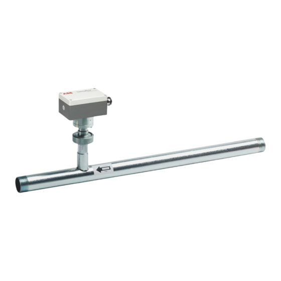
In this case, the exact gas com- position is to be specified with the order. The measuring systems FMT200-D consist of only the 2 components: • transducer and •... -
Page 10: Transducer (Detecting Element)
In addition, a flow-linearized analog signal of 0/4…20 mA (electrically isolated) is directly provided. No special supply/evaluation device is required. The transducer is screwed into pipe component as a plug-in sensor with a centering pin in a defined manner. See also chapter 10, “Technical Data”. Thermal Mass Flowmeter FMT200-D (Sensyflow D) 42/14-37 EN... -
Page 11: Mechanical Installation
(behind the measuring point). • When matching up the detecting element with a weld-on adapter, please read the information in chapter 4.5. Please make sure that the units are easily accessible when they are installed. 42/14-37 EN Thermal Mass Flowmeter FMT200-D (Sensyflow D) -
Page 12: Recommended Steadying Run Lengths For Inlet Run Disturbances
The inlet and outlet run lengths are stated as multiples of the pipe diameter D. For combinations of inlet run disturbances, e. g. valve and reducer, you must always consider the longer inlet run length. Thermal Mass Flowmeter FMT200-D (Sensyflow D) 42/14-37 EN... -
Page 13: Installation
Under certain circumstances, special calibration can be performed for insufficient steadying lengths. For this purpose and in individual cases, consult the DKD Calibration Department of ABB Automation Products GmbH at Alzenau. An on-site adjustment is also possible, if reference flow values are precisely known, by entering a calibration factor. -
Page 14: Weld-On Adapter For Fmt200-D (Sensyflow D)-Transducers
Mechanical installation Weld-on adapter for FMT200-D (Sensyflow D)-transducers NOTICE The weld-on adapter must be welded to the pipe always together with the cap-nut. It is not possible to mount the cap-nut after the welding process! Attach the cap-nut to the sensor connection nipple with a wire (or similar) while welding. - Page 15 – Push the transducer into the adapter and screw it together with the cap-nut. Centering pin Flow direction → Bild 4-2 Weld-on adapter DIN11851 mounted to pipeline, centering pin right (outflow side) 42/14-37 EN Thermal Mass Flowmeter FMT200-D (Sensyflow D)
-
Page 16: Electrical Installation
Fig. 5-2 Power supply 24 V AC / DC + Power supply 24 V AC / DC - Analog output 0/4...20 mA (electrically isolated) + Analog output 0/4...20 mA (electrically isolated) - Thermal Mass Flowmeter FMT200-D (Sensyflow D) 42/14-37 EN... - Page 17 Mark the mains switch accordingly to allow for a clear allocation to the respective equipment. Connect the power cable to the mains. Absolutely observe the notes in chapter 6 before switching on the power supply. 42/14-37 EN Thermal Mass Flowmeter FMT200-D (Sensyflow D)
-
Page 18: Start-Up - Safety Instructions
Prior to switching on the device make sure that all steps described in chapter 4 and chapter 5 have been executed properly. Check again that the operating voltage specified on the device is identical with the local mains voltage. After power-on, the device is automatically in operation. Thermal Mass Flowmeter FMT200-D (Sensyflow D) 42/14-37 EN... -
Page 19: Changing The Configuration
The standard setting in case of fault is 0...20 mA for (MAX.) and 4...20 mA for (MIN.). These settings can be modified via the LKS interface and the respective configuration software. Further fault messages (e.g. data error) can be received via the status function („Check function“, chapter 7). 42/14-37 EN Thermal Mass Flowmeter FMT200-D (Sensyflow D) -
Page 20: Maintenance
It can be assumed that safe operation is no longer possible – if the device shows visible signs of damage, – if the device does no longer work, – after long storage under unfavorable conditions, – after transport under unfavorable conditions. Thermal Mass Flowmeter FMT200-D (Sensyflow D) 42/14-37 EN... -
Page 21: Technical Data
– Totalizer with display (current-to-pulse converter) <1 kPa (10 mbar [0.145 psi]) at full scale decreasing quadratically for smaller flow rates Configuration The analog output of the FMT200-D (Sensyflow D) can be Ambient conditions switched between 0…20 mA and 4…20 mA. Ambient temperature for transducer Additionally, there is the opportunity to define a measurement -25…+70 °C... -
Page 22: Packaging For Transport
(at least sufficient for 3 months). Additionally line the box with a layer of union paper. Without exception, all returned ABB devices must be supplied with a decontamination confirmation (return-re- port) that has been completely filled out and signed by authorized specialist personnel (see chapter 2.2.2). Pro- cessing of the return is not possible without this confirmation. - Page 23 ABB has Sales & Customer Support The Company’s policy is one of continuous product expertise in over 100 countries worldwide. improvement and the right is reserved to modify the information contained herein without notice. www.abb.com/flow Printed in the Fed. Rep. of Germany (03.2008) ©...