Table of Contents
Advertisement
Quick Links
Outdoor Unit
SERVICE MANUAL
CAUTION
Before Servicing the unit, read the safety precautions in General SVC manual.
Only for authorized service personnel.
Any reproduction, duplication, distribution (including by way of email, facsimile or other electronic means), publication,
modification, copying or transmission of this Service Manual is STRICTLY PROHIBITED unless you have obtained
the prior written consent of the LG Electronics entity from which you received this Service Manual. The material
covered by this prohibition includes, without limitation, any text, graphics or logos in this Service Manual.
Copyright © 2020 LG Electronics Inc. All rights reserved. Only training and service purposes.
R410A
CONFIDENTIAL
Advertisement
Table of Contents

Related Manuals for LG Multi V ARWM072CAS5


Summary of Contents for LG Multi V ARWM072CAS5
- Page 1 Service Manual is STRICTLY PROHIBITED unless you have obtained the prior written consent of the LG Electronics entity from which you received this Service Manual. The material covered by this prohibition includes, without limitation, any text, graphics or logos in this Service Manual.
-
Page 2: Table Of Contents
Part 2 Outdoor units....................16 Part 3 HR Units ......................44 Part 4 PCB Setting and Test Run ................55 Part 5 Trouble shooting guide................87 - 2 - Copyright © 2020 LG Electronics. Inc. All right reserved. Only for training and service purposes... -
Page 3: Safety Precautions
• There is risk of fire, electric shock, explosion, or • There is risk of fire, electric shock, explosion, or injury. injury. - 3 - Copyright © 2020 LG Electronics. Inc. All right reserved. Only for training and service purposes... - Page 4 Should the refrigerant leak and cause the safety limit to be exceeded, harzards due to lack of oxygen in the room could result - 4 - Copyright © 2020 LG Electronics. Inc. All right reserved. Only for training and service purposes...
- Page 5 • To avoid vibration or water leakage. • If the gas leaks and accumulates around the unit, an explosion may result. - 5 - Copyright © 2020 LG Electronics. Inc. All right reserved. Only for training and service purposes...
- Page 6 • If the base collapses, the air conditioner could erate heat and cause a fire. fall with it, causing property damage, product failure, or personal injury. - 6 - Copyright © 2020 LG Electronics. Inc. All right reserved. Only for training and service purposes...
- Page 7 • Be careful and avoid personal injury. • There are sharp and moving parts that could cause personal injury. - 7 - Copyright © 2020 LG Electronics. Inc. All right reserved. Only for training and service purposes...
-
Page 8: Part 1 General Information
2.2 Outdoor unit................12 3. Combination of Outdoor units .............13 4. Nomenclature.................14 4.1 Indoor Unit ................14 4.2 Outdoor unit................14 4.3 HR Unit ..................15 - 8 - Copyright © 2020 LG Electronics. Inc. All right reserved. Only for training and service purposes... -
Page 9: Model Names
*Wall Mounted - L : Basic, R : Mirror *Ceiling Cassette - A : Basic, C : Plasma *Ceiling Concealed Duct - A : Basic, Z : FAU - 9 - Copyright © 2020 LG Electronics. Inc. All right reserved. Only for training and service purposes... -
Page 10: Outdoor Unit
1 Ph, 220-240 V, 50 Hz / 1 Ph, 220 V, 60 Hz PRHR063 PRHR083 1 Ph, 208/230 V, 60 Hz PRHR063A PRHR083A - 10 - Copyright © 2020 LG Electronics. Inc. All right reserved. Only for training and service purposes... -
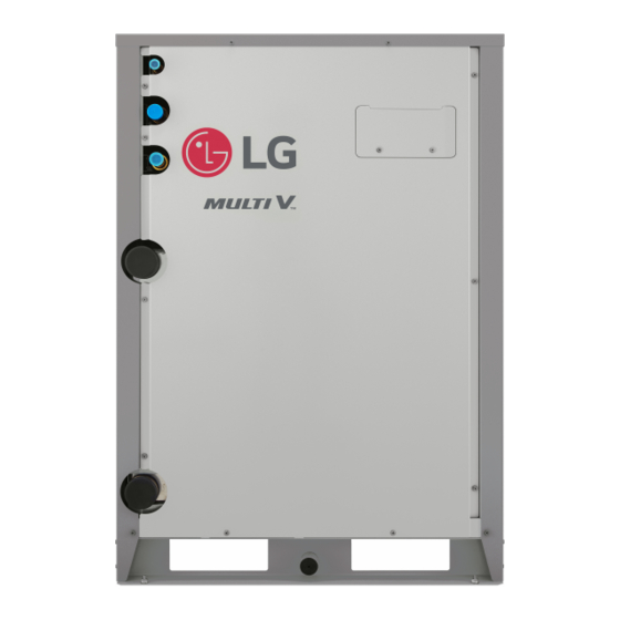
Page 11: External Appearance
ARNU093VEA2 ARNU243CFU4 ARNU123VEA2 Ceiling Suspended Vertical AHU URNU183VJA2 URNU243VJA2 ARNU123NJA4 ARNU183NJA4 Ceiling Cassette -2Way ARNU243NJA4 ARNU303NJA4 ARNU183TLC4 ARNU363NJA4 ARNU243TLC4 ARNU423NKA4 ARNU483NKA4 ARNU543NKA4 - 11 - Copyright © 2020 LG Electronics. Inc. All right reserved. Only for training and service purposes... -
Page 12: Outdoor Unit
2.2 Outdoor unit 2.2.1 Heat Recovery & Heat Pump Chassis Model Name Model ARWM072CAS5 ARWM096CAS5 ARWM121CAS5 ARWM144CAS5 ARWM192CAS5 ARWM240CAS5 ARWM288CAS5 ARWM336CAS5 ARWM432CAS5 ARWM480CAS5 ARWM576CAS5 - 12 - Copyright © 2020 LG Electronics. Inc. All right reserved. Only for training and service purposes... -
Page 13: Combination Of Outdoor Units
• The biggest module should be master module and others are slaves. • Setting method of master/slave and position of master in the system is explained in the installation chapter. - 13 - Copyright © 2020 LG Electronics. Inc. All right reserved. Only for training and service purposes... -
Page 14: Nomenclature
Heat Pump and Heat Recovery M : for both Heat Pump and Heat Recovery Indicates that this is Water System Outside Unit using the R410A - 14 - Copyright © 2020 LG Electronics. Inc. All right reserved. Only for training and service purposes... -
Page 15: Unit
08 : For 8 branches Indicates that this is System HR Unit using the R410A ※ These are model names of the basic function. - 15 - Copyright © 2020 LG Electronics. Inc. All right reserved. Only for training and service purposes... -
Page 16: Part 2 Outdoor Units
Part 2 Outdoor units - 16 - Copyright © 2020 LG Electronics. Inc. All right reserved. Only for training and service purposes... - Page 17 4.10 Vacuum Mode ......................39 4.11 Back up ........................40 4.12 Forced oil return .......................41 4.13 Cycle Data View.......................42 4.14 Refrigerant noise reduction mode ................43 - 17 - Copyright © 2020 LG Electronics. Inc. All right reserved. Only for training and service purposes...
-
Page 18: Basic Control
Inverter Comp 1 Comp 1 Comp 1 Cooling and heating load Fuzzy Control Inverter linear control as cooling and heating load increasing - 18 - Copyright © 2020 LG Electronics. Inc. All right reserved. Only for training and service purposes... -
Page 19: Master And Slave Unit's Eev Control
800 pls) and discharge temperature is above 85°C(185°F) in heating operation, subcooling EEV may con- trol the "subcooling out temperature-evaporating temperature" to be some given difference. - 19 - Copyright © 2020 LG Electronics. Inc. All right reserved. Only for training and service purposes... -
Page 20: Special Control
• Starting condition : When low oil level which is measured by oil level sensor is kept continuously then oil return operation will be start. • Oil return process ends if compressor protection control starts - 20 - Copyright © 2020 LG Electronics. Inc. All right reserved. Only for training and service purposes... - Page 21 • Oil return operation time : 3 min for running step • Starting condition:same as cooling mode • Oil return process ends if compressor protection control starts - 21 - Copyright © 2020 LG Electronics. Inc. All right reserved. Only for training and service purposes...
-
Page 22: Stop Operation
Inv Compressor Main EEV 32 pulse Subcooling EEV 16 pulse Stop(Min. pulse) 4way valve 1 OFF over 30°C(86°F) air temperature 4way valve 2 - 22 - Copyright © 2020 LG Electronics. Inc. All right reserved. Only for training and service purposes... -
Page 23: Protection Control
≤ 778 kPa(112.8 psi) Frequency holding ≤ 739 kPa(107.2 psi) -5Hz/7sec. h Frequency holding : frequency (or RPM) is not increasing (can decrease). - 23 - Copyright © 2020 LG Electronics. Inc. All right reserved. Only for training and service purposes... -
Page 24: Discharge Temperature Control
40 A or more h AC input current is input current of inverter compressor except constant current (current pass through noise filter) - 24 - Copyright © 2020 LG Electronics. Inc. All right reserved. Only for training and service purposes... -
Page 25: Other Control
Slave2 model code is displayed (3sec) Total capacity including sub units is displayed (2sec) Display 3 is default value Power type Model type - 25 - Copyright © 2020 LG Electronics. Inc. All right reserved. Only for training and service purposes... - Page 26 - Set the dip switch 3 to “Off” if not all the indoor units are “ARN*******4”. - When changing Dip switch, all power should be off and auto addressing must be executed. DIP Switch 7 segment - 26 - Copyright © 2020 LG Electronics. Inc. All right reserved. Only for training and service purposes...
- Page 27 Saving in Blank control option value EEPROM * Functions save in EEPROM will be kept continuously, though the system power was reset. - 27 - Copyright © 2020 LG Electronics. Inc. All right reserved. Only for training and service purposes...
- Page 28 Reduction mode value EEPROM * Functions save in EEPROM will be kept continuously, though the system power was reset. - 28 - Copyright © 2020 LG Electronics. Inc. All right reserved. Only for training and service purposes...
-
Page 29: Cool & Heat Selector
• If do not use a function, set an off-mode. • If use a function, first install a Cool & Heat selector. - 29 - Copyright © 2020 LG Electronics. Inc. All right reserved. Only for training and service purposes... -
Page 30: Outdoor Unit Address
Outdoor unit address mode is set CAUTION • Ask an authorized technician to setting a function. • If use a function, first install a Central controller. - 30 - Copyright © 2020 LG Electronics. Inc. All right reserved. Only for training and service purposes... -
Page 31: Idu Capacity Adjusting
- ON: Set to control the Low capacity mode - OFF: Set not to control CAUTION • Ask an authorized technician to setting a function. - 31 - Copyright © 2020 LG Electronics. Inc. All right reserved. Only for training and service purposes... -
Page 32: Target Pressure Adjusting
• Ask an authorized technician to setting a function. • If do not use a function, set an off-mode. • Change a power consumption or capacity. - 32 - Copyright © 2020 LG Electronics. Inc. All right reserved. Only for training and service purposes... -
Page 33: Geothermal Mode
12(54) 16(61) 24(75) 30(86) CAUTION • Ask an authorized technician to setting a function. • Anti freeze is essential for geothermal mode. - 33 - Copyright © 2020 LG Electronics. Inc. All right reserved. Only for training and service purposes... -
Page 34: Out For Solenoid Valve
- OFF: Set not to control the heat source water pipe Solenoid Valve from the product. CAUTION • Ask an authorized technician to setting a function. • If do not use a function, set an off mode. - 34 - Copyright © 2020 LG Electronics. Inc. All right reserved. Only for training and service purposes... -
Page 35: Variable Water Flow Control
- OFF: Set not to control the variable water flow control valve from the product CAUTION • Ask an authorized technician to setting a function. • If do not use a function, set an off mode. - 35 - Copyright © 2020 LG Electronics. Inc. All right reserved. Only for training and service purposes... -
Page 36: Pump Out
3. Pump out function takes 2~5 minutes after compressor start. Make certain that IDU doesn't run with thermo off mode during operation (in case low pressure doesn't go down) - 36 - Copyright © 2020 LG Electronics. Inc. All right reserved. Only for training and service purposes... - Page 37 (with vacuum mode) 6. Add the refrigerant with auto charging function Service Port Liquid pipe Low Pressure Gas pipe High Pressure Gas pipe - 37 - Copyright © 2020 LG Electronics. Inc. All right reserved. Only for training and service purposes...
- Page 38 (with vacuum mode) 6. Add the refrigerant with auto charging function Service Port Liquid pipe No Use(Keep closed) High Pressure Gas pipe - 38 - Copyright © 2020 LG Electronics. Inc. All right reserved. Only for training and service purposes...
-
Page 39: Vacuum Mode
Vacuum mode cancellation method Push the reset button on Master unit PCB CAUTION • ODU operation stops during vacuum mode. Compressor can't operate. - 39 - Copyright © 2020 LG Electronics. Inc. All right reserved. Only for training and service purposes... -
Page 40: Back Up
Select the Function using ‘▶’, ‘◀’ Button : “SE4” Push the ‘●’ button Back up mode is set CAUTION • Ask an authorized technician to setting a function. - 40 - Copyright © 2020 LG Electronics. Inc. All right reserved. Only for training and service purposes... -
Page 41: Forced Oil Return
Starting oil return with display “OI” · Auto reset after oil return completed. CAUTION • Ask an authorized technician to setting a function. - 41 - Copyright © 2020 LG Electronics. Inc. All right reserved. Only for training and service purposes... -
Page 42: Cycle Data View
16 pls op22 hc eev PLS4 50 pls op25 IDU running capacity IDU1 24 kBtu op26 Total number of IDU IDU2 10 EA - 42 - Copyright © 2020 LG Electronics. Inc. All right reserved. Only for training and service purposes... -
Page 43: Refrigerant Noise Reduction Mode
Normal mode (Fast cooling & Fast heating) : Off Save the selected option value in EEROM CAUTION • Ask an authorized technician to setting a function. - 43 - Copyright © 2020 LG Electronics. Inc. All right reserved. Only for training and service purposes... -
Page 44: Part 3 Hr Units
Part 3 HR Units - 44 - Copyright © 2020 LG Electronics. Inc. All right reserved. Only for training and service purposes... - Page 45 HR Units 1. Specifications ........................46 2. Parts Functions ......................48 3. Dimensions ........................49 4. Piping Diagrams ......................51 5. Wiring Diagrams ......................52 6. Functions ........................53 - 45 - Copyright © 2020 LG Electronics. Inc. All right reserved. Only for training and service purposes...
-
Page 46: Specifications
(Next lower standard fuse rating. Min. 15 A) 4. Select wire size based on the MCA 5. Instead of fuse, use circuit. - 46 - Copyright © 2020 LG Electronics. Inc. All right reserved. Only for training and service purposes... - Page 47 (Next lower standard fuse rating. Min. 15 A) 4. Select wire size based on the MCA 5. Instead of fuse, use circuit. - 47 - Copyright © 2020 LG Electronics. Inc. All right reserved. Only for training and service purposes...
-
Page 48: Parts Functions
Low pressure gas pipe Subcooling EEV Liquid bypass valve Balancing valve Gas pipe Liquid pipe (to Indoor unit) Solenoid assembly 1 Solenoid assembly 2 - 48 - Copyright © 2020 LG Electronics. Inc. All right reserved. Only for training and service purposes... -
Page 49: Dimensions
Dimensions Dimensions 1. HR Units - 49 - Copyright © 2020 LG Electronics. Inc. All right reserved. Only for training and service purposes... - Page 50 Dimensions - 50 - Copyright © 2020 LG Electronics. Inc. All right reserved. Only for training and service purposes...
-
Page 51: Piping Diagrams
Ⓒ : To prevent liquid charging between high pressure gas valve and HR unit at cooling mode Ⓓ : To be controlled the pressure between high and low pressure pipe during operation switching - 51 - Copyright © 2020 LG Electronics. Inc. All right reserved. Only for training and service purposes... -
Page 52: Wiring Diagrams
Wiring Diagrams Wiring Diagrams 1. HR Units - 52 - Copyright © 2020 LG Electronics. Inc. All right reserved. Only for training and service purposes... -
Page 53: Functions
Cooling mode : Close Keep Close Heating mode : Stop or ventilation Low pressure Timer = 0 Keep Close gas valve ➞ Close - 53 - Copyright © 2020 LG Electronics. Inc. All right reserved. Only for training and service purposes... - Page 54 Subcooling EEV works with Fuzzy rules to keep the degree of subcooling at the outlet of subcooler during simultaneous operation The degree of subcooler = T outlet of subcooler – T inlet of subcooler - 54 - Copyright © 2020 LG Electronics. Inc. All right reserved. Only for training and service purposes...
-
Page 55: Part 4 Pcb Setting And Test Run
Part 4 PCB Setting and Test Run - 55 - Copyright © 2020 LG Electronics. Inc. All right reserved. Only for training and service purposes... - Page 56 7. Identification of Manual Valve ID (Address) ............83 Test Run ..........................84 1. Checks Before Test Run..................84 2. How to Cope with Test Run Abnormality .............85 3. Dip Switch Setting....................85 - 56 - Copyright © 2020 LG Electronics. Inc. All right reserved. Only for training and service purposes...
-
Page 57: Unit Pcb (Prhr042A, Prhr032A, Prhr022A)
DIP S/W setting Normal control SW01M Turn the dip switch of the zoning branch on. Zoning Ex) Branch 1,2 are zoning control. control SW01M - 57 - Copyright © 2020 LG Electronics. Inc. All right reserved. Only for training and service purposes... - Page 58 • If you want to use a PRHR042A for 2 branches HR unit after closing the 3rd and 4th pipes, set the dip switch for 2 branches HR unit. • The unused port must be closed with a copper cap, not with a plastic cap. - 58 - Copyright © 2020 LG Electronics. Inc. All right reserved. Only for training and service purposes...
- Page 59 321(12-5/8) I.D28.58(1-1/8) I.D12.7(1/2) O.D15.88(5/8) I.D9.52(3/8) 332(13-1/16) O.D19.05(3/4) O.D19.05(3/4) O.D25.4(1) I.D25.4(1) 70(2-3/4) 80(3-5/32) 110(4-11/32) 70(2-3/4) 110(4-11/32) For more information, refer accessory installation manual. - 59 - Copyright © 2020 LG Electronics. Inc. All right reserved. Only for training and service purposes...
- Page 60 Manual addressing of valve #4 SW03M SW03M Increase in the digit of 10 of valve address SW04M Increase in the last digit of valve address SW04M - 60 - Copyright © 2020 LG Electronics. Inc. All right reserved. Only for training and service purposes...
- Page 61 Increase in the digit of 10 of valve address SW03M SW04M Increase in the last digit of valve address SW04M SW05M Manual addressing of zoning indoor units SW05M - 61 - Copyright © 2020 LG Electronics. Inc. All right reserved. Only for training and service purposes...
-
Page 62: Automatic Addressing
• Automatic Addressing is only possible on the master Unit. • Automatic Addressing has to be performed after 3 minutes to improve communica- tion. - 62 - Copyright © 2020 LG Electronics. Inc. All right reserved. Only for training and service purposes... -
Page 63: Flow Chart For Chart For Auto-Addressing Of Indoor And Hr Unit
Display of 01, 02, ..., 15 means connection of 15 indoor units and Automatic addressing is completed normally. - 63 - Copyright © 2020 LG Electronics. Inc. All right reserved. Only for training and service purposes... - Page 64 ※It is possible to be generated mode changing noise of heating and cooling which is normal. There is no mode changing noise at normal operation. - 64 - Copyright © 2020 LG Electronics. Inc. All right reserved. Only for training and service purposes...
- Page 65 Completion of manual pipe detection Make sure that reset the outdoor unit power when changing the central control unit Reset the power of outdoor unit PCB. - 65 - Copyright © 2020 LG Electronics. Inc. All right reserved. Only for training and service purposes...
-
Page 66: Example Of Manual Valve Addressing(Non-Zoning Setting)
- The valve that is not connected with any indoor unit should be addressed with any other number than used address numbers of the valves connected with indoor units. (The valves does not work if the address numbers are same.) - 66 - Copyright © 2020 LG Electronics. Inc. All right reserved. Only for training and service purposes... -
Page 67: Example Of Manual Valve Addressing (Zoning Setting)
- The valve that is not connected with any indoor unit should be addressed with any other number than used address numbers of the valves connected with indoor units. (The valves does not work if the address numbers are same.) - 67 - Copyright © 2020 LG Electronics. Inc. All right reserved. Only for training and service purposes... -
Page 68: Example Of Checking Valve Address
Display and setup Setup and contents • Operation: more than 2 dip switches turned on. • Display: "Er" is displayed in 7-SEG SW01M - 68 - Copyright © 2020 LG Electronics. Inc. All right reserved. Only for training and service purposes... -
Page 69: Unit Pcb (Prhr**3A, ** : 02, 03, 04, 06, 08)
* Number from left in sequence for less-than-8 branch model. ** PRHR043 / PRHR043A / PRHR033 / PRHR033A / PRHR023 / PRHR023A : Master Only - 69 - Copyright © 2020 LG Electronics. Inc. All right reserved. Only for training and service purposes... -
Page 70: Switch For Setup Of Hr Unit
EEPROM factory initialization (4,5,6) No.7 Use only in factory production (preset to "OFF") Zoning setting ("ON") No.8 Use only in factory production (preset to "OFF") - 70 - Copyright © 2020 LG Electronics. Inc. All right reserved. Only for training and service purposes... - Page 71 Slave Switch No.5 Off Switch No.5 On NOTE Do not turn on any SW02E on Slave Main PCB except No.5. Slave Slave - 71 - Copyright © 2020 LG Electronics. Inc. All right reserved. Only for training and service purposes...
- Page 72 Ex) If you want to use a PRHR083 for 4 branches HR Unit after closing the 5~8th pipes, set the dip switch for 4 branches HR Unit. - 72 - Copyright © 2020 LG Electronics. Inc. All right reserved. Only for training and service purposes...
- Page 73 I.D12.7(1/2) I.D28.58(1-1/8) 332(13-1/16) I.D12.7(1/2) O.D15.88(5/8) O.D19.05(3/4) I.D9.52(3/8) O.D19.05(3/4) O.D25.4(1) I.D25.4(1) 80(3-5/32) 70(2-3/4) 70(2-3/4) 110(4-11/32) 110(4-11/32) For more information, refer accessory installation manual. - 73 - Copyright © 2020 LG Electronics. Inc. All right reserved. Only for training and service purposes...
- Page 74 - Prerequisite for Manual pipe detection : central control address of each indoor unit must be preset differently at its wired remote control. - 74 - Copyright © 2020 LG Electronics. Inc. All right reserved. Only for training and service purposes...
- Page 75 SW #2 On : Select Valve #6 Input the central control SW #2 Off : Finish Valve #6 address of Indoor unit - 75 - Copyright © 2020 LG Electronics. Inc. All right reserved. Only for training and service purposes...
- Page 76 SW #2 On : Select Valve #6 Input the central control SW #2 Off : Finish Valve #6 address of Indoor unit - 76 - Copyright © 2020 LG Electronics. Inc. All right reserved. Only for training and service purposes...
-
Page 77: Automatic Addressing
• Automatic Addressing is only possible on the master Unit. • Automatic Addressing has to be performed after 3 minutes to improve communica- tion. - 77 - Copyright © 2020 LG Electronics. Inc. All right reserved. Only for training and service purposes... -
Page 78: Flow Chart For Chart For Auto-Addressing Of Indoor And Hr Unit
Display of 01, 02, ..., 15 means connection of 15 indoor units and Automatic addressing is completed normally. - 78 - Copyright © 2020 LG Electronics. Inc. All right reserved. Only for training and service purposes... - Page 79 ※It is possible to be generated mode changing noise of heating and cooling which is normal. There is no mode changing noise at normal operation. - 79 - Copyright © 2020 LG Electronics. Inc. All right reserved. Only for training and service purposes...
- Page 80 Completion of manual pipe detection Make sure that reset the outdoor unit power when changing the central control unit Reset the power of outdoor unit PCB. - 80 - Copyright © 2020 LG Electronics. Inc. All right reserved. Only for training and service purposes...
-
Page 81: Example Of Manual Valve Addressing(Non-Zoning Setting)
- The valve that is not connected with any indoor unit should be addressed with any other number than used address numbers of the valves connected with indoor units. (The valves does not work if the address numbers are same.) - 81 - Copyright © 2020 LG Electronics. Inc. All right reserved. Only for training and service purposes... -
Page 82: Example Of Manual Valve Addressing(Zoning Setting)
- The valve that is not connected with any indoor unit should be addressed with any other number than used address numbers of the valves connected with indoor units.(The valves does not work if the address numbers are same.) - 82 - Copyright © 2020 LG Electronics. Inc. All right reserved. Only for training and service purposes... -
Page 83: Example Of Checking Valve Address
• The zoning information and Master IDU information remove from EEPROM after Auto-addressing. • If there is installed the central control, it is impossible setting of Master IDU in zoning. - 83 - Copyright © 2020 LG Electronics. Inc. All right reserved. Only for training and service purposes... -
Page 84: Test Run
• In case that the outdoor temperature is low, be sure to supply power 4 hours before operation so that the heater is heated(insufficient heating may cause damage of the compressor.) - 84 - Copyright © 2020 LG Electronics. Inc. All right reserved. Only for training and service purposes... -
Page 85: How To Cope With Test Run Abnormality
7 - Segment SW04C (X : cancel) SW03C ( : forward) SW02C ( : backward) SW01C ( : Confirm / Automatic Addressing) SW04D (reset) - 85 - Copyright © 2020 LG Electronics. Inc. All right reserved. Only for training and service purposes... - Page 86 (Installer Setting) restart the system. (If you turn on the DIP s/w No 4, you can make sure “HR” or “HP” display later.) - 86 - Copyright © 2020 LG Electronics. Inc. All right reserved. Only for training and service purposes...
-
Page 87: Part 5 Trouble Shooting Guide
Part 5 Trouble shooting guide - 87 - Copyright © 2020 LG Electronics. Inc. All right reserved. Only for training and service purposes... - Page 88 2.4 Inverter IPM/IGBT Checking Method............94 2.5 Pressure Sensor(High/Low Pressure Sensor) ........95 2.6 Reverse Valve....................96 2.7 Temperature Sensor .................97 2.8 Others ......................98 3. Self-diagnosis function ..............99 - 88 - Copyright © 2020 LG Electronics. Inc. All right reserved. Only for training and service purposes...
-
Page 89: The Phenomena From Main Component Failure
The trouble shooting guide is available in the service manual. • When CH05/53/11 ERROR occurs, check if auto-addressing has done and communication wiring is ok. - 89 - Copyright © 2020 LG Electronics. Inc. All right reserved. Only for training and service purposes... -
Page 90: Checking Method For Key Components
(when measuring absolute values). Accurate measuring values cannot be obtained with a general movable tester (For analog and digital mode). - 90 - Copyright © 2020 LG Electronics. Inc. All right reserved. Only for training and service purposes... -
Page 91: Electronic Expansion Valve
EEV surface with a screw driver and listening the Full open EEV noise. open 1950 pulses - If liquid refrigerant is in EEV, the noise is lower. pulse - 91 - Copyright © 2020 LG Electronics. Inc. All right reserved. Only for training and service purposes... - Page 92 Unit connection 2. After removing the connector on the control board and connected part Indoor or assembly check with tester. Unit - 92 - Copyright © 2020 LG Electronics. Inc. All right reserved. Only for training and service purposes...
-
Page 93: Inverter Bridge Diode Checking Method
• Check the electric parts of c/box, 10 minutes after switching off the main supply and checking DC voltage is discharged. Otherwise, there is chance of getting electric shock. • There is chance of electric shock by charged voltage. - 93 - Copyright © 2020 LG Electronics. Inc. All right reserved. Only for training and service purposes... -
Page 94: Inverter Ipm/Igbt Checking Method
6. In case measured value is different from the table, PCB needs to be replaced.(PCB damaged). ] Red(+) and black(-) are the measuring terminals of multi tester. - 94 - Copyright © 2020 LG Electronics. Inc. All right reserved. Only for training and service purposes... -
Page 95: Pressure Sensor(High/Low Pressure Sensor)
The pressure which is equivalent to the pressure output is shown in the table above. - 95 - Copyright © 2020 LG Electronics. Inc. All right reserved. Only for training and service purposes... -
Page 96: Reverse Valve
6. Insulation resistance in the state of connecting the valve to coil should be over 100mΩ when measure it with DC mega tester(DC 500V). - 96 - Copyright © 2020 LG Electronics. Inc. All right reserved. Only for training and service purposes... -
Page 97: Temperature Sensor
2. Check whether the connector contact of temperature sensor is normal. 3. Measure the resistance of temperature sensor. 10KΩ±1%[25°C(77°F)] 5KΩ±1%[25°C(77°F)] 200KΩ±1%[25°C(77°F)] Resistance 1.07KΩ±3.3%[85°C(185°F)] 535Ω±3.3%[85℃(185℉)] 28KΩ±7.7%[85°C(185°F)] - 97 - Copyright © 2020 LG Electronics. Inc. All right reserved. Only for training and service purposes... -
Page 98: Others
3) Set the multi meter to resistance mode, confirm that the resistance value of the resistor is around 270 kOhm Check and replace inferior components - 98 - Copyright © 2020 LG Electronics. Inc. All right reserved. Only for training and service purposes... -
Page 99: Self-Diagnosis Function
Temperature sensor Error Hydro Kit Indoor unit Outlet pipe 1 8 - Pipe temperature sensor is open or short Temperature sensor Error - 99 - Copyright © 2020 LG Electronics. Inc. All right reserved. Only for training and service purposes... - Page 100 Master Outdoor Unit Air Master Outdoor Unit Air Temperature Sensor 4 4 * Temperature Sensor Fault open or short - 100 - Copyright © 2020 LG Electronics. Inc. All right reserved. Only for training and service purposes...
- Page 101 Water inlet temperature sensor open or short 1 8 9 * Flow switch error Heat water not supplied or flow rate is insufficient - 101 - Copyright © 2020 LG Electronics. Inc. All right reserved. Only for training and service purposes...
- Page 102 • To use open line 485 communication (9,600 bps communication), you need to use a product in which all of the indoor unit/HR unit/outdoor unit/accessory model can use (9,600 bps communication). - 102 - Copyright © 2020 LG Electronics. Inc. All right reserved. Only for training and service purposes...
- Page 103 CN-PIPE IN : Pipe inlet temp sensor CN-PIPE OUT : Pipe outlet temp sensor Measure the resistance of outlet pipe temp sensor. - 103 - Copyright © 2020 LG Electronics. Inc. All right reserved. Only for training and service purposes...
- Page 104 CN-REMO : Remote controller connection ❇ The PCB can differ from model to model. Check from the right source. Checking communication cable connection status - 104 - Copyright © 2020 LG Electronics. Inc. All right reserved. Only for training and service purposes...
- Page 105 * If the float goes up higher than a half of float switch then the circuit is open & the unit is stopped automatically. (High position Open) float Condensate water - 105 - Copyright © 2020 LG Electronics. Inc. All right reserved. Only for training and service purposes...
- Page 106 (Marked as CN-DPUMP) Float switch Housing (CN-FLOAT) [***] Standard of drain pipe head height / slope MAX 450mm (17-23/32inch) MAX 700mm (27-9/16inch) - 106 - Copyright © 2020 LG Electronics. Inc. All right reserved. Only for training and service purposes...
- Page 107 ~ +9V) exists when checking DC voltage of indoor unit is fluctuate within (-9V~+9V) then of communication terminal between IDU and ODU communication from outdoor unit is normal - 107 - Copyright © 2020 LG Electronics. Inc. All right reserved. Only for training and service purposes...
- Page 108 Error diagnosis and countermeasure flow chart - Replace the indoor unit PCB, and then make sure to perform Auto addressing and input the address of central control - 108 - Copyright © 2020 LG Electronics. Inc. All right reserved. Only for training and service purposes...
- Page 109 WARNING • The connection of motor connector to PCB should be done under no power supplying to PCB. - 109 - Copyright © 2020 LG Electronics. Inc. All right reserved. Only for training and service purposes...
- Page 110 PCB. Note. 1. Apply thermal grease at heat sink if needed. 2. Carefully reconnect the wires with out interchanging the locations. - 110 - Copyright © 2020 LG Electronics. Inc. All right reserved. Only for training and service purposes...
- Page 111 Check Inverter PCB assembly IPM normality. Is Inverter PCB assembly → Replace Inverter PCB assembly normal? if abnormality found. Recheck power and installation condition - 111 - Copyright © 2020 LG Electronics. Inc. All right reserved. Only for training and service purposes...
- Page 112 Self-diagnosis function IPM(IGBT) joining point Compressor wire connector connection point • Check DC Link connector joining condition - 112 - Copyright © 2020 LG Electronics. Inc. All right reserved. Only for training and service purposes...
- Page 113 Check Inverter PCB assembly IPM normality Is Inverter PCB assembly → Replace Inverter PCB assembly normal? Recheck power and installation condition - 113 - Copyright © 2020 LG Electronics. Inc. All right reserved. Only for training and service purposes...
- Page 114 Self-diagnosis function * Measuring input voltage * Compressor wire connector connection - 114 - Copyright © 2020 LG Electronics. Inc. All right reserved. Only for training and service purposes...
- Page 115 Check Inverter PCB assembly IPM normality. Is Inverter PCB assembly → Replace Inverter PCB assembly if abnormality found. normal? Recheck power and installation condition - 115 - Copyright © 2020 LG Electronics. Inc. All right reserved. Only for training and service purposes...
- Page 116 Self-diagnosis function * Check DC_Link Connector joining condition * Measuring input voltage DC Link Connector - 116 - Copyright © 2020 LG Electronics. Inc. All right reserved. Only for training and service purposes...
- Page 117 Is high pressure of LGMV similar as Replace high pressure sensor at manifold gauge? Check pipe is blocked or not and take measure - 117 - Copyright © 2020 LG Electronics. Inc. All right reserved. Only for training and service purposes...
- Page 118 Check bridge diode in IGBTM of Inverter PCB bridge diode joining condition normal? Replace Inverter PCB assembly. Inverter PCB LED display error Recheck power and installation condition - 118 - Copyright © 2020 LG Electronics. Inc. All right reserved. Only for training and service purposes...
- Page 119 → Reassemble if abnormality found Check Inverter PCB assembly IPM normality Is Inverter PCB assembly normal? → Replace Inverter PCB assembly Recheck power and installation condition - 119 - Copyright © 2020 LG Electronics. Inc. All right reserved. Only for training and service purposes...
- Page 120 Self-diagnosis function * Compressor wire connection - 120 - Copyright © 2020 LG Electronics. Inc. All right reserved. Only for training and service purposes...
- Page 121 Check Inverter PCB assembly IPM normality Is Inverter PCB assembly normal? → Replace Inverter PCB assembly Recheck power and installation condition - 121 - Copyright © 2020 LG Electronics. Inc. All right reserved. Only for training and service purposes...
- Page 122 Self-diagnosis function * Measuring input voltage * Compressor wire connection - 122 - Copyright © 2020 LG Electronics. Inc. All right reserved. Only for training and service purposes...
- Page 123 Replace outdoor unit EEV [refer electric component part] Check another components Is there pipe and operation conditions (strainer etc.) clogging? / Take measures Replace strainer - 123 - Copyright © 2020 LG Electronics. Inc. All right reserved. Only for training and service purposes...
- Page 124 Manifold Replace sensor of high pressure value(Is it high actually)? Check indoor unit LEV Check indoor unit PCB Check in/outdoor installation condition - 124 - Copyright © 2020 LG Electronics. Inc. All right reserved. Only for training and service purposes...
- Page 125 (Notice: it is not full ice forming of strainer, in case that there is installation conditions not at inlet portion but at outlet portion) - 125 - Copyright © 2020 LG Electronics. Inc. All right reserved. Only for training and service purposes...
- Page 126 * Measuring input voltage * Inverter PCB assembly R(L1) R(L1) R(L1) R(L1) R(L1) R(L1) R(L1) S(L2) S(L2 ( L2) (L2) T(L3) (L3) - 126 - Copyright © 2020 LG Electronics. Inc. All right reserved. Only for training and service purposes...
- Page 127 10 ℃ [50 ℉] = 362 kΩ : 25 ℃ [77 ℉] = 200 kΩ : 50 ℃[122 ℉] = 82 kΩ : 100 ℃ [212 ℉]= 18.5 kΩ Check the resistance inverter compressor discharge temperature sensor - 127 - Copyright © 2020 LG Electronics. Inc. All right reserved. Only for training and service purposes...
- Page 128 PCB pressure sensor is the system normal? High pressure sensor Pressure sensor connector Low pressure sensor High pressure sensor Low pressure sensor - 128 - Copyright © 2020 LG Electronics. Inc. All right reserved. Only for training and service purposes...
- Page 129 Sensor of piping temperature: 10 ℃ [50 ℉] = 10 kΩ : 25 ℃ [77 ℉] = 5 kΩ : 50 ℃[122 ℉] = 1.8 kΩ - 129 - Copyright © 2020 LG Electronics. Inc. All right reserved. Only for training and service purposes...
- Page 130 Recheck power and installation condition * Measuring input voltage * Noise filter wiring * Field Fault Case T S R * R-Phase Terminal Changed Color. - 130 - Copyright © 2020 LG Electronics. Inc. All right reserved. Only for training and service purposes...
- Page 131 * In order to check communication cables between outdoor units, ➠ ➠ check in order as below : PCB connectors terminal block communication cables - 131 - Copyright © 2020 LG Electronics. Inc. All right reserved. Only for training and service purposes...
- Page 132 Replace Main PCB Replace Comp PCB * The method of checking Main PCB and Inverter 2 PCB (If normal, communication LED blinks) - 132 - Copyright © 2020 LG Electronics. Inc. All right reserved. Only for training and service purposes...
- Page 133 * After replacement of indoor unit PCB, Auto Addressing should be done, if central controller is installed then the central control address also should be input. In case that only communication PCB is replaced above process is not needed - 133 - Copyright © 2020 LG Electronics. Inc. All right reserved. Only for training and service purposes...
- Page 134 Self-diagnosis function External PCB Main PCB Indoor Unit Communication PCB Wiring Fault Case - 134 - Copyright © 2020 LG Electronics. Inc. All right reserved. Only for training and service purposes...
- Page 135 Is there any error 1. Replace Main PCB when power reset? Recheck power and installation condition Inverter PCB Main PCB Communication LED Communication LED - 135 - Copyright © 2020 LG Electronics. Inc. All right reserved. Only for training and service purposes...
- Page 136 Recheck power and installation condition * Inverter EEPROM inserting point Check IC02L * Right inserting direction of inverter EEPROM ❊ Note : Replace after power off - 136 - Copyright © 2020 LG Electronics. Inc. All right reserved. Only for training and service purposes...
- Page 137 Normal? Replace Inverter PCB Assembly Recheck Power and Installation Condition n Check Inverter PCB Screw Connection Condition ❈ Check screw connection condition - 137 - Copyright © 2020 LG Electronics. Inc. All right reserved. Only for training and service purposes...
- Page 138 Pipe temperature sensor: 10 ℃ [50 ℉] = 10 kΩ : 25 ℃ [77 ℉] = 5 kΩ : 50 ℃ [122 ℉] = 1.8 kΩ - 138 - Copyright © 2020 LG Electronics. Inc. All right reserved. Only for training and service purposes...
- Page 139 Recheck power and installation condition EEPROM Insertion EEPROM * Note : Replace after power off Same direction both socket hole and EEPROM hole - 139 - Copyright © 2020 LG Electronics. Inc. All right reserved. Only for training and service purposes...
- Page 140 Is Slave Unit DIP SW DIP SW setting setting done? Is Main PCB power Connect power cable supplied? Replace Main PCB - 140 - Copyright © 2020 LG Electronics. Inc. All right reserved. Only for training and service purposes...
- Page 141 Air temperature sensor: 10℃[50℉] = 20.7kΩ : 25℃[77℉] = 10kΩ : 50℃[122℉]= 3.4kΩ Pipe temperature sensor: 10℃[50℉] = 10kΩ : 25℃[77℉] = 5kΩ : 50℃[122℉]= 1.8kΩ - 141 - Copyright © 2020 LG Electronics. Inc. All right reserved. Only for training and service purposes...
- Page 142 Is Main PCB normal Replace Main PCB Replace External PCB * The Method of checking Main PCB and External PCB (If normal, communication LED blinks) - 142 - Copyright © 2020 LG Electronics. Inc. All right reserved. Only for training and service purposes...
- Page 143 1) Ref. leakage much : Both Pipe in, pipe out temp. is under 10℃[50℉] during unit is off(EEV 40pls) Also, big refrigerant flow noise occured - 143 - Copyright © 2020 LG Electronics. Inc. All right reserved. Only for training and service purposes...
- Page 144 If the same error is occurred in mode, is the same error near future replace 4way valve occurred again? Replace 4 way valve***** - 144 - Copyright © 2020 LG Electronics. Inc. All right reserved. Only for training and service purposes...
- Page 145 √ If there is a unit in which the difference is not increased then the 4way valve of that unit is defective - 145 - Copyright © 2020 LG Electronics. Inc. All right reserved. Only for training and service purposes...
- Page 146 Air temperature sensor: 10 °C = 20.7 kΩ : 25 °C = 10 kΩ : 50 °C = 3.4 kΩ Pipe temperature sensor: 10 °C = 10 kΩ : 25 °C = 5 kΩ : 50 °C = 1.8 kΩ - 146 - Copyright © 2020 LG Electronics. Inc. All right reserved. Only for training and service purposes...
- Page 147 Air temperature sensor: 10 °C = 20.7 kΩ : 25 °C = 10 kΩ : 50 °C = 3.4 kΩ Pipe temperature sensor: 10 °C = 10 kΩ : 25 °C = 5 kΩ : 50 °C = 1.8 kΩ - 147 - Copyright © 2020 LG Electronics. Inc. All right reserved. Only for training and service purposes...
- Page 148 Error diagnosis and countermeasure flow chart Communication Between Main-Sub Micom LED (Yellow) Blinking ’ Press the Rest Button Replay Replace External PCB On-boarding - 148 - Copyright © 2020 LG Electronics. Inc. All right reserved. Only for training and service purposes...
- Page 149 1. Check 5(A)/5(B) wiring conditions ’ wire connections normal? Rewire them if abnormality found Is flow switch normal? Replace flow switch Replace outdoor unit PCB - 149 - Copyright © 2020 LG Electronics. Inc. All right reserved. Only for training and service purposes...
- Page 150 Network and Outdoor Unit (It flash on and off when communication is normally between Network and Outdoor Unit) <RS-485 communication wire miss connection> - 150 - Copyright © 2020 LG Electronics. Inc. All right reserved. Only for training and service purposes...
- Page 151 [NB] How to check display method of outdoor main PCB 7-segment ?: '88' ‘ Indoor qty which check thru 'Auto-Addressing' ‘ '88' ‘ Indoor qty which check thru ‘piping checking' - 151 - Copyright © 2020 LG Electronics. Inc. All right reserved. Only for training and service purposes...
- Page 152 Example of HR unit error display. #16 HR unit Sub-cooling inlet pipe temperature sensor error 200 ‘ C16 (Repeat) C: HR unit #: HR unit Nuber - 152 - Copyright © 2020 LG Electronics. Inc. All right reserved. Only for training and service purposes...
- Page 153 [NB] If Indoor units/communication cables of HR unit and cables of power 220 V has been changed each other, communication parts and indoor will be burnt - 153 - Copyright © 2020 LG Electronics. Inc. All right reserved. Only for training and service purposes...
- Page 154 Bypass No.5 SW02B/SW01B/SW02E Valve - SW01E : Branch #5~8 - SW01E : Branch #1~4 (from (from SW No.1) SW No.1) - SW01C - 154 - Copyright © 2020 LG Electronics. Inc. All right reserved. Only for training and service purposes...
- Page 155 • Refer to the installation manual of the outdoor unit for the address setting to HR unit rotary switch for HR units Upgraded 485 Modem - 155 - Copyright © 2020 LG Electronics. Inc. All right reserved. Only for training and service purposes...
- Page 156 1) Check the wiring connection between EEPROM and Main PCB of HR Unit. 2) Replace Main PCB of HR Unit even after check No.1 process. - 156 - Copyright © 2020 LG Electronics. Inc. All right reserved. Only for training and service purposes...
- Page 157 P/NO : MFL71707501 Copyright © 2020 LG Electronics Inc. All rights reserved. Only training and service purposes.