Table of Contents
Advertisement
INSTALLATION MANUAL
AIR
CONDITIONER
Please read this installation manual completely before installing the product.
Installation work must be performed in accordance with the national wiring standards by
authorized personnel only.
Please retain this installation manual for future reference after reading it thoroughly.
For Heat Pump / Heat Recovery system
Original instruction
MFL71705501
Rev.02_120420
Copyright © 2020 LG Electronics Inc. All Rights Reserved.
www.lghvac.com
www.lg.com
Advertisement
Table of Contents

Related Manuals for LG Multi V PRHR033


Summary of Contents for LG Multi V PRHR033
- Page 1 Installation work must be performed in accordance with the national wiring standards by authorized personnel only. Please retain this installation manual for future reference after reading it thoroughly. For Heat Pump / Heat Recovery system Original instruction www.lghvac.com www.lg.com MFL71705501 Rev.02_120420 Copyright © 2020 LG Electronics Inc. All Rights Reserved.
-
Page 2: Tips For Saving Energy
Installation TIPS FOR SAVING ENERGY • Have all electric work done by a licensed electrician according to "Electric Facility Engineering Standard" and "Interior Wire Regulations" Here are some tips that will help you minimize the power consumption and the instructions given in this manual and always use a special when you use the air conditioner. -
Page 3: Table Of Contents
CAUTION TABLE OF CONTENTS Installation TIPS FOR SAVING ENERGY • Always check for gas (refrigerant) leakage after installation or repair of product. - Low refrigerant levels may cause failure of product. IMPORTANT SAFETY INSTRUCTIONS • Do not install the product where the noise or hot air from the outdoor unit could damage the neighborhoods. -
Page 4: Installation Process
INSTALLATION PROCESS ALTERNATIVE REFRIGERANT R410A The refrigerant R410A has the property of higher operating pressure in Indicate clearly who will be responsible for switch setting. Determination of division work comparison with R22. Therefore, all materials have the characteristics of higher resisting Make connection clearly between outside, indoor, Preparation of contract drawings remote controller and option. - Page 5 CAUTION PRHR063(A)/PRHR083(A) [Unit : mm(inch)] • Do not install Multi V water outdoors. Always install indoor like machine room. • Inverter product may generate electric noise. Keep the body from 6(1/4) more 809(31-27/32) (Serviceing space) computer, stereo etc. at enough distance. Specially leave space from indoor remote controller to shoes electric devices at the above 3m in weak electric wave area.
-
Page 6: Installation Space
INSTALLATION SPACE WATER CONTROL Individual Installation Water control During the installation of the unit, consider service, inlet, and outlet • Keep the water temperature between 10~45 °C (50~113 °F). Other it acquire the minimum space as shown in the figures below. may cause the breakdown. - Page 7 CAUTION Closed type Effect Items Circulating water Supplemented water Corrosion Scale Basic Item Be very careful while carrying the product. pH(25°C) 7.0~8.0 7.0~8.0 • Do not have only one person carry product if it is more than 20 Conductivity[25°C](mS/m) Below 30 Below 30 kg (44 lbs).
- Page 8 Foundation for Installation Preparation of Piping • Fix the unit tightly with bolts as shown below so that unit will not fall Main cause of gas leakage is defect in flaring work. Carry out correct down due to earthquake or gust. flaring work in the following procedure.
- Page 9 Flare shape and flare nut tightening torque Heat insulation Precautions when connecting pipes Use the heat insulation material for the refrigerant piping which has an excellent heat-resistance (over 248 °F). - See the following table for flare part machining dimensions. Precautions in high humidity circumstance: - When connecting the flare nuts, apply refrigerant oil to the inside and This air conditioner has been tested according to the "ISO...
-
Page 10: Refrigerant Piping Installation
Nitrogen substitution method Precautions on Pipe connection / valve operation Welding, as when heating without nitrogen substitution a large Pipe connection is done by connecting from the end of the pipe to the amount of the oxide film is formed on the internal piping. branching pipes, and the refrigerant pipe coming out of the outdoor unit is divided at the end to connect to each indoor unit. - Page 11 Connection of Outdoor units Y Branch Within +/- 10° When installing ODU series, refer below picture. Viewed from point A To Outdoor Unit in direction of arrow To branch piping or indoor unit (Master) (Slave1) (Slave2) Facing Facing downwards upwards A ≥...
- Page 12 Joint Method of HR Unit (Big Duct : ARNU763B8-, Gas pipe ARNU963B8-) Joint Method is required when the big duct chassis is installed. In Joint HR Unit Liquid pipe Liquid pipe Method, two neighboring outlets of one HR unit are linked by Y branch pipe and connected to one indoor unit.
- Page 13 Installation of Zoning Control Commercially available piping often contains dust and other materials. Always blow it clean with a dry inert gas. Some indoor unit can be connected to one port of HR unit. Use care to prevent dust, water or other contaminants from entering the piping during installation.
- Page 14 WARNING ① Pipe joint (auxiliary parts): Securely perform brazing with a nitrogen blow into the service port.(Releasing pressure : 0.02 MPa(2.9 psi) or less) When installing and moving the air conditioner to another site, be ② Cap: Remove caps and operate valve, etc. After operation, always sure to make recharge refrigerant after perfect evacuation.
- Page 15 Outdoor Units Model Pipe Header Liquid Pipe Y branch 4 branch 7 branch 10 branch O.D 19.05(3/4) I.D 12.7(1/2) O.D 19.05(3/4) I.D 22.2(7/8) ARBLB01621, ARBLB03321, ARBL054 ARBL057 ARBL1010 I.D 15.88(5/8) 334(13-5/32) ARBLB07121, ARBLB14521, 281(11-1/16) ARBL104 ARBL107 ARBL2010 ARBLB23220 I.D 19.05 I.D 22.2 I.D 19.05 (3-9/32)
-
Page 16: Installation Of Water Pipe
INSTALLATION OF WATER PIPE Water pipe system diagram • The water pressure resistance of the water pipe system of this Water pipe outlet product is 1.98 MPa (287.18 psi). Water pipe connection • When the water pipe passes indoors, make sure to execute heat Water pipe inlet insulation on the pipe so that water drops do not form on the outer side of the water pipe. -
Page 17: Pipe Connections Between Indoor And Outdoor Unit
Flow switch work PIPE CONNECTIONS BETWEEN INDOOR AND OUTDOOR UNIT • You must install the flow switch to the water collection pipe system connecting to the outdoor unit. (Flow switch acts as the 1st protection device when the heat water - Pipe connections can be done on the front side or on the side is not supplied. - Page 18 Refrigerant pipe diameter from branch to branch (B,C,D) (**) Conditional Application (In case of D12 is the farthest in door) Below condition must be satisfied for 40~90 m (131~295 ft) piping WARNING length after first branch. Diameter of pipes between first branch and the last branch should * : Serial connection of HR units : Capacity sum of indoor units ≤...
- Page 19 Y branch, Header and HR unit connection pattern Pattern 4 Pattern 1 12 k 12 k 12 k 12 k • The maximum total capacity of a branch pipe of HR unit is 14.1 kW(48 kBtu/h). Pattern 5 48 k 48 k 48 k 48 k...
- Page 20 Pattern 8 Combination of Y branch/header method Ⓐ : Outdoor Unit Ⓑ : 1st branch (Y branch) Ⓒ : Y branch Ⓓ : Indoor Unit L150 m(492 ft) (200 m(656 ft) : Conditional application)* l 150 m(492 ft) (200 m(656 ft) : Conditional application)* Ⓔ...
- Page 21 Series Outdoor Units (2 Units ~ 3 Units) A : Refrigerant pipe diameter from outdoor unit to first branch E : Refrigerant pipe diameter for outdoor unit capacity Y branch method (Slave 1+ Slave 2) ODU Capacity Master ≥ Slave 1 ≥Slave 2 Slave2 F : Refrigerant pipe diameter for outdoor unit capacity (Slave 2) Ⓐ...
- Page 22 (Table 3) Refrigerant pipe diameter from first branch to last branch (B,C,D) Outdoor unit Connection Liquid pipe Gas pipe Downward indoor unit WARNING total capacity [kW(Btu/h)] [mm(inch)] [mm(inch)] ≤ 5.6(19 100) Ø 6.35(1/4) Ø 12.7(1/2) • In case of pipe diameter B connected after first branch is bigger than the main pipe diameter A, B should be of the same size <...
- Page 23 - If outdoor units are located at different level, oil trap must be installed Pipe Connection Method/Precautions for after each Y branch. Series connections between Outdoor units - Oil trap should be located at same level of Y branch. (Heat Pump : High Pressure Vapor / Heat Recovery : High Pressure Vapor &...
- Page 24 Attach the additional refrigerant table of IDU. Level Level Oil Trap Toward indoor unit Toward indoor unit - Apply Oil Trap as shown below when the length of the pipe between the outdoor units is more than 2 m [6.6 ft]. Otherwise, the unit may not operate properly.
- Page 25 For Heat Pump System Installation Header Ⓐ To Outdoor Unit Ⓐ Manifold Gauge Ⓑ To Indoor Unit Ⓑ Low pressure side Handle Ⓒ High pressure side Handle • The indoor unit having larger capacity must be installed closer to Ⓐ than smaller one. •...
- Page 26 Y branch pipe Models Pipe Low-Pressure Vapor Pipe For Heat Recovery System Installation [Unit : mm(inch)] I.D 19.05(3/4) I.D 28.58(1-1/8) I.D 22.2(7/8) Models Pipe I.D 15.88(5/8) Low-Pressure Vapor Pipe I.D 12.7(1/2) I.D 31.8(1-1/4) I.D 19.05(3/4) I.D 15.88(5/8) I.D 15.88(5/8) I.D 12.7(1/2) O.D 22.2(7/8) I.D 31.8(1-1/4) I.D 28.58(1-1/8)
- Page 27 I.D 6.35(1/4) For Heat Pump System Installation Models Pipe Gas pipe Models Pipe Gas pipe I.D 34.9(1-3/8) I.D 34.9(1-3/8) I.D 41.3(1-5/8) I.D 38.1(1-1/2) I.D 28.58(1-1/8) I.D 12.7(1/2) I.D 12.7(1/2) I.D 15.88(5/8) I.D 28.58(1-1/8) I.D 15.88(5/8) I.D 22.2 I.D 38.1(1-1/2) I.D 34.9(1-3/8) (7/8) (4-29/32) 471(18-17/32)
- Page 28 Header Models Pipe Gas pipe [Unit:mm(inch)] 760(29-29/32) Models Pipe ID 15.88(5/8) ID 12.7(1/2) Gas pipe ID 19.05(3/4) ID 15.88(5/8) 360(14-3/16) 120(4-23/32) ID 12.7(1/2) 10 branch ID 28.58(1-1/8) ID 25.4(1) ID 22.2(7/8) ID 12.7(1/2) ID 15.88(5/8) ARBL1010 ID 15.88(5/8) Liquid pipe 720(28-11/32) 4 branch ID 19.05(3/4)
- Page 29 Slave 3rd main pipe distribution Slave Master Master Header Vertical Distribution Vacuum Mode - Ensure that the branch pipes are attached vertically. This function is used for creating vacuum in the system after compressor replacement, ODU parts replacement or IDU addition/replacement.
- Page 30 CAUTION Leak Test and Vacuum drying Leak test To prevent the nitrogen from entering the refrigeration system in the liquid state, the top of the cylinder must be at higher position Leak test should be made by pressurizing nitrogen gas to 3.8 MPa than the bottom when you pressurize the system.
- Page 31 NOTE Good example Always add an appropriate amount of refrigerant. (For the Power lines Communication lines refrigerant additional charge) Too much or too little refrigerant will cause trouble. Ⓐ Liquid pipe To use the Vacuum Mode (If the Vacuum mode is set, all valves Ⓑ...
-
Page 32: Electrical Wiring
ELECTRICAL WIRING Outdoor unit CAUTION Indoor Indoor Unit Unit - Follow ordinance of your governmental organization for technical standard related to electrical equipment, wiring regulations and Remote Remote control control guidance of each electric power company. WARNING Outdoor unit Indoor Indoor Unit Unit... - Page 33 Precautions when laying power and ground wiring Use round pressure terminals for connections to the power terminal block. Main Board When laying ground wiring, you must use round pressure terminals. Power wire External Board Round pressure terminal (Ground wire) When none are available, follow the instructions below. Main power line - Do not connect wiring of different thicknesses to the power terminal Terminal block...
- Page 34 Field Wiring NOTE • The figures are based on assumed length of parallel cabling up to 208/230 V 100 m (328 ft). For length in excess of 100 m (328 ft) the figures Example Connection of Communication Cable will have to be recalculated in direct proportion to the additional length of cable involved.
- Page 35 2 Outdoor Units-3Ø, 208/230 V Between Indoor and Master Outdoor unit When the power source is connected In series between the units. Master SODU. B SODU. A IDU. B IDU. A CEN. B CEN. A DRY1 DRY2 12 V Outdoor Unit Power supply 3 Phase 3 Wires 60 Hz 208/230 V...
- Page 36 460 V / 575 V NOTE Example Connection of Communication Cable - Field Wiring diagram is to be used as a guidelineonly. Wiring 1 Outdoor Unit-3Ø, 460 V / 575 V should comply with applicable local and national codes - ELCB must have function to prevent electrical short and over Power supply current at the same time.
- Page 37 When the power source is supplied to Each outdoor unit individually. 3 Outdoor Units-3Ø, 460 V / 575 V When the power source is connected In series between the units. Power supply Power supply 3 Phase 3 Wires 3 Phase 3 Wires 60 Hz 460/575 V 60 Hz 460/575 V (Main Switch)
- Page 38 Between Indoor and Master Outdoor unit Main Power Connection Master Main power SODU. B SODU. A IDU. B IDU. A CEN. B CEN. A DRY1 DRY2 12 V Outdoor Unit Terminal block Insulation sleeves attachments 3(A) 4(B) 3(A) 4(B) 3(A) 4(B) 3(A) 4(B) Fix firmly not HR unit...
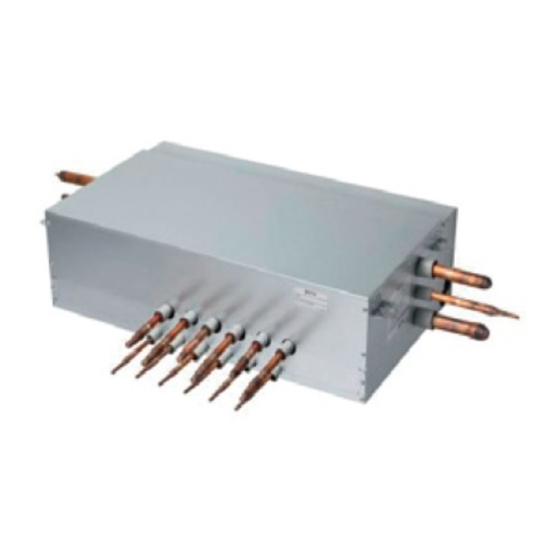
- Page 39 Setting For Heat Recovery Unit (Refer Only Heat DIP switch No. 3 Recovery Installation) Comm. Speed 1200 bps 9600 bps [Heat Recovery (HR) Unit Board] ARWM***CAS5 3 Series DIP switch Branch No. 7-Segment Reset button Main PCB (2EA, same P/No) Branch #1~4 Branch #5~8 Bypass...
- Page 40 Main function of SW02E ON S/W Selection No.1 Method for pipe detection of an HR Unit (Auto/Manual) No.2 PRHR063A PRHR083A No.3 No. of connected branches 1 branch No.4 Connected No.5 Master/Slave (Main PCB) Setting No.6 EEPROM factory initialization (4,5,6) 2 branch Use only in factory production Connected No.7...
- Page 41 SW01C (Rotary S/W for addressing HR unit) Must be set to '0' when installing only one HR unit. When installing multiple HR units, address the HR units with sequentially increasing numbers starting from '0'. Maximum 16 HR Units can be installed. Ex) Installation of 3 HR units * Master Only * Master Only...
- Page 42 Automatic Addressing Normal setting (Non-Zoning setting) The address of indoor units would be set by Automatic ex) Manual pipe detection of Valve #1, 6. Addressing Master Master Master - Wait for 3 minutes after supplying power. (Master and Slave outdoor units, indoor units) - Press RED button of the outdoor units for 5 seconds.
- Page 43 WARNING The Procedure of Automatic Addressing • Execute auto addressing and auto pipe detection again whenever Power On the indoor PCB and HR unit PCB is replaced. - Operation error occurs unless power is supplied to the indoor Waiting 3 minutes and HR units.
- Page 44 Flow chart of auto pipe detection Process Confirm indoor unit’s address setting Is the number Turn No.1 of DIP s/w SW02M of HR unit PCB off. of indoor units connected and displayed one equal? Pipe detection error occurs for 30 Confirm that the setting of No.2, 3 of seconds.
- Page 45 Flow chart of manual addressing for pipe Example of manual valve addressing (Non-Zoning detection setting) (In case that an indoor unit of central control address "11" is connected Execute in case of Auto pipe detection to a valve #1 of an HR unit) failure - Prerequisite for manual valve addressing: central control address of each indoor unit must be preset differently at its wired remote...
- Page 46 Example of manual valve addressing (Zoning Example of checking valve address setting) (In case that an indoor unit of central control address "11" is connected to a valve #1 of an HR unit) (In case that an indoor unit of central control address "11" is connected to a valve #1 of an HR unit) Display and setup Setup and Contents...
- Page 47 Mode Function Option Value Action Group recognizing the central controller Remarks Content Display1 Content Display2 Content Display3 Content Display4 Implement Display5 No.0 group (00~0F) Cool & Heat Selected oFF op1~op2 No.1 group (10~1F) Selector the option Outdoor unit Set the No.2 group (20~2F) 0~254 address...
- Page 48 CAUTION Right side Left side • Ask an authorized technician to setting a function. Switch (Up) Switch (Down) Target pressure adjusting (Fn 8) How to set the mode Turn on DIP switch No.5 of the master unit PCB CAUTION • Ask an authorized technician to setting a function. Use ‘▶‘...
- Page 49 Function setting Compressor Input Current Limit Mode Compressor Input Current Limit Setting Frequency (Hz) 100 % 95 % 143 Hz 90 % 135 Hz 85 % 128 Hz 80 % 120 Hz 75 % 113 Hz 70 % 105 Hz 65 % 98 Hz 60 %...
-
Page 50: Test Run
Sol. Valve 220 V output (Fn 41) TEST RUN It is the function to select 220 V output when you want solenoid valve Precaution before test run control. How to set the mode Check whether the air is completely removed and the water supply is flowing smoothly. - Page 51 Water supply system test run How to Cope with Abnormal Test Run Before executing the test run for the product, you must first test the heat source water system. Item Phenomenon Cause Checkpoint and resolution The test run for the product must be executed after checking the flow Check whether the heat source water rate and temperature of the heat source water supplied.
- Page 52 Maintenance of plate type heat exchanger Daily check/management Water quality control The plate type heat exchanger is not structured to be disassembled, As the scales are created in the panel heat exchanger, its efficiency cleaned or replaced with parts. To prevent corrosion or scaling on may decrease or damage may occur due to winter-sowing due to the the plate type heat exchanger, special care must be taken to control decrease in its flow.
- Page 53 Self-Diagnosis Function Error Indicator - This function indicates types of failure in self-diagnosis and occurrence of failure for air condition. - Error mark is displayed on display window of indoor units and wired remote controller, and 7-segment LED of outdoor unit control board as shown in the table.
- Page 54 Display Title Cause of Error Master Outdoor Unit Inverter Compressor Start The first start failure by Master Outdoor Unit Inverter Compressor Failure abnormality or Compressor locked Master outdoor unit inverter DC link over-voltage Compressor turned Off due to master outdoor unit inverter DC error voltage over-charge Master Outdoor Unit Inverter Compressor Over...
-
Page 55: Caution For Refrigerant Leak
Display Title Cause of Error Searching pipe Error Failure of automatic addressing of valves 1 #HR + h HR unit1 Liqiud sensor error Liquid pipe sensor of HR unit open or short 2 #HR + h HR unit1 Sub Cooling Pipe sensor error Sub Cooling Pipe In sensor of HR unit open or short 3 #HR + h HR unit1 Sub Cooling Pipe Out sensor error Sub Cooling Pipe Out sensor of HR unit. -
Page 56: Cooling Tower Applied Method
In case the concentration exceeds the limit When the concentration exceeds the limit, change original plan or take one of the countermeasures shown below: Closed type • Countermeasure 1 cooling tower Provide opening for ventilation. Provide 0.15 % or more opening to floor space both above and below door, or provide opening without door. - Page 57 Please call the installing contractor of your product, as warranty service will be provided by them. Service call Number # : (888) LG Canada, (888) 542-2623 CANADA Numéro pour les appels de service : LG Canada, 1-888-542-2623...