
Related Manuals for Sony BKS-R6010


Summary of Contents for Sony BKS-R6010
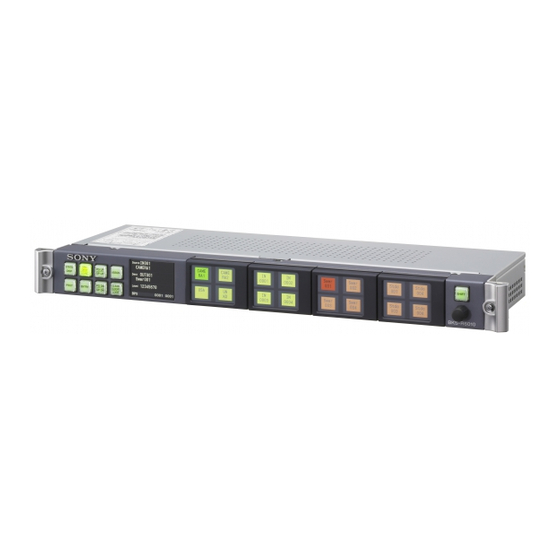
- Page 1 UNIVERSAL LCD REMOTE PANEL BKS-R6010 INSTALLATION MANUAL 1st Edition (Revised 2) Serial No. 10001 and Higher...
- Page 2 électrique, d’incendie ou de blessure n’effectuer que les réparations indiquées dans le mode d’emploi à moins d’être qualifié pour en effectuer d’autres. Pour toute réparation faire appel à une personne compétente uniquement. BKS-R6010 IM...
- Page 3 Rear: 10 cm (4 inches) or more For safety, do not connect the connector for peripheral device wiring that might have excessive voltage to the following port(s). : NETWORK connector Follow the instructions for the above port(s). 1 (P) BKS-R6010 IM...
- Page 5 2-2-1. BKS-R6010 (V1.00 - V1.01) ........ 2-2 Trademarks ................... 4 2-2-2. BKS-R6010 (Ver. 2.00 or higher) ......2-3 2-3. User Default <BKS-R6010 (Ver. 2.00 or higher)> ..2-7 1. Installation 2-4. Periodic Inspection ............2-9 2-5. Lithium Battery ............... 2-9 1-1.
- Page 7 Manual Structure Purpose of this manual This manual is the installation manual of Universal LCD Remote Panel BKS-R6010. This manual is intended for use by trained system and service engineers, and deicribes the information on installing the BKS-R6010. Related manuals Besides this Installation Manual, the following manuals are prepared for the BKS- R6010.
- Page 8 Trademarks and registered trademarks used in this manual are follows. . Ethernet is a registered trademark of Xerox Corporation. . IBM and AT are registered trademarks of International Business Machines Corporation. . Windows is a registered trademark of Microsoft Corporation. BKS-R6010 IM...
- Page 9 Rack Mounting Connection 1-7. Matching Connectors 1-8. Input and Output Signals of Connectors 1-12. System Connection Initial setting 1 1-13. Setup Menu at Startup 1-14. Setting Network Connection (IP Address) Initial setting 2 System Setup Manual Operation check BKS-R6010 IM...
- Page 10 Select an installation place as operating temperature of the If you have questions on the use of the above Power Cord/ unit is 5 dC to 40 dC. Do not place the unit near heart Appliance Connector/Plug, please contact your local Sony sources. Sales Office/Service Center.
- Page 11 1-4. Installation Space Unit : mm BKS-R6010 IM...
- Page 12 1-6. For Use in an OB Van To install the unit into a rack, have the four binding-head When the BKS-R6010 is to be used in an OB van, be sure screws (+B5 x 10) ready. to band the cables to a rack strut to avoid having the Secure the front panel of the unit to the rack with the screws.
- Page 13 RS232C : RS-232C (D-sub 9-pin, Male) _ EXT VIEW _ Pin No. Signal name Input/Output Function No connection Received data Transmitted data Data terminal ready Signal ground Date set ready Request to send Clear to send No connection BKS-R6010 IM...
- Page 14 Lights when the +12 V-1 power is supplied normally. D808 (A-1): CONFIG For DEBUG. It turns off for normal operation. D809 (E-1): 12 V-2 +12 V-2 power supply status indication. Lights when the +12 V-2 power is supplied normally. BKS-R6010 IM...
- Page 15 D402 (B-1): BOOT For DEBUG. It turns off for normal operation. D403 (B-1): CPU CPU-417 board CPU status indication. Blinks several times in 1 second while CPU is operating. D404 (B-1): APL For DEBUG. It turns off for normal operation. BKS-R6010 IM...
- Page 16 2. Remove the internal cap by holding the grooves of the internal cap in the removed button with the tips of the tool and slightly bending the internal cap. 3. Attach a key label and install the internal cap. 4. Install the button in the original location. BKS-R6010 IM...
- Page 17 2. Use the screwdriver as a lever to unhook the tab. 3. Press down on the top of the touch plate to snap the other two tabs into place. 3. Gently unhook the other tab with the same method. Tabs 4. Remove the touch plate. BKS-R6010 IM...
- Page 18 * : (P) and (S) indicate the setting of the S/P selector switch on the CPU board (on the CA board for the IXS series) in the routing switcher. Switchers other than the IXS-6700/IXS-6600 can be also set as a primary station. In this case, some functions are limited. 1-10 BKS-R6010 IM...
- Page 19 *2 : Install the 75 Z terminators to the T type bridge of the last device on the S-BUS data link and to the unused REMOTE 1 connector *3: The remote control panel BKS-R6010 (Ver. 2.10 or higher) can be used as a subnet controller. To connect to the third-level station, use the REMOTE1B connecter.
- Page 20 . In the secondary controller and routing switcher, only one REMOTE 1 connector can be used each. How to use the Y-type bridge The Y-type bridge is supplied with the BKS-R6010. Use the Y-type bridge as follows. REMOTE1 (BNC-type connector, male)
- Page 21 422A), it is converted to the S-BUS command, which can change the cross-points of the routing switchers in the S-BUS control system. The BKS-R6010 returns the cross-point status of the S-BUS in response to the inquiry from the host controller.
- Page 22 (Ethernet) connection. For example, if BZR-21 (remote control panel GUI) is installed to the computer, the cross-point can be switched via Ethernet and the result of the switching is applied to the routing switcher control unit (remote control panel) connected with S-BUS and to the BKS-R6010 connected to the network (Ethernet).
- Page 23 Crossover cable : 75 Z terminator As shown in the diagram, the BKS-R6010 can be connected to the switcher system of the MVS-8000 series as an AUX panel. The settings of the BKS-R6010 remote control panel and the IXS-6700/6600 routing switcher can be set using a Web browser from the Windows PC on which the BZR-26 (PC Web Server for Routing Switcher System) is installed and connected via Ethernet.
- Page 24 When the four buttons of the LCD button unit are pressed simultaneously at the reset, the system setup menu is displayed on the LCD status indicator where the basic settings for BKS-R6010 can be configured. Operation flow chart when the multiple buttons are pressed simultaneously is shown below.
- Page 25 BACK SPACE. Cancels the one character only that is entered immediately. EXIT TOP MENU Setting item Selecting item Selecting item CANCEL LEVEL1 MENU CANCEL EXIT Setting entry Setting item To normal startup Fig. Flow chart of button operations 1-17 BKS-R6010 IM...
- Page 26 1) SET S-BUS ID 2)NO 2) SET BAUD RATE . STATION ID setting screen TOP MENU → 1) SET S-BUS MODE → 1) SET S-BUS ID SYSTEM SETUP MENU SET S-BUS MODE SET S-BUS ID STATION NUM.? (2-254) 1-18 BKS-R6010 IM...
- Page 27 Menu to operate the factory default settings FACTORY RESET READY? Resets the machine settings to the factory default setting. 1) YES 1) Resets the machine settings to the factory default setting. 2) NO 2) Moves to the top menu without resetting. 1-19 BKS-R6010 IM...
- Page 28 When four of the LCD button units are pressed simultaneously at reset, the system setup menu is displayed on the LCD status indicator where the basic settings for the BKS-R6010 can be configured. The following chart shows the operations when multiple buttons are pressed simultaneously.
- Page 29 Cancels the entry. Returns to the layer one level higher than the current layer of the menu. Cancels one character of the latest entry. Rotary knob Selects the option as the number selection button does. (ROTATE) Rotary knob Same as the ENTER button (PUSH) 1-21 BKS-R6010 IM...
- Page 30 Detailed System setup (2/2) MAINTENANCE MODE Maintenance menu Detailed System setup (2/2) NETWORK SETUP Setting menu regarding Network (Ver. 2.10 or higher) *: The detailed system setup menu has the shaded items added to the system setup menu. 1-22 BKS-R6010 IM...
- Page 31 BLOCK 2 Comment of the Sets the user default for block 3 BLOCK 3 Comment of the Sets the user default for block 4 BLOCK 4 Comment of the Sets the user default for block 5 BLOCK 5 1-23 BKS-R6010 IM...
- Page 32 Specifies the switcher TALLY group to be displayed. *1 : For details, refer to the System Setup Manual. *2 : For details, refer to “4. Panel assignment information of the BUTTON ASSIGN Initialization operations” on Page 1-35. 1-24 BKS-R6010 IM...
- Page 33 1 STAND ALONE Mother/Daughter settings 2 MOTHER . DAUGHTER 5 SUBNET MODE 1 DISABLE Setting on the subnet controller (Ver.2.10 or higher) 2 ENABLE function. 3 AUTO *1 : For details, refer to the System Setup Manual. 1-25 BKS-R6010 IM...
- Page 34 Enter IP address IP address setting of the TRAP2 send (12 digits fixed length) destination. *1 : For details, refer to the System Setup Manual. *2 : For details, refer to “1-14. Setting Network Connection (IP Address)”. 1-26 BKS-R6010 IM...
- Page 35 . Detailed system setup menu mode 2/2 SYSTEM SETUP MENU 1)MAINTENANCE MODE Moves to the maintenance menu Moves to the network setting menu (Ver.2.10 or higher) 2)NETWORK SETUP Moves (Returns) to the previous page PG-DN 1-27 BKS-R6010 IM...
- Page 36 Display example SYSTEM SETUP MENU RECALL USER DEF. . SET Bch BAUD RATE setting screen BLOCK #1 READY? Display example (Ver. 2.10 or higher) 1)YES 2)NO SYSTEM SETUP MENU SET S-BUS MODE Bch BAUD RATE 1)312kbps 2)1250kbps 1-28 BKS-R6010 IM...
- Page 37 BUTTON ASSIGN initialization operations” DSCRPT PRIORITY described later. . ILLUMI. LEVEL setting screen #1 = 7 Display example SYSTEM SETUP MENU SET DISP. MODES ILLUMI. LEVEL 0:DSCRPT 1-7:ALIAS Enter a decimal 1 digit (0 to 7) ILLUMINATION LEVEL? 1-29 BKS-R6010 IM...
- Page 38 . SET DISP. MODES setting screen (4/4) the corresponding TALLY GROUP turns ON/ OFF (OFF display: “_”). Display example 2. Push ENTER or the rotary knob to confirm SYSTEM SETUP MENU TALLY GROUP. SET DISP. MODES 1)CHRA. ENCODE PG-DN 1-30 BKS-R6010 IM...
- Page 39 Enter a decimal 1 digit (0 to 7) PG-DN PG-UP . SET PANEL STATUS setting screen (3/5) Display example SYSTEM SETUP MENU SET PANEL STATUS 1)PRESET MODE 2)PANEL FUNCTION 3)ROTARY PUSH 4)PANEL MODE 5)SUBNET MODE Ver. 2.10 or higher PG-DN PG-UP 1-31 BKS-R6010 IM...
- Page 40 SET DISP. MODES PAGE GROUP PAGE9-16 12345678 1. Each time the selection button 1 to 7 is pressed, the corresponding PAGE GROUP turns ON/OFF (OFF display: “_”). 2. Push ENTER or the rotary knob to confirm PAGE GROUP. 1-32 BKS-R6010 IM...
- Page 41 Display example the date. SYSTEM SETUP MENU MAINTENANCE MODE SET/RESET STATUS 1)PSU ELAPSED TIME 2)SET CLOCK . PSU ELAPSDE TIME reset screen Display example SYSTEM SETUP MENU MAINTENANCE MODE SET/RESET STATUS PSU ELAPSED TIME RESET READY? 1)YES 2)NO 1-33 BKS-R6010 IM...
- Page 42 . TERM PORT entry screen Display example 2)OPT PORT2 3)OPT PORT3 SYSTEM SETUP MENU NETWORK SETUP TERM PORT PG-DN PG-UP TERM PORT . NETWORK SETUP setting screen (4/4) Display example 1001 SYSTEM SETUP MENU NETWORK SETUP 1)SNMP TRAP1 2)SNMP TRAP2 PG-DN 1-34 BKS-R6010 IM...
- Page 43 (3) Button assignment when U-SRC L-DEST is selected The upper half of the selection buttons are assigned to the source selection buttons and the lower half are assigned to the destination selection buttons. 1-35 BKS-R6010 IM...
- Page 44 1. Copy all files contained in the distributed package to a blank CD-R disc or in a temporary directory (for example C:¥TEMP). 2. Run the SETUP.EXE and install the BZR-25 in accordance with the instructions displayed on the Install screen. Upon completion of installation, the distributed file is no more necessary. Delete it later. 1-36 BKS-R6010 IM...
- Page 45 2) Click Setup of the menu bar to select Network ... or alternately click of the tool bar. Menu bar The Network Setup dialog window will be opened. Tool bar Set the parameters related to the network of the selected equipment. Equipment list 1-37 BKS-R6010 IM...
- Page 46 OPT Port3: Enter the port number (ROT16) to be used for communication between subnet controller and third level station. Enter the same value that has been set for the subnet controller. 1-38 BKS-R6010 IM...
- Page 47 When the setting is complete, the Information Setup window is closed. 10. When the setting is complete, click File of the menu bar to exit the BZR-25. Refer to the online help of the BZR-25 for more details of the operating procedure. 1-39 BKS-R6010 IM...
- Page 48 4093 x 4093 controller BZR-IF830 (Device [a]). Island B consists of remote control group B-1, with three remote control BKS-R6010 units (Devices [b1] to [b3]), and remote control group B-2, with two remote control BKS-R6010 units (Devices [b4] and [b5]).
- Page 49 DELEGATE denotes the state where the remote control panel is directly linked with the primary station, whereas CLIENT denotes the state where the remote control panel communicates with the primary station via a DELEGATE unit without being directly linked with the primary station. 1-41 BKS-R6010 IM...
- Page 50 Device[a] BZR-IF830 4kx4k controller Device[b] IXS-6700 Primary station Island B Device[b1] BKS-R6010 Secondary station Remote control Device[b2] BKS-R6010 Secondary station group B-1 Device[b3] BKS-R6010 Secondary station Device[b4] BKS-R6010 Secondary station...
- Page 51 Secondary station 192.168.0.25 Device[b5] BKS-R6010 Secondary station 192.168.0.26 Device[c] IXS-6700 Primary station 192.168.0.30 Device[c1] BKS-R6010 Secondary station 192.168.0.32 Device[c2] BKS-R6010 Secondary station 192.168.0.33 Device[c3] BKS-R6010 Secondary station 192.168.0.34 Device[c4] BKS-R6010 Secondary station 192.168.0.35 Device[c5] BKS-R6010 Secondary station 192.168.0.36 1-43 BKS-R6010 IM...
- Page 52 OPT IP1. Also, specify the Port number used to communicate between the primary and secondary stations. Set the IP address for the connected primary station here. Set the same value as the connected primary station here. Example BZR-25 Setting Screen for BKS-R6010 (Device [b1]) 1-44 BKS-R6010 IM...
- Page 53 192.168.0.30 8005 Device[c1] BKS-R6010 Secondary station 192.168.0.32 192.168.0.30 8005 Device[c2] BKS-R6010 Secondary station 192.168.0.33 192.168.0.30 8005 Device[c3] BKS-R6010 Secondary station 192.168.0.34 192.168.0.30 8005 Device[c4] BKS-R6010 Secondary station 192.168.0.35 192.168.0.30 8005 Device[c5] BKS-R6010 Secondary station 192.168.0.36 192.168.0.30 8005 1-45 BKS-R6010 IM...
- Page 54 (2) Set the remote control group for each remote controller (BKS-R6010). As shown in Table 1, each remote controller (BKS-R6010) is sorted into groups and settings are made for each group. Set a different IP address for OPT IP2 in each group (set the same value within the same group).
- Page 55 1-47 BKS-R6010 IM...
- Page 56 1-16. Subnet Functions <BKS-R6010 (V2.10 or higher)> 1-16-1. Outline The BKS-R6010 (V2.10 or higher) has the S-BUS subnet controller function, and is capable of forming an S-BUS subnet. 1. Features The S-BUS subnet controller enables you to increase the number of units to be controlled in an S-BUS network and at the same time to reduce the response time by decreasing the apparent number of units to be controlled from the primary station.
- Page 57 REMOTE1 A Routing switcher remote panel max. 253 unit Routing switcher Routing switcher remote panel Routing switcher remote panel Routing switcher remote panel *1 : Operates as a secondary station remote panel. *2 : BKS-R6010 (V2.10 or higher) 1-49 BKS-R6010 IM...
- Page 58 Settings for the third-level units are made from a control terminal connected via the NETWORK connector of the S-BUS subnet controller of BKS-R6010 (V2.10 or higher) on the secondary station. The NETWORK connector of the S-BUS subnet controller (secondary station) can back up and restore the setting data of the third-level station using the BZR-20.
- Page 59 Function (S-BUS subnet controller) When the subnet function of the BKS-R6010 (Ver. 2.10 or higher) is activated, the BKS-R6010 (Ver. 2.10 or higher) functions as the secondary station. The REMOTE1 A connector is for the connection with the primary station, and the REMOTE1 B connector is for the connection with the third-level stations.
- Page 60 . Control terminal for setup of the third-level station . Backup and restore of the third-level station’s setup data using BZR-20 . Download of program (The downloaded program is written in the flash memory.) 1-52 BKS-R6010 IM...
- Page 61 <BKS-R6010 (Ver.2.00 or higher)> The standard time for each operation is as follows. Trans Writing to Restarting Total The BKS-R6010 of ver. 2.00 or higher supports the ferring the flash multilingual display. Make sure that the font data corre- data memory...
- Page 62 5. Check that the type and version are the same as those of the downloaded font data. For details about the display items, refer to “V : DISPLAY UNIT STATUS” in “2-4. Setting Items of the Secondary Station (BKS-R6010)” of the System Setup Manual SONY ROUTING SYSTEM SETUP MENU BKS-R6010 V2.10...
- Page 63 *1 : The “Communication Error” is continuously displayed until the normal communication state is resumed. *2 : The icon continues to be displayed in red until the normal communication state is resumed. This is supported by V2.10 or higher. BKS-R6010 IM...
- Page 64 2-2. Checking Equipment Status 2-2-1. BKS-R6010 (V1.00 - V1.01) If any operation from the panel is attempted while the panel is set in the LOCK state (on-panel operation is prohibited), the UNIT ID display screen indicating the station number and other information is displayed on the LCD status display window.
- Page 65 2-2-2. BKS-R6010 (Ver. 2.00 or higher) If any operation from the panel is attempted while the panel is set to the LOCK state (on-panel operation is prohibited), the UNIT ID display screen showing the station number and other information is displayed on the LCD status display window.
- Page 66 Displays the total operation time of the power supply unit. When the time exceeds 50,000 hours, it is highlighted in red. STATUS LOG Status message number/total number of messages Message Displays the received S-BUS message. Displays one status in one screen. BKS-R6010 IM...
- Page 67 DISABLE: The subnet controller is disabled. When the subnet function is enabled and the S-BUS Bch is disconnected, "S-BUS-B ERR" is displayed in red. *1 : For details about CLIENT,DELEGATE, refer to the setting example in "1-15. Network Connection". BKS-R6010 IM...
- Page 68 Displays the same terminal menu items of the subnet as those displayed in “W : SYSTEM STATUS LOG”. Displays 64 status messages at most. Displays one status message in one screen. Function buttons [PG-UP] button: Displays the next statement. [PG-DN] button: Displays the previous statement. BKS-R6010 IM...
- Page 69 The saving screen (SAVE CURRENT TABLE) of the user default is displayed. . Display example BKS-R6010 (Ver. 2.00 or higher) has five storage areas for user settings (user default) so that all setting information of Screen 1 (Page 1) the operation status of the current panel can be saved in the SAVE CURRENT TABLE user storage areas.
- Page 70 4. System setup menu appears. 5. Select “3) RECALL USER DEF.”. 6. Select the user setting to call by referring to the comment (the date and time when the setting is saved). 7. Press the [EXIT] button to exit the menu. BKS-R6010 IM...
- Page 71 Replacement time with BZR-20 V3.0 or higher and a web browser R6010 *1: BKS-R6010 is supported from V2.0 or higher. Also, a web browser can The battery has not Before the non-powered period only be used when IXS-6600/IXS-6700 V2.2 or higher is used as a...
- Page 74 Sony Corporation BKS-R6010 (SY) E 2008. 8 16 9-968-372-03 ©2007...