
Related Manuals for Asus RS500A-E10 Series


Summary of Contents for Asus RS500A-E10 Series
- Page 1 RS500A-E10 Series RS500A-E10-PS4 RS500A-E10-RS4 RS500A-E10-RS12U 1U Rackmount Server User Guide...
- Page 2 ASUSTeK COMPUTER INC. (“ASUS”). ASUS provides this manual “as is” without warranty of any kind, either express or implied, including but not limited to the implied warranties or conditions of merchantability or fitness for a particular purpose. In no...
-
Page 3: Table Of Contents
Expansion slot ..................2-15 2.5.1 Installing an expansion card to the riser card bracket ....2-15 2.5.2 Installing an ASUS PIKE II card ..........2-17 2.5.3 Replacing the ASUS PCIE-NVME2-OCuLink card to the butterfly riser card bracket (for RS500A-E10-RS12U only)..2-20 2.5.4... - Page 4 Onboard LEDs .................... 4-8 Internal connectors .................. 4-11 Chapter 5: BIOS Setup Managing and updating your BIOS ............5-2 5.1.1 ASUS CrashFree BIOS 3 utility........... 5-2 5.1.2 ASUS EZ Flash Utility ..............5-3 5.1.3 BUPDATER utility ............... 5-4 BIOS setup program .................. 5-6 5.2.1...
- Page 5 Contents Advanced menu ..................5-10 5.4.1 Trusted Computing..............5-11 5.4.2 PSP Firmware Versions ............5-11 5.4.3 APM Configuration ..............5-12 5.4.4 Onboard LAN Configuration ............5-13 5.4.5 Serial Port Console Redirection ..........5-14 5.4.6 CPU Configuration ..............5-17 5.4.7 PCI Subsystem Settings ............5-17 5.4.8 USB Configuration ..............
- Page 6 Chapter 6: Driver Installation Running the Support DVD ................. 6-2 Appendix KRPA-U16 block diagram ..................A-2 Notices ........................A-4 REACH ....................A-5 Australia statement notice ................A-5 ASUS contact information ..................A-6...
-
Page 7: Safety Information
Safety information Electrical Safety • Before installing or removing signal cables, ensure that the power cables for the system unit and all attached devices are unplugged. • To prevent electrical shock hazard, disconnect the power cable from the electrical outlet before relocating the system. -
Page 8: About This Guide
About this guide Audience This user guide is intended for system integrators, and experienced users with at least basic knowledge of configuring a server. Contents This guide contains the following parts: Chapter 1: Product Introduction This chapter describes the general features of the server, including sections on front panel and rear panel specifications. - Page 9 Refer to the following sources for additional information, and for product and software updates. ASUS Control Center (ACC) user guide This manual tells how to set up and use the proprietary ASUS server management utility. ASUS websites The ASUS websites worldwide provide updated information for all ASUS hardware and...
-
Page 11: Chapter 1: Product Introduction
Chapter 1: Product Introduction Product Introduction This chapter describes the general features of the chassis kit. It includes sections on front panel and rear panel specifications. -
Page 12: System Package Contents
System package contents Check your system package for the following items. Model Name RS500A-E10-PS4, RS500A-E10-RS4, RS500A-E10-RS12U Chassis ASUS R10E 1U Rackmount Chassis Motherboard ASUS KRPA-U16/SYS Server Board 1 x 650W Single Power Supply (RS500A-E10-PS4) 1 x 1+1 650W Redundant Power Supply (RS500A-E10-RS4, RS500A-E10-RS12U) 4 x Hot-swap 3.5-inch or 2.5-inch Storage Device Trays... -
Page 13: Serial Number Label
Serial number label Before requesting support from the ASUS Technical Support team, you must take note of the product’s serial number containing 12 characters such as xxS0xxxxxxxx shown as the figure below. With the correct serial number of the product, ASUS Technical Support team members can then offer a quicker and satisfying solution to your problems. -
Page 14: System Specifications
System specifications The ASUS RS500A-E10 Series is a 1U barebone server system featuring the ASUS KRPA-U16/SYS Server Board. The server supports AMD EPYC™ 7002 Series Rome processors plus other latest technologies through the chipsets onboard. RS500A-E10-PS4 RS500A-E10-RS4 RS500A-E10-RS12U Model Name... - Page 15 OCP LAN) - 4 x LAN LED (LED1~2 for on-board LAN, - 1 x Location LED 3~4 for OCP LAN) OS Support Please find the latest OS support from http://www.asus.com/ ASUS Control Center Software Management Out of Band Solution...
- Page 16 RS500A-E10-PS4 RS500A-E10-RS4 RS500A-E10-RS12U Model Name Single 650W 80 PLUS 1+1 Redundant 650W 80 PLUS Platinum Power Supply Platinum Power Supply Power Supply (following different Rating: Rating: 100~127/200~240 Vac, 10A/5A, 100~127/200~240Vac, configuration by region) 50~60Hz, Class I 9A/5A, 50~60Hz, Class I Operating temperature: 10°C –...
-
Page 17: Front Panel Features
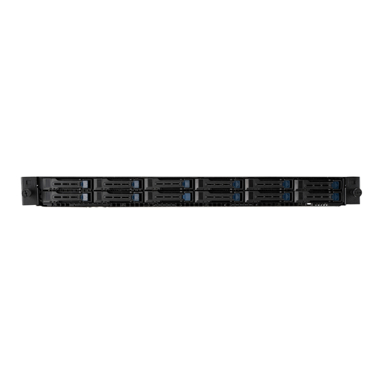
Bay 1 Bay 3 Bay 5 Bay 7 Bay 9 Bay 11 Rack screw Bay 2 Bay 4 Bay 6 Bay 8 Power button Power LED Asset tag Message LED LAN 1 LED Location LED LAN 2 LED ASUS RS500A-E10 Series... -
Page 18: Rear Panel Features
PCI-E slot Locate LED Redundant power supply LAN port for iKVM* COM port OCP 2.0 Mezzanine slot Power button *This port is for ASUS ASMB9-iKVM controller card only. RS500A-E10-PS4 Q-Code LED Power cord connector PCI-E slot Locate LED and power supply... -
Page 19: Internal Features
The barebone server does not include a floppy disk drive. Connect a USB floppy disk drive to any of the USB ports on the front or rear panel if you need to use a floppy disk. WARNING HAZARDOUS MOVING PARTS KEEP FINGERS AND OTHER BODY PARTS AWAY ASUS RS500A-E10 Series... - Page 20 RS500A-E10-RS12U Power supply and power fan Riser card (Gen4 x16/x8 link) ASUS KRPA-U16/SYS Server Board System fans SATA/SAS/NVMe backplane (hidden) 12 x 2.5” storage device bays Front I/O boards Asset tag (hidden) ASUS PCIE-NVME4-OCuLink card ASUS PCIE-NVME2-OCuLink card Turn off the system power and detach the power supply before removing or replacing any system component.
-
Page 21: Led Information
A hardware monitor event is indicated Function off Location switch is pressed Location button with LED (Press the location switch again to turn off) No LAN connection LAN LEDs Blinking LAN is transmitting or receiving data LAN connection is present ASUS RS500A-E10 Series 1-11... -
Page 22: Lan (Rj-45) Leds
1.7.2 LAN (RJ-45) LEDs LAN port LED indications ACT/LINK SPEED Activity/Link LED Speed LED Status Description Status Description No link 10 Mbps connection GREEN Linked ORANGE 100 Mbps connection BLINKING Data activity GREEN 1 Gbps connection LAN port Dedicated Management LAN port (DM_LAN1) LED indications ACT/LINK SPEED Activity/Link LED... -
Page 23: Q-Code Table
Insufficient space for secure OS (range of free SRAM to SVC stack base) 0x37 Error SYSHUB mapping memory target type is not supported 0x38 Error Attempt to unmap permanently mapped TLB to PSP secure region (continued on the next page) ASUS RS500A-E10 Series 1-13... - Page 24 Action PHASE POST CODE TYPE DESCRIPTION 0x39 Error Unable to map an SMN address to AXI space 0x3A Error Unable to map a SYSHUB address to AXI space 0x3B Error The count of CCXs or cores provided by bootrom is not consistent 0x3C Error Uncompressed image size doesn't match value in compressed header...
- Page 25 Progress Enter recovery mode due to trustlet validation fail. 0xD8 Progress Enter recovery mode due to OS validation fail. 0xD9 Progress Enter recovery mode due to OEM public key not found. (continued on the next page) ASUS RS500A-E10 Series 1-15...
- Page 26 Action PHASE POST CODE TYPE DESCRIPTION 0x10 Progress PEI Core Entry 0x11 Progress PEI cache as ram CPU initial PEI(Pre-EFI Initialization) phase 0x15 Progress NB Initialization before installed memory 0x19 Progress SB Initialization before installed memory 0x32 Progress CPU POST-Memory Initialization 0x33 Progress CPU Cache Initialization...
-
Page 27: Chapter 2: Hardware Information
Chapter 2: Hardware Information Hardware Information This chapter lists the hardware setup procedures that you have to perform when installing or removing system components. -
Page 28: Chassis Cover
Chassis cover Removing the rear cover Locate and remove the front side screws. Front side screw Loosen the two thumbscrews on the rear panel to release the rear cover from the chassis. Thumbscrews Firmly hold the cover and slide it toward the rear panel for about half an inch until it is disengaged from the chassis. -
Page 29: Central Processing Unit (Cpu)
Contact your retailer immediately if the PnP cap is missing, or if you see any damage to the PnP cap/socket contacts/motherboard components. ASUS will shoulder the cost of repair only if the damage is shipment/ transit-related. - Page 30 Loosen each screw one by one in the sequence shown on the socket to open the load plate. Slightly lift open the rail frame. Load plate Rail frame External cap Slide the external cap out of the rail frame. External cap Rail frame PnP cap Chapter 2: Hardware Information...
- Page 31 CPU, then secure each screw one by one in the sequence shown on the socket to completely secure the load plate. The load plate screws are T20 models. A torque value of 12 inch-lbf is recommended. ASUS RS500A-E10 Series...
- Page 32 Twist each of the four screws with a screwdriver just enough to attach the heatsink to the motherboard. When the four screws are attached, tighten them one by one in a diagonal sequence to complete the installation. The heatsink screws are T20 models. A torque value of 12 inch-lbf is recommended. Chapter 2: Hardware Information...
-
Page 33: System Memory
12 DIMMs 14 DIMMs 16 DIMMs • Always install DIMMs with the same CAS latency. For optimum compatibility, it is recommended that you obtain memory modules from the same vendor. • Start installing the DIMMs in slots A2. ASUS RS500A-E10 Series... -
Page 34: Installing A Dimm On A Single Clip Dimm Socket
2.3.3 Installing a DIMM on a single clip DIMM socket Ensure to unplug the power supply before adding or removing DIMMs or other system components. Failure to do so may cause severe damage to both the motherboard and the components. Unlock a DIMM socket by pressing the DIMM notch retaining clip outward. -
Page 35: Storage Device
The system supports four hot-swap SATA/SAS storage devices. The storage device installed on the storage device tray connects to the motherboard SATA/SAS ports via the SATA/SAS backplane (SAS drives require an optional ASUS PIKE II card). To install a 3.5” hot-swap SATA/SAS storage device: Push the spring lock to the right (A) then pull the tray lever outward (B) to release the storage device tray. - Page 36 Place the 3.5” SATA/SAS storage device into the tray then secure it with four screws. Insert the storage device tray and storage device assembly all the way into the depth of the bay until just a small fraction of the tray edge protrudes. When installed, the SATA/SAS connector on the drive connects to the SATA/SAS interface on the backplane.
- Page 37 Tray lever Spring lock Firmly hold the tray lever and pull the tray out of the bay. Place the tray on a flat and stable surface. Prepare the 2.5” storage device and the bundled set of screws. ASUS RS500A-E10 Series 2-11...
- Page 38 Place the 2.5” storage device into the tray then secure it with four screws. Insert the tray and storage device assembly all the way into the depth of the bay until just a small fraction of the tray edge protrudes. When installed, the SATA/NVMe connector on the storage device connects to the SATA/ NVMe interface on the backplane.
- Page 39 The system supports twelve (12) 2.5” hot-swap SATA/SAS/NVMe storage devices. The storage device installed on the storage tray connects to the motherboard SATA/SAS/NVMe ports via the SATA/SAS/NVMe backplane (SAS drives require an optional ASUS PIKE II card). To install a 2.5” hot-swap SATA/SAS/NVMe storage device: Push the spring lock to the right (A) then pull the tray lever outward (B) to release the storage tray.
- Page 40 Place the SATA/SAS/NVMe storage device into the tray then secure it with four screws. Insert the storage tray and storage device assembly all the way into the depth of the bay until just a small fraction of the tray edge protrudes. When installed, the SATA/SAS/NVMe connector on the storage device connects to the SATA/SAS/NVMe interface on the backplane.
-
Page 41: Expansion Slot
Firmly hold the riser card bracket, then pull it up to detach it from the PCI Express slot on the motherboard. Place the riser card bracket on a flat and stable surface. Remove the screw from the metal bracket (A), then remove the metal bracket (B). ASUS RS500A-E10 Series 2-15... - Page 42 Insert the expansion card into the PCI-E slot. Ensure that the golden fingers are totally inserted into the slot, then secure the expansion card with the screw removed before. Install the riser card bracket and PCI Express card assembly back into the PCI Express slot on the motherboard.
-
Page 43: Installing An Asus Pike Ii Card
2.5.2 Installing an ASUS PIKE II card You can install an ASUS PIKE II card on the provided riser card bracket. To install an ASUS PIKE II card: Firmly hold the riser card bracket, then pull it up to detach it from the PCI Express slot on the motherboard. - Page 44 Insert the expansion card into the PCI-E slot. Ensure that the golden fingers are totally inserted into the slot, then secure the ASUS PIKE II card with the screw removed before. Remove the default mini-SAS HD cable from the motherboard.
- Page 45 Connect the mini-SAS HD cable to connector 1 of the ASUS PIKE II card. Connect to PIKE II connector 1 Reinstall the riser card bracket into the PCI Express slot on the motherboard. Ensure that the golden connectors of the riser card bracket is firmly seated in place.
-
Page 46: Replacing The Asus Pcie-Nvme2-Oculink Card To The Butterfly Riser Card Bracket (For Rs500A-E10-Rs12U Only)
(for RS500A-E10-RS12U only) The ASUS PCIE-NVME2-OCuLink card pre-installed on the butterfly riser card bracket on the PCIE2 slot supports NVME storage devices on Bay 11 and Bay 12. To replace the ASUS PCIE-NVME2-OCuLink card on the butterfly riser card bracket: Remove the OCuLink cables (right angle connectors) from its corresponding slots. - Page 47 Place the butterfly riser card bracket on a flat and stable surface. Remove the screw from the metal cover (A), then remove the ASUS PCIE-NVME2- OCuLink card (B) from the butterfly riser card bracket. Prepare the replacement ASUS PCIE-NVME2-OCuLink card.
- Page 48 Connect the OCuLink cables back into the corresponding slots to complete. OCuLink port 11 OCuLink port 12 2-22 Chapter 2: Hardware Information...
- Page 49 The ASUS PCIE-NVME4-OCuLink card pre-installed on the PCIE1 slot supports NVME storage devices on Bay 1 to Bay 4. To replace the ASUS PCIE-NVME4-OCuLink card: Remove the two (2) screws that secure the ASUS PCIE-NVME4-OCuLink card to the motherboard (A), then remove the ASUS PCIE-NVME4-OCuLink card from the motherboard (B).
- Page 50 Install the ASUS PCIE-NVME4-OCuLink card into the PCIE connector on the motherboard, ensure that the golden connectors is firmly seated in place (A). Secure the ASUS PCIE-NVME4-OCuLink card with the two (2) screws that you removed earlier to complete (B).
-
Page 51: Installing M.2 (Ngff) Cards
Locate the M.2 (NGFF) connector on your motherboard. Remove the top screw and the stand from the motherboard. Top screw Stand screw Select an appropriate screw hole on the motherboard for your M.2 card, then secure the stand to the motherboard. ASUS RS500A-E10 Series 2-25... - Page 52 Prepare the M.2 card. Align and insert the M.2 card into the M.2 connector on the motherboard. Ensure that the golden connector of the M.2 card is inserted firmly in place and that the screw hole on the M.2 card matches the stand screw on the motherboard.
-
Page 53: Installing Mezzanine Cards
Installing Mezzanine cards To install a Mezzanine card: Locate the Mezzanine card connector on your motherboard. Firmly hold the riser card bracket, then pull it up to detach it from the PCI Express slot on the motherboard. ASUS RS500A-E10 Series 2-27... - Page 54 Select the slots that are going to be used for your Mezzanine card, then use a screwdriver and pry the corresponding slots until it pops off. Prepare your Mezzanine card and the signal cable. Connect the signal transmission end (white) to the AUXLED_CON header on the card. AUXLED_CON1 Insert the ports of the Mezzanine card into the mounting hole on the chassis, then insert the golden connector of the Mezzanine card into the MEZZPCIE1 (OCP) connector on...
- Page 55 The two ends of the signal cable are different in size and color for easy recognition. Please refer to your exact cable. Reinstall the riser card bracket into the PCI Express slot on the motherboard. Ensure that the golden connectors of the riser card bracket is firmly seated in place. ASUS RS500A-E10 Series 2-29...
-
Page 56: Configuring An Expansion Card
2.5.7 Configuring an expansion card After installing the expansion card, configure the it by adjusting the software settings. Turn on the system and change the necessary BIOS settings, if any. See Chapter 5 for information on BIOS setup. Assign an IRQ to the card. Refer to the following tables. Install the software drivers for the expansion card. -
Page 57: Cable Connections
SATA connector (from motherboard to optional optical drive) System auxiliary panel connector (from motherboard to front I/O board) System panel connector (from motherboard to front I/O board) Mini-SAS HD connector (from motherboard to backplane) PSUSMB connector (from motherboard to power board) ASUS RS500A-E10 Series 2-31... - Page 58 RS500A-E10-RS12U Standard cables connected to the motherboard 24-pin ATX power connector (from power supply to motherboard) 8-pin 12V power connector (from power supply to motherboard) System fan connector (from system fan to motherboard) USB connector (from motherboard to front I/O board) SATA connector (from motherboard to backplane) System auxiliary panel connector (from motherboard to front I/O board) System panel connector (from motherboard to front I/O board)
-
Page 59: Sata/Sas Backplane Cabling
SATA/SAS backplane cabling RS500A-E10-RS4 / RS500A-E10-PS4 Connects to 8-pin plug Connects to the motherboard from power board Connect the SATA/SAS storage devices ASUS RS500A-E10 Series 2-33... - Page 60 RS500A-E10-RS12U Connects to the ASUS PCIE-NVME2-OCuLink Connects to the ASUS PCIE-NVME4- card for Bay 9 to Bay 12 OCuLink card for Bay 5 to Bay 8 Connects to the motherboard Connects to the motherboard Connects to the motherboard Connects to the motherboard...
-
Page 61: Optional Components
To uninstall the system fans, hold the system fan by the tabs and lift the fan out of the fan cage. To reinstall the system fans, insert the fan into the fan cage. Ensure the fan connector is seated firmly within the cable holder. ASUS RS500A-E10 Series 2-35... -
Page 62: Redundant Power Supply Module (For Rs500A-E10-Rs4 / Rs500A-E10-Rs12U Only)
2.8.2 Redundant power supply module (for RS500A-E10-RS4 / RS500A-E10-RS12U only) To replace a failed redundant power supply module: Lift up the power supply module lever. Module lever Hold the power supply module lever and press the PSU latch, then pull the power supply module out of the system chassis. -
Page 63: Replacing The Optical Drive (For Rs500A-E10-Rs4 / Rs500A-E10-Ps4 Only)
The storage device tray is correctly placed when its front edge aligns with the bay edge. Secure the optical drive with the screw that you removed in step 1. ASUS RS500A-E10 Series 2-37... - Page 64 2-38 Chapter 2: Hardware Information...
-
Page 65: Chapter 3: Installation Options
Chapter 3: Installation Options Installation Options This chapter describes how to install the optional components and devices into the barebone server. -
Page 66: Rail Kit Installation
Rail kit installation 3.1.1 Tool-less Friction Rail Kit The tool less design of the rail kit allows you to easily install the rack rails into the server rack without the need for additional tools. The kit also comes with a metal stopping bracket that can be installed to provide additional support and stability to the server. - Page 67 Select a desired space and place the appropriate rack rail (left and right) on opposite positions on the rack. A 1U space consists of three square mounting holes with two thin lips on the top and the bottom. ASUS RS500A-E10 Series...
- Page 68 Secure the rail components to the rail using the bundled screws. Press the spring lock ( ) then insert the studs into the selected square mounting holes on the rack post. Press the spring lock on the other end of rail then insert the stud into the mounting hole on the rack post.
-
Page 69: Rail Kit Dimensions
Rail kit dimensions 43.6mm 900mm 43.6mm 589mm ASUS RS500A-E10 Series... - Page 70 Chapter 3: Installation Options...
-
Page 71: Chapter 4: Motherboard Information
Chapter 4: Motherboard Information Motherboard Information This chapter includes the motherboard layout and brief descriptions of the jumpers and internal connectors. -
Page 72: Motherboard Layout
Motherboard layout Chapter 4: Motherboard Information... - Page 73 OCP LAN Activity LED connector (4-1 pin OCP_LED1) 4-20 Mezzanine PCIE card connectors (MEZZPCIE1-2) 4-19 VGA controller setting (3-pin VGA_SW1) BMC Setting (3-pin BMC_EN1) VGA connector (10-1 pin VGA_HDR1) 4-17 Trusted Platform Module connector (14-1 pin TPM1) 4-14 DMLAN setting (3-pin DM_IP_EN1) ASUS RS500A-E10 Series...
-
Page 74: Jumpers
Jumpers Clear RTC RAM (3-pin CLRTC1) This jumper allows you to clear the Real Time Clock (RTC) RAM in CMOS. You can clear the CMOS memory of date, time, and system setup parameters by erasing the CMOS RTC RAM data. The onboard button cell battery powers the RAM data in CMOS which include system setup information such as system passwords. - Page 75 This jumper allows you to enable or disable the onboard VGA controller. Set to pins 1–2 to activate the VGA feature. LAN controller settings (3-pin LAN_SW1-2) These jumpers allow you to enable or disable the onboard LAN_SW1 or LAN_SW2. Set to pins 1-2 to activate the Gigabit LAN feature. ASUS RS500A-E10 Series...
- Page 76 BMC Setting (3-pin BMC_EN1) This jumper allows you to enable or disable the Baseboard Management Controller (ASMB9). DMLAN setting (3-pin DM_IP_EN1) This jumper allows you to select the DMLAN setting. Set to pins 2-3 to force the DMLAN IP to static mode (IP=10.10.10.10, submask=255.255.255.0). Chapter 4: Motherboard Information...
- Page 77 This jumper allows you to enable or disable the Smart Ride Through (SmaRT) function. This feature is enabled by default. Set to pins 2-3 to disable it. When enabled, SmaRT allows uninterrupted operation of the system during an AC loss event. ASUS RS500A-E10 Series...
-
Page 78: Onboard Leds
The illustration below shows the location of the onboard LED. BMC LED (BMCLED1) The BMC LED lights up to indicate that the on-board BMC is functional. This LED functions only when you enable ASUS ASMB9. Chapter 4: Motherboard Information... - Page 79 The Location LED helps visually locate and quickly identify the server in error on a server rack. Message LED (MESLED1) This onboard LED lights up to red when there is a BMC event log is generated. ASUS RS500A-E10 Series...
- Page 80 Hard disk activity LED (HDDLED1) This LED is for the storage devices connected to the onboard SATA, or SATA/SAS add-on card. The read or write activities of any device connected to the onboard SATA, or SATA/SAS add-on card causes the rear panel LED to light up. Chapter 4: Motherboard Information 4-10...
-
Page 81: Internal Connectors
This connector allows you to connect SMBus (System Management Bus) to the PSU (power supply unit) to read PSU information. Devices communicate with an SMBus host and/or other SMBus devices using the SMBus interface. This connector functions only when you enable ASUS ASMB9. ASUS RS500A-E10 Series 4-11... - Page 82 USB 3.0 connector (20-1 pin USB3_34; 4-pin Type-A USB3_5) The 20-1 pin connector allows you to connect a USB 3.0 module for additional USB 3.0 front or rear panel ports. The 4-pin USB (Universal Serial Bus) Type-A port is available for connecting USB 3.0 devices.
- Page 83 • These are not jumpers! DO NOT place jumper caps on the fan connectors! • All fans feature the ASUS Smart Fan technology. LAN Activity LED connector (5-1 pin LAN34_LED1) These leads are for 10G LAN activity LEDs on the front panel. Connect the LAN LED cable to the backplane for LAN activity indication. ASUS RS500A-E10 Series 4-13...
- Page 84 Trusted Platform Module connector (14-1 pin TPM1) This connector supports a Trusted Platform Module (TPM) system, which can securely store keys, digital certificates, passwords, and data. A TPM system also helps enhance network security, protects digital identities, and ensures platform integrity. ATX power connectors (24-pin EATXPWR1, 8-pin EATX12V1) These connectors are for the ATX power supply plugs. The power supply plugs are designed to fit these connectors in only one orientation. Find the proper orientation and push down firmly until the connectors completely fit.
- Page 85 Pressing the power switch for more than four seconds while the system is ON turns the system OFF. Reset button (2-pin RESET) This 2-pin connector is for the chassis-mounted reset button for system reboot without turning off the system power. ASUS RS500A-E10 Series 4-15...
- Page 86 Auxiliary panel connector (20-2 pin AUX_PANEL1, 20-pin AUX_PANEL2) This connector is for additional front panel features including front panel SMB, locator LED and switch, chassis intrusion, and LAN LEDs. Front panel SMB (6-1 pin FPSMB) These leads connect the front panel SMBus cable. LAN activity LED (2-pin LAN1_LED, LAN2_LED) These leads are for the Gigabit LAN activity LEDs on the front panel.
- Page 87 This LED connector is for the storage add-on card cable connected to the SATA or SAS add-on card. The read or write activities of any device connected to the SATA or SAS add-on card causes the front panel LED to light up. ASUS RS500A-E10 Series 4-17...
- Page 88 Chassis Intrusion connectors (2-pin INTRUSION1) This lead is for the intrusion detection feature for chassis with intrusion sensor or microswitch. When you remove any chassis component, the sensor triggers and sends a high level signal to these leads to record a chassis intrusion event. The default setting is short CASEOPEN and GND pin by jumper cap to disable the function.
- Page 89 This connector allows you to install M.2 devices. This connector supports type 2242/2260/2280/22110 devices on both PCI-E and SATA interface. The M.2 (NGFF) device is purchased separately. Mezzanine PCIE card connectors (MEZZPCIE1-2) The Mezzanine PCIE connector supports Open Compute Project (OCP) cards. ASUS RS500A-E10 Series 4-19...
- Page 90 Disconnect all power (including redundant PSUs) from the existing system before you add or remove a Memory Card, then reboot the system to access the Memory Card. • This Micro SD card slot functions only when you enable ASUS ASMB9. • Some memory cards may not be compatible with your motherboard. Ensure that you use only compatible memory cards to prevent loss of data, damage to your device, or memory card, or both.
- Page 91 Serial General Purpose Input/Output connector (6-1 pin SATA_SGPIO1) The Serial General Purpose Input/Output (SGPIO) connector allows you to connect the Intel Rapid Storage Technology Enterprise SGPIO interface. The SGPIO interface controls the LED pattern generation, device information, and general purpose data. ASUS RS500A-E10 Series 4-21...
- Page 92 Chapter 4: Motherboard Information 4-22...
-
Page 93: Chapter 5: Bios Setup
Chapter 5: BIOS Setup BIOS Setup This chapter tells how to change the system settings through the BIOS Setup menus. Detailed descriptions of the BIOS parameters are also provided. -
Page 94: Managing And Updating Your Bios
BIOS in the future. Copy the original motherboard BIOS using the BUPDATER utility. 5.1.1 ASUS CrashFree BIOS 3 utility The ASUS CrashFree BIOS 3 is an auto recovery tool that allows you to restore the BIOS file when it fails or gets corrupted during the updating process. You can update a corrupted BIOS file using a USB flash drive that contains the updated BIOS file. -
Page 95: Asus Ez Flash Utility
5.1.2 ASUS EZ Flash Utility The ASUS EZ Flash Utility feature allows you to update the BIOS without having to use a DOS-based utility. Before you start using this utility, download the latest BIOS from the ASUS website at www.asus.com. To update the BIOS using EZ Flash Utility: Insert the USB flash disk that contains the latest BIOS file into the USB port. Enter the BIOS setup program. Go to the Tool menu then select ASUS EZ Flash Utility. -
Page 96: Bupdater Utility
The BUPDATER utility allows you to update the BIOS file in the DOS environment using a bootable USB flash disk drive with the updated BIOS file. Updating the BIOS file To update the BIOS file using the BUPDATER utility: Visit the ASUS website at www.asus.com and download the latest BIOS file for the motherboard. Save the BIOS file to a bootable USB flash disk drive. Copy the BUPDATER utility (BUPDATER.exe) from the ASUS support website at https://www.asus.com/support to the bootable USB flash disk drive you created earlier. Boot the system in DOS mode, then at the prompt, type: BUPDATER /i[filename].CAP where [filename] is the latest or the original BIOS file on the bootable USB flash disk drive, then press <Enter>. A:\>BUPDATER /i[file name].CAP... - Page 97 The utility verifies the file, then starts updating the BIOS file. ASUS Tek. EzFlash Utility Current Platform New Platform Platform : KRPA-U16 Platform : KRPA-U16 Version : 0201 Version : 0207 Build date: 12/04/2018 Build date: 01/05/2019 Start Programming Flash. DO NOT SHUTDOWN THE SYSTEM!!! Write DO NOT shut down or reset the system while updating the BIOS to prevent system boot failure! The utility returns to the DOS prompt after the BIOS update process is completed.
-
Page 98: Bios Setup Program
If the system becomes unstable after changing any BIOS settings, load the default settings to ensure system compatibility and stability. Press <F5> and select Yes to load the BIOS default settings. • The BIOS setup screens shown in this section are for reference purposes only, and may not exactly match what you see on your screen. • Visit the ASUS website (www.asus.com) to download the latest BIOS file for this motherboard. Chapter 5: BIOS Setup... -
Page 99: Bios Menu Screen
For configuring options for special functions For selecting the exit options Save & Exit AMD CBS For configuring AMD CBS settings AMD PBS Option For configuring AMD PBS settings For changing the event log settings Event Logs Server Mgmt For changing the Server Mgmt settings To select an item on the menu bar, press the right or left arrow key on the keyboard until the desired item is highlighted. ASUS RS500A-E10 Series... -
Page 100: Menu Items
5.2.3 Menu items The highlighted item on the menu bar displays the specific items for that menu. For example, selecting Main shows the Main menu items. The other items (such as Advanced) on the menu bar have their respective menu items. 5.2.4 Submenu items A solid triangle before each item on any menu screen means that the item has a submenu. To display the submenu, select the item then press <Enter>. -
Page 101: Main Menu
Main menu When you enter the BIOS Setup program, the Main menu screen appears. The Main menu provides you an overview of the basic system information, and allows you to set the system date, time, language, and security settings. 5.3.1 System Date [Day xx/xx/xxxx] Allows you to set the system date. 5.3.2 System Time [xx:xx:xx] Allows you to set the system time. ASUS RS500A-E10 Series... -
Page 102: Advanced Menu
Advanced menu The Advanced menu items allow you to change the settings for the CPU and other system devices. Take caution when changing the settings of the Advanced menu items. Incorrect field values can cause the system to malfunction. Chapter 5: BIOS Setup 5-10... -
Page 103: Trusted Computing
5.4.1 Trusted Computing Configuration Security Device Support [Disabled] Allows you to enable or disable the BIOS support for security device. Configuration options: [Disabled] [Enabled] 5.4.2 PSP Firmware Versions This page displays the PSP firmware versions. ASUS RS500A-E10 Series 5-11... -
Page 104: Apm Configuration
5.4.3 APM Configuration Allows you to configure the Advance Power Management (APM) settings. Restore AC Power Loss [Last State] When set to [Power Off], the system goes into off state after an AC power loss. When set to [Power On], the system will reboot after an AC power loss. When set to [Last State], the system goes into either off or on state, whatever the system state was before the AC power loss. Configuration options: [Power Off] [Power On] [Last State] Power On By PCI-E/PCI [Disabled] [Disabled] Disables the PCIE devices to generate a wake event. [Enabled] Enables the PCIE devices to generate a wake event. Power On By RTC [Disabled] [Disabled] Disables RTC to generate a wake event. [Enabled] W hen set to [Enabled], the items RTC Alarm Date (Days) and Hour/Minute/Second will become user-configurable with set values. Chapter 5: BIOS Setup 5-12... -
Page 105: Onboard Lan Configuration
The following items appear only when LAN Enable is set to [JumperState]. ROM Type [PXE] Allows you to select the Intel LAN ROM type. Configuration options: [PXE] [iSCSI] [Disabled] Intel LAN2 I350 LAN Enable [JumperState] Allows you to enable or disable the Intel LAN. Configuration options: [Disabled] [JumperState] The following items appear only when LAN Enable is set to [JumperState]. ROM Type [Disabled] Allows you to select the Intel LAN ROM type. Configuration options: [PXE] [iSCSI] [Disabled] ASUS RS500A-E10 Series 5-13... -
Page 106: Serial Port Console Redirection
5.4.5 Serial Port Console Redirection COM1/COM2 Console Redirection [Disabled] Allows you to enable or disable the console redirection feature. Configuration options: [Disabled] [Enabled] The following item appears only when you set Console Redirection to [Enabled]. Console Redirection Settings These items become configurable only when you enable the Console Redirection item. The settings specify how the host computer and the remote computer (which the user is using) will exchange data. - Page 107 Putty Keypad [VT100] This allows you to select the FunctionKey and Keypad on Putty. Configuration options: [VT100] [LINUX] [XTERMR6] [SCO] [ESCN] [VT400] Legacy Console Redirection Settings Redirection COM Port [COM1] Allows you to select a COM port to display redirection of Legacy OS and Legacy OPROM Messages. Configuration options: [COM1] [COM2] Resolution [80x24] This allows you to set the number of rows and columns supported on the Legacy OS. Configuration options: [80x24] [80x25] Redirect After POST [Always Enable] This setting allows you to specify if Bootloader is selected than Legacy console redirection. Configuration options: [Always Enable] [Bootloader] ASUS RS500A-E10 Series 5-15...
- Page 108 Serial Port for Out-of-Band Management/ Windows Emergency Management Services (EMS) Console Redirection [Disabled] Allows you to enable or disable the console redirection feature. Configuration options: [Disabled] [Enabled] The following item appears only when you set Console Redirection to [Enabled]. Console Redirection Settings Out-of-Band Mgmt Port [COM1] Microsoft Windows Emergency Management Services (EMS) allow for remote management of a Windows Server OS through a serial port.
-
Page 109: Cpu Configuration
BME DMA Mitigation [Disabled] This allows you to enable or disable re-enabling Bus Master Attribute disabled during PCI enumeration for PCI Bridges after SMM locked. Configuration options: [Disabled] [Enabled] PCIE OPROM Slot Options This page allows you to enable or disable OpROM on each PCIe Slot. ASUS RS500A-E10 Series 5-17... -
Page 110: Usb Configuration
5.4.8 USB Configuration Legacy USB Support [Enabled] Allows you to enable or disable Legacy USB device support. Configuration options: [Enabled] [Disabled] [Auto] XHCI Hand-off [Enabled] Allows you to enable or disable workaround for OSes without XHCI hand-off support. The XHCI ownership change should be claimed by XHCI driver. Configuration options: [Enabled] [Disabled] USB Mass Storage Driver Support [Enabled] Allows you to enable or disable the USB Mass Storage driver support. Configuration options: [Disabled] [Enabled] Port 60/64 Emulation [Enabled] Allows you to enable or disable I/O port 60h/64h emulation support. This should be enabled for the complete keyboard legacy support for non-USB aware OSes. -
Page 111: Csm Configuration
This option allows you to enable or disable CSM Support. Configuration options: [Disabled] [Enabled] The following item appears only when CSM Support is set to [Enabled]. GateA20 Active [Upon Request] This allows you to set the GA20 option. Configuration options: [Upon Request] [Always] ASUS RS500A-E10 Series 5-19... -
Page 112: Nvme Configuration
Option ROM Messages [Force BIOS] This allows you to set the display mode for option ROM. Configuration options: [Force BIOS] [Keep Current] INT19 Trap Response [Immediate] [Immediate] Execute the trap right away. [Postponed] Execute the trap during legacy boot. HDD Connection Order [Adjust] This option allows you to change the HDD order required for some OSes. Configuration options: [Adjust] [Keep] Boot Option filter [Legacy only] This option allows you to control the Legacy/UEFI ROMs priority. Configuration options: [UEFI and Legacy] [Legacy only] [UEFI only] Network / Storage / Video [Legacy] This option allows you to control the execution of UEFI and Legacy PXE / Storage / Video OpROM. -
Page 113: Sata Configuration
5.4.11 SATA Configuration This page will display the SATA controller and drive information. 5.4.12 Tls Auth Configuration Allows you to configure the Tls parameters. ASUS RS500A-E10 Series 5-21... -
Page 114: Network Stack Configuration
5.4.13 Network Stack Configuration Network stack [Disabled] Enables or disables the network stack feature. Configuration options: [Disable] [Enable] The following item appears only when Network stack is set to [Enabled]. Ipv4 PXE Support [Disabled] Enables or disables the Ipv4 PXE Boot Support. If disabled, Ipv4 PXE boot option will not be created. Configuration options: [Disabled] [Enabled] Ipv4 HTTP Support [Disabled] Enables or disables the Ipv4 HTTP Boot Support. If disabled, Ipv4 HTTP boot option will not be created. Configuration options: [Disabled] [Enabled] Ipv6 PXE Support [Disabled] Enables or disables the Ipv6 PXE Boot Support. If disabled, Ipv6 PXE boot option will not be created. -
Page 115: Amd Mem Configuration Status
5.4.14 AMD Mem Configuration Status Allows you to view the memory status. 5.4.15 iSCSI Configuration Allows you to configure the iSCSi parameters. ASUS RS500A-E10 Series 5-23... -
Page 116: Chipset Menu
Chipset menu The Chipset menu items allow you to change the Chipset settings. PCIe Link Training Type [1 Step] Allows you to select the PCIe training in 1 or 2 steps. Configuration options: [1 Step] [2 Step] PCIe Compliance Mode [Off] Allows you to select the PCIe Compliance Mode. Configuration options: [On] [Off] North Bridge Memory Configuration... -
Page 117: Security Menu
Administrator Password To set an administrator password: Select the Administrator Password item and press <Enter>. From the Create New Password box, key in a password, then press <Enter>. Confirm the password when prompted. To change an administrator password: Select the Administrator Password item and press <Enter>. From the Enter Current Password box, key in the current password, then press <Enter>. From the Create New Password box, key in a new password, then press <Enter>. Confirm the password when prompted. To clear the administrator password, follow the same steps as in changing an administrator password, but press <Enter> when prompted to create/confirm the password. ASUS RS500A-E10 Series 5-25... - Page 118 User Password To set a user password: Select the User Password item and press <Enter>. From the Create New Password box, key in a password, then press <Enter>. Confirm the password when prompted. To change a user password: Select the User Password item and press <Enter>. From the Enter Current Password box, key in the current password, then press <Enter>. From the Create New Password box, key in a new password, then press <Enter>. Confirm the password when prompted. To clear a user password: Select the Clear User Password item and press <Enter>. Select Yes from the Warning message window then press <Enter>.
- Page 119 Factory Key Provision [Enabled] Allows you to provision factory default Secure Boot keys when the system is in Setup Mode. Configuration options: [Disabled] [Enabled] Restore Factory keys This item will install all Factory Default keys. Reset to Setup Mode This item appears only when you load the default Secure Boot keys. This item allows you to clear all default Secure Boot keys. Export Secure Boot Variables This item will ask you if you want to save all secure boot variables. Select Yes if you want to save all secure boot variables, otherwise select No. Enroll Efi Image This item will allow the image to run in Secure Boot mode. Configuration options: [Set New] [Append] ASUS RS500A-E10 Series 5-27...
- Page 120 Device Guard Ready Remove ‘UEFI CA’ from DB Remove Microsoft UEFI CA from Secure Boot DB. Restore DB defaults Restore DB variable to factory defaults. Platform Key (PK) Configuration options: [Details] [Export] [Update] [Delete] Key Exchange Keys (KEK) / Authorized Signatures (DB) / Forbidden Signatures (DBX) Configuration options: [Details] [Export] [Update] [Append] [Delete] Authorized TimeStamps (DBT) / OsRecovery Signatures...
-
Page 121: Boot Menu
• To select the boot device during system startup, press <F8> when ASUS Logo appears. • To access Windows OS in Safe Mode, please press <F8> after POST. Floppy Drive BBS Priorities / Hard Drive BBS Priorities / CD/DVD ROM Drive BBS Priorities These items appear only when you connect Floppy / SATA ODD or HDD to the SATA ports and allow you to set the booting order of the SATA devices. ASUS RS500A-E10 Series 5-29... -
Page 122: Tool Menu
IPMI HWM Allows you to run the IPMI hardware monitor. Start EZ Flash Allows you to run ASUS EZ Flash BIOS ROM Utility when you press <Enter>. Refer to the ASUS EZ Flash Utility section for details. Save & Exit menu The Exit menu items allow you to save or discard your changes to the BIOS items. - Page 123 Save all the current setup options as user default values. Restore as User Defaults Restore/load user default values for all the setup options. Boot Override These items displays the available devices. The device items that appears on the screen depends on the number of devices installed in the system. Click an item to start booting from the selected device. ASUS RS500A-E10 Series 5-31...
-
Page 124: Amd Cbs Menu
5.10 AMD CBS menu The Exit menu items allow you to save or discard your changes to the BIOS items. 5.10.1 CPU Common Options Performance Custom Core Pstates This option allows you to enable Core Pstates. Read the disclaimer and select I Accept to continue. -
Page 125: Df Common Options
Memory interleaving [Auto] This option allows you to control fabric level memory interleaving. Configuration options: [Disabled] [Auto] Memory interleaving size [Auto] This option allows you to control the memory interleaving size. Configuration options: [256 Bytes] [512 Bytes] [1 KB] [2 KB] [Auto] 1TB remap [Auto] Configuration options: [Do not remap] [Attempt to remap] [Auto] DRAM map inversion Auto] Configuration options: [Disabled] [Enabled] [Auto] ASUS RS500A-E10 Series 5-33... -
Page 126: Umc Common Option
Disable DF to external IP SyncFloodPropagation [Auto] Configuration options: [Sync flood disabled] [Sync flood enabled] [Auto] Disable DF sync flood propagation [Auto] Configuration options: [Sync flood disabled] [Sync flood enabled] [Auto] Freeze DF module queues on error [Auto] Configuration options: [Disabled] [Enabled] [Auto] CC6 memory region encryption [Auto] Configuration options: [Disabled] [Enabled] [Auto] System probe filter [Auto] Configuration options: [Disabled] [Enabled] [Auto] Memory Clear [Auto] Configuration options: [Disabled] [Enabled] [Auto] PSP error injection support [False] Configuration options: [False] [True] 5.10.3 UMC Common Option... - Page 127 Configuration options: [ Rtt_PARK Disable] [RZQ/4] [RZQ/2] [RZQ/6] [RZQ/1] [RZQ/5] [RZQ/3] [RZQ/7] [Auto] Common RAS Data Poisoning [Auto] This option allows you to enable or disable Data Poisoning. Configuration options: [Disabled] [Enabled] [Auto] DRAM Post Package Repair [Disabled] Configuration options: [Disabled] [Enabled] RCD Parity [Auto] Configuration options: [Disabled] [Enabled] [Auto] DRAM Address Command Parity Retry [Auto] Configuration options: [Disabled] [Enabled] [Auto] ASUS RS500A-E10 Series 5-35...
- Page 128 Write CRC Enable [Auto] Configuration options: [Disabled] [Enabled] [Auto] DRAM Write CRC Enable and Retry Limit [Auto] Configuration options: [Disabled] [Enabled] [Auto] Disable Memory Error Injection [True] Configuration options: [False] [True] ECC Configuration DRAM ECC Symbol Size [Auto] This option allows you to set the DRAM ECC Symbol Size. Configuration options: [Auto] [x4] [x8] DRAM ECC Enable [Auto] This option allows you to enable or disable DRAM ECC.
-
Page 129: Nbio Common Options
Configuration options: [Disabled] [Enabled] [Auto] cTDP Control [Manual] This option allows you to set the cTDP. Configuration options: [Manual] [Auto] The following item appears only when cTDP Control is set to [Manual]. cTDP [200] This option allows you to set the cTDP value. ASUS RS500A-E10 Series 5-37... - Page 130 Package Power Limit Control [Manual] Configuration options: [Disabled] [Enabled] [Auto] The following item appears only when cTDP Control is set to [Manual]. Package Power Limit [240] This option allows you to set the cTDP value. APBDIS [Auto] Configuration options: [Disabled] [Enabled] [Auto] DF Cstates [Auto] Configuration options: [Disabled] [Enabled] [Auto] CPPC [Auto] Configuration options: [Disabled] [Enabled] [Auto] BoostFmaxEn [Auto] Configuration options: [Disabled] [Enabled] [Auto]...
- Page 131 NBIO Poison Consumption [Auto] Configuration options: [Disabled] [Enabled] [Auto] Sync Flood on PCIe Fatal Error [Auto] Configuration options: [True] [False] [Auto] Enable AER Cap [Auto] Configuration options: [Disabled] [Enabled] [Auto] Early Link Speed [Auto] Configuration options: [Gen1] [Gen2] [Auto] Hot Plug Handling mode [Auto] Configuration options: [ A0 Mode] [OS First (No Error Handling)] [OS First (Error Handling - Not Implemented)] [Firmware First (Not Implemented)] [Auto] Presence Detect Select mode [Auto] Configuration options: [OR] [AND] [Auto] ASUS RS500A-E10 Series 5-39...
-
Page 132: Fch Common Options
5.10.5 FCH Common Options USB Configuration Options XHCI Controller0 enable [Auto] Configuration options: [Disabled] [Enabled] [Auto] XHCI Controller1 enable [Auto] Configuration options: [Disabled] [Enabled] [Auto] USB ecc SMI Enable [Auto] Configuration options: [Off] [Enabled] [Auto] MCM USB XHCI2 enable (Socket1) [Auto] Configuration options: [Disabled] [Enabled] [Auto] XHCI3 enable (Socket1) [Auto] Configuration options: [Disabled] [Enabled] [Auto] Chapter 5: BIOS Setup 5-40... -
Page 133: Ntb Common Options
The following item appears only when NTB Enable is set to [NTB Enable]. NTB Location [Auto] Configuration options: [ Auto] [Socket0-Die0] [Socket0-Die1] [Socket0-Die2] [Socket0-Die3] [Socket1-Die0] [Socket1-Die1] [Socket1-Die2] [Socket1-Die3] NTB active on PCIeCore [Auto] Configuration options: [Auto] [Core0] [Core1] NTB Mode [Auto] Configuration options: [ NTB Disabled] [NTB Primary] [NTB Secondary] [NTB Random] [Auto] Link Speed [Auto] Configuration options: [MAX Speed] [Gen 1] [Gen 2] [Gen 3] [Auto] [Gen 4] ASUS RS500A-E10 Series 5-41... -
Page 134: Event Logs Menu
5.11 Event Logs menu The Event Logs menu items allow you to change the event log settings and view the system event logs. 5.11.1 Change Smbios Event Log Settings Press <Enter> to change the Smbios Event Log configuration. All values changed here do not take effect until computer is restarted. Enabling/Disabling Options Smbios Event Log [Enabled] Change this to enable or disable all features of Smbios Event Logging during boot. Configuration options: [Disabled] [Enabled] Erasing Settings Erase Event Log [No] Choose options for erasing Smbios Event Log. Erasing is done prior to any logging activation during reset. Configuration options: [No] [Yes, Next reset] [Yes, Every reset] Smbios Event Log Standard Settings Log System Boot Event [Disabled] Allows you to choose options to enable/disable logging of System boot event. -
Page 135: Server Mgmt Menu
FRB-2 Timer timeout [6 minutes] Configuration options: [3 minutes] [4 minutes] [5 minutes] [6 minutes] FRB-2 Timer Policy [Do Nothing] Configuration options: [Do Nothing] [Reset] [Power Down] [Power Cycle] OS Watchdog Timer [Disabled] This item allows you to start a BIOS timer which can only be shut off by Intel Management Software after the OS loads. Configuration options: [Disabled] [Enabled] ASUS RS500A-E10 Series 5-43... - Page 136 The following items is configurable only when the OS Watchdog Timer is set to [Enabled]. OS Wtd Timer Timeout [10 minutes] Allows you to configure the length of the OS Boot Watchdog Timer. Configuration options: [5 minutes] [10 minutes] [15 minutes] [20 minutes] OS Wtd Timer Policy [Reset] This item allows you to configure the how the system should respond if the OS Boot Watch Timer expires. Configuration options: [Do Nothing] [Reset] [Power Down] System Event Log Allows you to change the SEL event log configuration. SEL Components [Enabled] This option allows you to enable or disable SEL Components. Configuration options: [Disabled] [Enabled] The following items is configurable only when the SEL Components is set to [Enabled]. Erase SEL [No] Allows you to choose options for erasing SEL.
-
Page 137: Chapter 6: Driver Installation
Chapter 6: Driver Installation Driver Installation This chapter provides the instructions for installing the necessary drivers for different system components in the ® Windows Operating System. -
Page 138: Running The Support Dvd
Manual - Provides the link to the user guide(s). You need an internet browser installed in your OS to view the User Guide. Contact - Displays the ASUS contact information, e-mail addresses, and useful links if you need more information or technical support for your motherboard. -
Page 139: Appendix
Appendix Appendix... -
Page 140: Krpa-U16 Block Diagram
KRPA-U16 block diagram RS500A-E10-RS4 / RS500A-E10-PS4... - Page 141 RS500A-E10-RS12U...
-
Page 142: Notices
Notices Federal Communications Commission Statement This device complies with Part 15 of the FCC Rules. Operation is subject to the following two conditions: • This device may not cause harmful interference, and • This device must accept any interference received including interference that may cause undesired operation. -
Page 143: Reach
If you require assistance please call ASUS Customer Service 1300 2787 88 or visit us at https://www.asus.com/support/. -
Page 144: Asus Contact Information
ASUS contact information ASUSTeK COMPUTER INC. Address 4F, No. 150, Li-Te Rd., Peitou, Taipei 112, Taiwan Telephone +886-2-2894-3447 +886-2-2890-7798 Web site https://www.asus.com Technical Support Telephone +86-21-38429911 +86-21-58668722 ext: 9101 Online Support https://www.asus.com/support/Product/ContactUs/Services/ questionform/?lang=en ASUSTeK COMPUTER INC. (Taiwan) Address 4F, No. 150, Li-Te Rd., Peitou, Taipei 112, Taiwan... - Page 145 +1-510-608-4555 Web site https://www.asus.com/us/ Technical Support Support fax +1-812-284-0883 General support +1-812-282-2787 Online support https://www.asus.com/support/Product/ContactUs/Services/ questionform/?lang=en-us ASUS COMPUTER GmbH (Germany and Austria) Address Harkort Str. 21-23, 40880 Ratingen, Germany +49-2102-959911 Web site https://www.asus.com/de/ Technical Support Telephone +49-1805-010923 Support Fax +49-2102-959911 Online support https://www.asus.com/support/Product/ContactUs/Services/...
- Page 146 Marconistraat 2, 7825GD EMMEN, The Netherlands Web site https://www.asus.com/nl/ Technical Support Telephone +31-(0)591-5-70292 +31-(0)591-666853 E-mail advance.rma.eu@asus.com Online Support https://www.asus.com/support/Product/ContactUs/Services/ questionform/?lang=nl-nl ASUS Polska Sp. z o.o. (Poland) Address Ul. Postępu 6, 02-676 Warszawa, Poland Web site https://www.asus.com/pl/ Technical Support Telephone +48-225718033 Online Support https://www.asus.com/support/Product/ContactUs/Services/ questionform/?lang=pl-pl ASK-Service (Russia and CIS) Address г.Москва, ул.