
Related Manuals for Asus RS500-E9 Series


Summary of Contents for Asus RS500-E9 Series
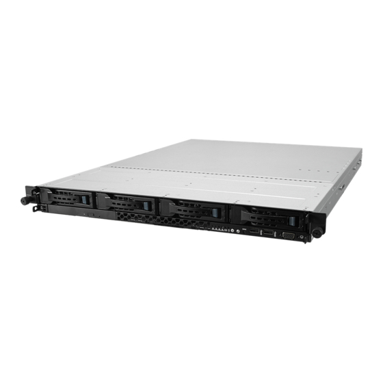
- Page 1 RS500-E9 Series RS500-E9-PS4 RS500-E9-RS4 RS500-E9-RS4-U 1U Rackmount Server User Guide...
- Page 2 ASUSTeK COMPUTER INC. (“ASUS”). ASUS provides this manual “as is” without warranty of any kind, either express or implied, including but not limited to the implied warranties or conditions of merchantability or fitness for a particular purpose. In no...
-
Page 3: Table Of Contents
Hard disk drives ..................2-9 Expansion slot ..................2-13 2.5.1 Installing an expansion card to the riser card bracket ....2-13 2.5.2 Installing an ASUS PIKE II card ..........2-14 2.5.3 Installing M.2 (NGFF) cards ............2-18 2.5.4 Installing Mezzanine cards ............2-20 2.5.5... - Page 4 Onboard LEDs ..................4-10 Internal connectors .................. 4-13 Chapter 5: BIOS Setup Managing and updating your BIOS ............5-2 5.1.1 ASUS CrashFree BIOS 3 utility........... 5-2 5.1.2 ASUS EZ Flash Utility ..............5-3 5.1.3 BUPDATER utility ............... 5-4 BIOS setup program .................. 5-6 5.2.1...
- Page 5 Contents 5.4.7 APM ..................5-16 5.4.8 PCI Subsystem Settings ............5-17 5.4.9 Network Stack Configuration............. 5-21 5.4.10 CSM Configuration ..............5-22 5.4.11 NVMe Configuration ..............5-23 5.4.12 USB Configuration ..............5-23 5.4.13 iSCSI Configuration ..............5-24 Platform Configuration menu ..............5-24 5.5.1 PCH Configuration ..............
- Page 6 Management applications and utilities installation ........ 7-5 Running the Support DVD ................. 7-5 Installing the system drivers ..............7-6 Appendix Z11PR-D16-DC block diagram ................A-2 Q-Code table ......................A-3 Notices ........................A-6 REACH ....................A-7 Australia statement notice ................A-7 ASUS contact information ..................A-8...
-
Page 7: Safety Information
Safety information Electrical Safety • Before installing or removing signal cables, ensure that the power cables for the system unit and all attached devices are unplugged. • To prevent electrical shock hazard, disconnect the power cable from the electrical outlet before relocating the system. -
Page 8: About This Guide
About this guide Audience This user guide is intended for system integrators, and experienced users with at least basic knowledge of configuring a server. Contents This guide contains the following parts: Chapter 1: Product Introduction This chapter describes the general features of the server, including sections on front panel and rear panel specifications. - Page 9 Refer to the following sources for additional information, and for product and software updates. ASUS Control Center (ACC) user guide This manual tells how to set up and use the proprietary ASUS server management utility. ASUS websites The ASUS websites worldwide provide updated information for all ASUS hardware and...
-
Page 11: Chapter 1: Product Introduction
Chapter 1: Product Introduction Product Introduction This chapter describes the general features of the chassis kit. It includes sections on front panel and rear panel specifications. -
Page 12: System Package Contents
System package contents Check your system package for the following items. Model Name RS500-E9-PS4, RS500-E9-RS4, RS500-E9-RS4-U Chassis ASUS R10E 1U Rackmount Chassis Motherboard ASUS Z11PR-D16-DC Server Board 1 x 650W Single Power Supply (RS500-E9-PS4) 1 x 770W Redundant Power Supply (RS500-E9-RS4, RS500-E9-RS4-U) 4 x Hot-swap 3.5-inch HDD Trays... -
Page 13: Serial Number Label
Serial number label Before requesting support from the ASUS Technical Support team, you must take note of the product’s serial number containing 12 characters such as xxS0xxxxxxxx shown as the figure below. With the correct serial number of the product, ASUS Technical Support team members can then offer a quicker and satisfying solution to your problems. -
Page 14: System Specifications
System specifications The ASUS RS500-E9 Series is a 1U barebone server system featuring the ASUS ® ® ® Z11PR-D16-DC Server Board. The server supports Intel LGA2011-3 Intel Xeon E5-2600 Processor v3 plus other latest technologies through the chipsets onboard. RS500-E9-PS4... - Page 15 Enterprise Linux ® SuSE Linux Enterprise Server CentOS OS Support Ubuntu VMware Citrix XenServer * Please find the latest OS support from http://www.asus.com/ ASUS Control Center Software Management Out of Band Solution Remote On-Board ASMB9-iKVM for KVM-over-IP Management Regulatory Compliance...
- Page 16 RS500-E9-PS4 RS500-E9-RS4 RS500-E9-RS4-U Model Name 1 + 1 R e d u n d a n t 7 7 0 W 8 0 P L U S Platinum Power Supply Rating: 100-240 Vac, 10A/5A, 50-60Hz, Single 650W 80 PLUS Class I Power Supply Platinum Power Supply (following different...
-
Page 17: Front Panel Features
OCP 2.0 Mezzanine slot RS500-E9-PS4 Power cord connector Locate LED PCI-E slot and power supply Q-Code LED LAN port for iKVM* Message LED OCP 2.0 Mezzanine slot Power button *This port is for ASUS ASMB9-iKVM controller card only. ASUS RS500-E9 Series... -
Page 18: Internal Features
Internal features The barebone server includes the basic components as shown. Power supply and power fan PCI Express slot Riser Card ASUS Z11PR-D16-DC Server Board System fans SAS / SATA backplane (hidden) Z11PR-D16-DC HDD tray 1 - Connects to SATA1 port... -
Page 19: Led Information
A hardware monitor event is indicated Normal status Location LED Location switch is pressed (Press the location switch again to turn off) No LAN connection Blinking LAN LEDs LAN is transmitting or receiving data LAN connection is present ASUS RS500-E9 Series... -
Page 20: Lan (Rj-45) Leds
1.7.2 LAN (RJ-45) LEDs LAN port LED indications ACT/LINK SPEED Activity/Link LED Speed LED Status Description Status Description No link GREEN Linked GREEN 1 Gbps connection BLINKING Data activity LAN port Dedicated Management LAN port (DM_LAN1) LED indications ACT/LINK SPEED Activity/Link LED Speed LED Status... -
Page 21: Chapter 2: Hardware Information
Chapter 2: Hardware Information Hardware Information This chapter lists the hardware setup procedures that you have to perform when installing or removing system components. -
Page 22: Chassis Cover
Chassis cover Removing the rear cover Locate and remove the front side screws. Front side screw Loosen the two thumbscrews on the rear panel to release the rear cover from the chassis. Thumbscrews Firmly hold the cover and slide it toward the rear panel for about half an inch until it is disengaged from the chassis. -
Page 23: Central Processing Unit (Cpu)
Contact your retailer immediately if the PnP cap is missing, or if you see any damage to the PnP cap/socket contacts/motherboard components. ASUS will shoulder the cost of repair only if the damage is shipment/ transit-related. - Page 24 Align the triangle mark on the CPU with the triangle mark on the CPU Carrier (A), then install the CPU into the CPU Carrier until it clicks firmly into place (B), and then install the CPU Carrier into the CPU Carrier heatsink until it clicks firmly in place (C).
- Page 25 Reinstall the air ducts. CPU2 (CPU socket 2) CPU1 (CPU socket 1) ASUS RS500-E9 Series...
-
Page 26: System Memory
System memory 2.3.1 Overview The motherboard comes with sixteen (16) Double Data Rate 4 (DDR4) Dual Inline Memory Modules (DIMM) sockets. The figure illustrates the location of the DDR4 DIMM sockets: 2.3.2 Memory Configurations You may install 32GB, 16GB, 8GB, 4GB RDIMM, 64GB, 32GB LRDIMM, or 128GB, 64GB LRDIMM 3DS into the DIMM sockets using the memory configurations in this section. - Page 27 6 DIMMs 8 DIMMs Dual CPU configuration You can refer to the following recommended memory population for a dual CPU configuration. Dual CPU configuration DIMM (CPU1) DIMM (CPU2) 2 DIMMs 4 DIMMs 8 DIMMs 12 DIMMs 16 DIMMs ASUS RS500-E9 Series...
-
Page 28: Installing A Dimm On A Single Clip Dimm Socket
2.3.3 Installing a DIMM on a single clip DIMM socket Ensure to unplug the power supply before adding or removing DIMMs or other system components. Failure to do so may cause severe damage to both the motherboard and the components. Unlock a DIMM socket by pressing the DIMM notch retaining clip outward. -
Page 29: Hard Disk Drives
Firmly hold the tray lever and pull the drive tray out of the bay. Place the drive tray on a flat and stable surface. Prepare the SATA/SAS HDD and the bundled set of screws. ASUS RS500-E9 Series... - Page 30 Place the 3.5” SATA/SAS HDD into the tray then secure it with four screws. Insert the drive tray and HDD assembly all the way into the depth of the bay until just a small fraction of the tray edge protrudes. When installed, the SATA/SAS connector on the drive connects to the SATA/SAS interface on the backplane.
- Page 31 Firmly hold the tray lever and pull the tray out of the bay. Place the tray on a flat and stable surface. Prepare the 2.5” storage device and the bundled set of screws. ASUS RS500-E9 Series 2-11...
- Page 32 Place the 2.5” storage device into the tray then secure it with four screws. Insert the tray and storage device assembly all the way into the depth of the bay until just a small fraction of the tray edge protrudes. When installed, the SATA/NVMe connector on the storage device connects to the SATA/ NVMe interface on the backplane.
-
Page 33: Expansion Slot
Place the riser card bracket on a flat and stable surface, then remove the screw from the slot bay. Install a PCI Express x8 or x16 card to the bracket as shown. Secure the card with a screw. ASUS RS500-E9 Series 2-13... -
Page 34: Installing An Asus Pike Ii Card
2.5.2 Installing an ASUS PIKE II card You can install an ASUS PIKE II card on the provided PCI-E slot onboard. To install an ASUS PIKE II card: Firmly hold the riser card bracket, then pull it up to detach it from the PCI Express x24 slot on the motherboard. - Page 35 Prepare your ASUS PIKE II card. Insert the expansion card into the PCI-E slot. Ensure that the golden fingers are totally inserted into the slot, then secure the ASUS PIKE II card with the screw removed before. ASUS RS500-E9 Series...
- Page 36 Remove the default mini-SAS HD cable from the motherboard. Z11PR-D16-DC Connect the mini-SAS HD cable to connector 1 of the ASUS PIKE II card. Connect to PIKE II connector 1 2-16 Chapter 2: Hardware Information...
- Page 37 Reinstall the riser card bracket into the PCI Express x24 slot on the motherboard. Ensure that the golden connectors of the riser card bracket is firmly seated in place. ASUS RS500-E9 Series 2-17...
-
Page 38: Installing M.2 (Ngff) Cards
2.5.3 Installing M.2 (NGFF) cards To install an M.2 (NGFF) card: Locate the M.2 (NGFF) connectors on your motherboard. Top screw Stand screw Remove the top screw and the stand from the motherboard. Select an appropriate screw hole on the motherboard for your M.2 card, then secure the stand to the motherboard. - Page 39 M.2 card matches the stand screw on the motherboard. Secure the M.2 card with the top screw. Ensure that the M.2 card is positioned between the top screw and the stand screw before securing it. ASUS RS500-E9 Series 2-19...
-
Page 40: Installing Mezzanine Cards
2.5.4 Installing Mezzanine cards To install a Mezzanine card: Locate the Mezzanine card connector on your motherboard. Firmly hold the riser card bracket, then pull it up to detach it from the PCI Express x24 slot on the motherboard. 2-20 Chapter 2: Hardware Information... - Page 41 Mezzanine card into the MEZZPCIE1 (OCP) connector on the motherboard. Ensure that the stand screws on the motherboard is aligned and matched to the screw holes of the Mezzanine card. LAN ports Screw holes LAN port slots Stand screws ASUS RS500-E9 Series 2-21...
- Page 42 Secure the Mezzanine card with the four (4) bundled screws. Connect the signal end (black) to the OCP_LED1 header on the motherboard. The two ends of the signal cable are different in size and color for easy recognition. Please refer to your exact cable. Reinstall the riser card bracket into the PCI Express x24 slot on the motherboard.
-
Page 43: Configuring An Expansion Card
ACPI Mode when used IRQ Holder for PCI Steering IRQ Holder for PCI Steering PS/2 Compatible Mouse Port Numeric Data Processor Primary IDE Channel Secondary IDE Channel * These IRQs are usually available for ISA or PCI devices. ASUS RS500-E9 Series 2-23... -
Page 44: Cable Connections
Cable connections • The bundled system cables are pre-connected before shipment. You do not need to disconnect these cables unless you will remove pre-installed components to install additional devices. • Refer to Chapter 4 for detailed information on the connectors. Standard cables connected to the motherboard 24-pin ATX power connector (from power supply to motherboard) 8-pin 12V power connector (from power supply to motherboard) -
Page 45: Sata/Sas Backplane Cabling
Connect the SATA/SAS storage device RS500-E9-RS4-U Connects the data cables connected to the motherboard BP4LE12G-35-RIDE Connects an 8-pin plug Connects the data cables connected to the motherboard from power supply Connects to the SATA/SAS/NMVE storage device ASUS RS500-E9 Series 2-25... -
Page 46: Removable/Optional Components
Removable/optional components You may need to remove previously installed system components when installing or removing system devices. Or you may need to install the optional components into the system. This section tells how to remove/install the system fans: Ensure that the system is turned off before removing any components from your system. 2.8.1 System fans To uninstall the system fans:... -
Page 47: Chapter 3: Installation Options
Chapter 3: Installation Options Installation Options This chapter describes how to install the optional components and devices into the barebone server. -
Page 48: Rail Kit Installation
Rail kit installation 3.1.1 Tool-less Friction Rail Kit The tool less design of the rail kit allows you to easily install the rack rails into the server rack without the need for additional tools. The kit also comes with a metal stopping bracket that can be installed to provide additional support and stability to the server. - Page 49 Select a desired space and place the appropriate rack rail (left and right) on opposite positions on the rack. A 1U space consists of three square mounting holes with two thin lips on the top and the bottom. ASUS RS500-E9 Series...
- Page 50 Secure the rail components to the rail using the bundled screws. Press the spring lock ( ) then insert the studs into the selected square mounting holes on the rack post. Press the spring lock on the other end of rail then insert the stud into the mounting hole on the rack post.
-
Page 51: Rail Kit Dimensions
Rail kit dimensions 43.6mm 900mm 43.6mm 589mm ASUS RS500-E9 Series... - Page 52 Chapter 3: Installation Options...
-
Page 53: Chapter 4: Motherboard Information
Chapter 4: Motherboard Information Motherboard Information This chapter includes the motherboard layout and brief descriptions of the jumpers and internal connectors. -
Page 54: Motherboard Layout
Motherboard layout Chapter 4: Motherboard Information... - Page 55 4-24 Serial ATA 6.0Gb/s connectors (7-pin SSATA1-4) 4-13 LAN controller setting (3-pin LAN_SW1) Mezzanine PCIE card connectors (MEZZPCIE1-2) 4-22 OCP LAN Activity LED connector (4-1 pin OCP_LED1) 4-23 M.2 (NGFF) connectors (NGFF1-2) 4-22 OCUPCIE connectors (OCUPCIE1-4) 4-21 ASUS RS500-E9 Series...
-
Page 56: Jumpers
Jumpers Clear RTC RAM (3-pin CLRTC1) This jumper allows you to clear the Real Time Clock (RTC) RAM in CMOS. You can clear the CMOS memory of date, time, and system setup parameters by erasing the CMOS RTC RAM data. The onboard button cell battery powers the RAM data in CMOS which include system setup information such as system passwords. - Page 57 This jumper allows you to enable or disable the onboard VGA controller. Set to pins 1–2 to activate the VGA feature. LAN controller setting (3-pin LAN_SW1) This jumper allows you to enable or disable the onboard LAN_SW1. Set to pins 1-2 to activate the Gigabit LAN feature. ASUS RS500-E9 Series...
- Page 58 ME firmware force recovery setting (3-pin ME_RCVR1) ® This jumper allows you to force Intel Management Engine (ME) boot from recovery mode when ME becomes corrupted. DDR4 thermal event setting (3-pin DIMMTRIP1-2) These jumpers allow you to enable or disable DDR4 DIMM thermal sensing event pin. Chapter 4: Motherboard Information...
- Page 59 This jumper allows you to enable or disable the Baseboard Management Controller (ASMB9). DMLAN setting (3-pin DM_IP_SEL1) This jumper allows you to select the DMLAN setting. Set to pins 2-3 to force the DMLAN IP to static mode (IP=10.10.10.10, submask=255.255.255.0). ASUS RS500-E9 Series...
- Page 60 PCH_MFG1 setting (3-pin PCH_MFG1) This jumper allows you to update the BIOS ME block. LANNCSI setting (3-pin LANNCSI_SEL1) This jumper allows you to select which LAN NCSI to function. Chapter 4: Motherboard Information...
- Page 61 This jumper allows you to enable or disable the Smart Ride Through (SmaRT) function. This feature is enabled by default. Set to pins 2-3 to disable it. When enabled, SmaRT allows uninterrupted operation of the system during an AC loss event. ASUS RS500-E9 Series...
-
Page 62: Onboard Leds
The illustration below shows the location of the onboard LED. BMC LED (BMCLED1) The BMC LED lights up to indicate that the on-board BMC is functional. This LED functions only when you enable ASUS ASMB9. Chapter 4: Motherboard Information 4-10... - Page 63 The Location LED helps visually locate and quickly identify the server in error on a server rack. CATT LED (CATTERR_LED1) The CATT LED indicates that the system has experienced a fatal or catastrophic error and cannot continue to operate. ASUS RS500-E9 Series 4-11...
- Page 64 Message LED (MESLED1) This onboard LED lights up to red when there is a BMC event log is generated. Hard disk activity LED (HDDLED1) This LED is for the storage devices connected to the onboard SATA, or SATA/SAS add-on card. The read or write activities of any device connected to the onboard SATA, or SATA/SAS add-on card causes the rear panel LED to light up.
-
Page 65: Internal Connectors
This connector allows you to connect SMBus (System Management Bus) to the PSU (power supply unit) to read PSU information. Devices communicate with an SMBus host and/or other SMBus devices using the SMBus interface. This connector functions only when you enable ASUS ASMB9. ASUS RS500-E9 Series 4-13... - Page 66 USB 2.0 connector (10-1 pin USB9_10; USB78) The 10-1 pin connector allows you to connect a USB 2.0 module for additional USB 2.0 front or rear panel ports. The 4-pin USB (Universal Serial Bus) Type-A port is available for connecting USB 2.0 devices. These USB connectors comply with USB 2.0 specification that supports up to 480 Mbps connection speed.
- Page 67 These are not jumpers! DO NOT place jumper caps on the fan connectors! • All fans feature the ASUS Smart Fan technology. LAN Activity LED connector (5-1 pin LAN34_LED1) These leads are for 10G LAN activity LEDs on the front panel. Connect the LAN LED cable to the backplane for LAN activity indication.
- Page 68 Serial port connector (10-1 pin COM1) This connector is for the serial COM port. Connect the serial port module cable to one of these connectors, then install the module to a slot opening at the back of the system chassis. Trusted Platform Module connector (20-1 pin TPM1) This connector supports a Trusted Platform Module (TPM) system, which can securely store keys, digital certificates, passwords, and data.
- Page 69 • This motherboard supports ATX2.0 PSU or later version. • Ensure that your PSU can provide at least the minimum power required by your system. ASUS RS500-E9 Series 4-17...
- Page 70 System panel connector (20-1 pin PANEL1) This connector supports several chassis-mounted functions. System power LED (3-pin PLED) This 3-pin connector is for the system power LED. Connect the chassis power LED cable to this connector. The system power LED lights up when you turn on the system power, and blinks when the system is in sleep mode.
- Page 71 These leads are for the locator button on the front panel. This button queries the state of the system locator. LAN activity LED and USB port (2-pin LAN3_LED, LAN4_LED, USB ports) These leads are for the Gigabit LAN activity LEDs and USB ports on the front panel. ASUS RS500-E9 Series 4-19...
- Page 72 VGA connector (10-1 pin VGA_HDR1) This connector supports the VGA High Dynamic-Range interface. Hard disk activity LED connector (4-pin HDLED1) This LED connector is for the storage add-on card cable connected to the SATA or SAS add-on card. The read or write activities of any device connected to the SATA or SAS add-on card causes the front panel LED to light up.
- Page 73 The default setting is short CASEOPEN and GND pin by jumper cap to disable the function. OCUPCIE connectors (OCUPCIE1-4) Connects the PCIE signal to the NVME port on the backplane. ASUS RS500-E9 Series 4-21...
- Page 74 M.2 (NGFF) connectors (NGFF1-2) These connectors allow you to install M.2 devices. This connector supports type 2242/2260/2280/22110 devices on both PCI-E and SATA interface. The M.2 (NGFF) device is purchased separately. Mezzanine PCIE card connectors (MEZZPCIE1-2) The MEZZPCIE1-2 connector supports Open Compute Project (OCP) cards. Chapter 4: Motherboard Information 4-22...
- Page 75 Memory Card, then reboot the system to access the Memory Card. • This Micro SD card slot functions only when you enable ASUS ASMB9. • Some memory cards may not be compatible with your motherboard. Ensure that you use only compatible memory cards to prevent loss of data, damage to your device, or memory card, or both.
- Page 76 Thermal sensor cable connector (3-pin TR1) This connector allows you to connect a thermal sensor cable that is used for monitoring temperature. Connect the thermal sensor cable to the connector and place its probe to the device that you want to monitor. Mini-SAS HD connectors (ISATA1-2) This motherboard comes with mini Serial Attached SCSI (SAS) HD connectors, the storage technology that supports Serial ATA.
- Page 77 VPP_I2C1 connector (10-1 pin VPP_I2C1) This connector is used for the Intel VMD function and sensor readings. VROC_KEY connector (4-pin VROC_KEY1) This connector allows you to connect a KEY module to support Intel VMD RAID function. ASUS RS500-E9 Series 4-25...
- Page 78 System Management Bus (SMBUS) connector (5-1 pin SMBUS1) This connectors controls the system and power management-related tasks. This connector processes the messages to and from devices rather than tripping the individual control lines. Chapter 4: Motherboard Information 4-26...
-
Page 79: Chapter 5: Bios Setup
Chapter 5: BIOS Setup BIOS Setup This chapter tells how to change the system settings through the BIOS Setup menus. Detailed descriptions of the BIOS parameters are also provided. -
Page 80: Managing And Updating Your Bios
BIOS in the future. Copy the original motherboard BIOS using the BUPDATER utility. 5.1.1 ASUS CrashFree BIOS 3 utility The ASUS CrashFree BIOS 3 is an auto recovery tool that allows you to restore the BIOS file when it fails or gets corrupted during the updating process. You can update a corrupted BIOS file using a USB flash drive that contains the updated BIOS file. -
Page 81: Asus Ez Flash Utility
5.1.2 ASUS EZ Flash Utility The ASUS EZ Flash Utility feature allows you to update the BIOS without having to use a DOS-based utility. Before you start using this utility, download the latest BIOS from the ASUS website at www.asus.com. To update the BIOS using EZ Flash Utility: Insert the USB flash disk that contains the latest BIOS file into the USB port. Enter the BIOS setup program. Go to the Tool menu then select ASUS EZ Flash Utility. -
Page 82: Bupdater Utility
The BUPDATER utility allows you to update the BIOS file in the DOS environment using a bootable USB flash disk drive with the updated BIOS file. Updating the BIOS file To update the BIOS file using the BUPDATER utility: Visit the ASUS website at www.asus.com and download the latest BIOS file for the motherboard. Save the BIOS file to a bootable USB flash disk drive. Copy the BUPDATER utility (BUPDATER.exe) from the ASUS support website at https://www.asus.com/support to the bootable USB flash disk drive you created earlier. Boot the system in DOS mode, then at the prompt, type: BUPDATER /i[filename].CAP where [filename] is the latest or the original BIOS file on the bootable USB flash disk drive, then press <Enter>. A:\>BUPDATER /i[file name].CAP... - Page 83 The utility verifies the file, then starts updating the BIOS file. ASUS Tek. EzFlash Utility Current Platform New Platform Platform : Z11PR-D16-DC Platform : Z11PR-D16-DC Version : 0201 Version : 0207 Build date: 12/04/2018 Build date: 01/05/2018 Start Programming Flash. DO NOT SHUTDOWN THE SYSTEM!!! Write DO NOT shut down or reset the system while updating the BIOS to prevent system boot failure! The utility returns to the DOS prompt after the BIOS update process is completed.
-
Page 84: Bios Setup Program
If the system becomes unstable after changing any BIOS settings, load the default settings to ensure system compatibility and stability. Press <F5> and select Yes to load the BIOS default settings. • The BIOS setup screens shown in this section are for reference purposes only, and may not exactly match what you see on your screen. • Visit the ASUS website (www.asus.com) to download the latest BIOS file for this motherboard. Chapter 5: BIOS Setup... -
Page 85: Bios Menu Screen
For changing the event log settings Server Mgmt For changing the server mgmt settings For changing the security settings Security Boot For changing the system boot configuration Tool For configuring options for special functions For selecting the save & exit options Save & Exit To select an item on the menu bar, press the right or left arrow key on the keyboard until the desired item is highlighted. ASUS RS500-E9 Series... -
Page 86: Menu Items
5.2.3 Menu items The highlighted item on the menu bar displays the specific items for that menu. For example, selecting Main shows the Main menu items. The other items (Advanced, Platform Configuration, Socket Configuration, Event Logs, Server Mgmt, Security, Boot, Tool, and Save & Exit) on the menu bar have their respective menu items. 5.2.4 Submenu items A solid triangle before each item on any menu screen means that the item has a submenu. To display the submenu, select the item then press <Enter>. 5.2.5 Navigation keys At the bottom right corner of a menu screen are the navigation keys for the BIOS setup program. Use the navigation keys to select items in the menu and change the settings. 5.2.6 General help At the top right corner of the menu screen is a brief description of the selected item. -
Page 87: Main Menu
Main menu When you enter the BIOS Setup program, the Main menu screen appears. The Main menu provides you an overview of the basic system information, and allows you to set the system date, time, language, and security settings. 5.3.1 System Date [Day xx/xx/xxxx] Allows you to set the system date. 5.3.2 System Time [xx:xx:xx] Allows you to set the system time. ASUS RS500-E9 Series... -
Page 88: Advanced Menu
The Advanced menu items allow you to change the settings for the CPU and other system devices. Take caution when changing the settings of the Advanced menu items. Incorrect field values can cause the system to malfunction. Optimized Performance Settings [Default] This option allows you to select a recommended BIOS setting to optimize performance. Asus Turbo Ratio Lock (ATRL) [Disabled] Allows you to keep the processor operating at the turbo highest frequency for maximum performance. Configuration options: [Disabled] [Enabled] 5.4.1 Trusted Computing... -
Page 89: Acpi Settings
Allows you to enable or disable the ability of the system to hibernate (OS/S4 Sleep State). Configuration options: [Disabled] [Enabled] This option may be not be effective with some OS. 5.4.3 Smart Settings SMART Self Test [Enabled] Allows you to run SMART Self Test on all HDDs during POST. Configuration options: [Disabled] [Enabled] ASUS RS500-E9 Series 5-11... -
Page 90: Super Io Configuration
5.4.4 Super IO Configuration Serial Port 1 Configuration Allows you to set the parameters of Serial Port 1. Serial Port [Enabled] Allows you to enable or disable Serial Port. Configuration options: [Disabled] [Enabled] The following item appears only when you set Serial Port to [Enabled]. Change Settings [Auto] Allows you to choose the setting for Super IO device. - Page 91 Parity [None] A parity bit can be sent with the data bits to detect some transmission errors. [Mark] and [Space] parity do not allow for error detection. [None] None. [Even] parity bit is 0 if the num of 1’s in the data bits is even. [Odd] parity bit is 0 if num of 1’s in the data bits is odd. [Mark] parity bit is always 1. [Space] parity bit is always 0. Stop Bits [1] Stop bits indicate the end of a serial data packet. (A start bit indicates the beginning.) The standard setting is 1 stop bit. Communication with slow devices may require more than 1 stop bit. Configuration options: [1] [2] ASUS RS500-E9 Series 5-13...
- Page 92 Flow Control [Hardware RTS/CTS] Flow control can prevent data loss from buffer overflow. When sending data, if the receiving buffers are full, a “stop” signal can be sent to stop the data flow. Once the buffers are empty, a “start” signal can be sent to re-start the flow. Hardware flow control uses two wires to send start/stop signals. Configuration options: [None] [Hardware RTS/CTS] VT-UTF8 Combo Key Support [Enabled] Allows you to enable the VT-UTF8 Combo Key Support for ANSI/VT100 terminals. Configuration options: [Disabled] [Enabled] Recorder Mode [Disabled] With this mode enabled only text will be sent. This is to capture Terminal data. Configuration options: [Disabled] [Enabled] Legacy OS Redirection Resolution [80x24] This allows you to set the number of rows and columns supported on the Legacy OS.
-
Page 93: Onboard Lan Configuration
Allows you to set the terminal type for out-of-band management. Configuration options: [VT100] [VT100+] [VT-UTF8] [ANSI] Bits per second [115200] Allows you to set the serial port transmission speed. Configuration options: [9600] [19200] [57600] [115200] Flow Control [None] Allows you to set the flow control to prevent data loss from buffer overflow. Configuration options: [None] [Hardware RTS/CTS] [Software Xon/Xoff] 5.4.6 Onboard LAN Configuration Onboard X722 LAN Configuration Intel X722 LAN Enable [Enabled] Allows you to enable or disable the Intel X722 LAN. Configuration options: [Disabled] [Enabled] ASUS RS500-E9 Series 5-15... -
Page 94: Apm
5.4.7 Allows you to configure the Advance Power Management (APM) settings. Restore AC Power Loss [Last State] When set to [Power Off], the system goes into off state after an AC power loss. When set to [Power On], the system will reboot after an AC power loss. When set to [Last State], the system goes into either off or on state, whatever the system state was before the AC power loss. Configuration options: [Power Off] [Power On] [Last State] Power On By PCIE [Disabled] [Disabled] Disables the PCIE devices to generate a wake event. [Enabled] Enables the PCIE devices to generate a wake event. Power On By RTC [Disabled] [Disabled] Disables RTC to generate a wake event. [Enabled] W hen set to [Enabled], the items RTC Alarm Date (Days) and Hour/Minute/Second will become user-configurable with set values. Chapter 5: BIOS Setup 5-16... -
Page 95: Pci Subsystem Settings
This option enables or disables SIngle Root IO Virtualization Support if the system has SRIOV capable PCIe devices. Configuration options: [Disabled] [Enabled] PCI Express Settings PCI Express Device Register Settings Relaxed Ordering [Enabled] This option allows you to enable or disable PCI Express Device Relaxed Ordering. Configuration options: [Disabled] [Enabled] Extended Tag [Disabled] This option allows Device to use an 8-bit Tag field as a requester when set to Enabled. Configuration options: [Disabled] [Enabled] ASUS RS500-E9 Series 5-17... - Page 96 No Snoop [Enabled] This option allows you to enable or disable PCI Express Device No Snoop option. Configuration options: [Disabled] [Enabled] Maximum Payload [Auto] This option allows you to set the Maximum Payload of PCI Express Device or allow System BIOS to select the value. Configuration options: [Auto] [128 Bytes] [256 Bytes] [512 Bytes] [1024 Bytes] [2048 Bytes] [4096 Bytes] Maximum Read Request [Auto]...
- Page 97 If supported by hardware and set to Enabled, this permits setting the number of ID- Based Ordering (IDO) bit (Attribute[2]) requests to be initiated. Configuration options: [Disabled] [Enabled] LTR Mechanism Enable [Disabled] If supported by hardware and set to Enabled, this enables the Latency Tolerance Reporting (LTR) Mechanism. Configuration options: [Disabled] [Enabled] End-End TLP Prefix Blocking [Disabled] If supported by hardware and set to Enabled, this function will block forwarding of TLPs containing End-End TLP Prefixes. Configuration options: [Disabled] [Enabled] ASUS RS500-E9 Series 5-19...
- Page 98 PCI Express GEN2 Device Register Settings Target Link Speed [Auto] If supported by hardware and set to Force to X.X GT/s, for Downstream Ports, this sets an upper limit on Link operational speed by restricting the values advertised by the Upstream component in its training sequences. When Auto is selected HW initialized data will be used. Configuration options: [Auto] [Force to 2.5 GT/s] [Force to 5.0 GT/s] [Force to 8.0 GT/s] Clock Power Management [Disabled] If supported by hardware and set to Enabled, the device is permitted to use CLKREQ# signal for power management of Link clock in accordance to protocol defined in appropriate form factor specification.
-
Page 99: Network Stack Configuration
Ipv6 PXE Support [Disabled] Enables or disables the Ipv6 PXE Boot Support. If disabled, Ipv6 PXE boot option will not be created. Configuration options: [Disable] [Enable] Ipv6 HTTP Support [Disabled] Enables or disables the Ipv6 HTTP Boot Support. If disabled, Ipv6 PXE boot option will not be created. Configuration options: [Disable] [Enable] PXE boot wait time [0] Set the wait time to press ESC key to abort the PXE boot. Use the <+> or <-> to adjust the value. The values range from 0 to 5. Media detect count [1] Set the number of times presence of media will be checked. Use the <+> or <-> to adjust the value. The values range from 1 to 50. ASUS RS500-E9 Series 5-21... -
Page 100: Csm Configuration
5.4.10 CSM Configuration CSM Support [Enabled] This option allows you to enable or disable CSM Support. Configuration options: [Disabled] [Enabled] The following items appear only when you set the CSM Support to [Enabled]. GateA20 Active [Upon Request] This allows you to set the GA20 option. [Upon Request] GA20 can be disabled using BIOS services. -
Page 101: Nvme Configuration
USB Mass Storage Driver Support [Enabled] Allows you to enable or disable the USB Mass Storage driver support. Configuration options: [Disabled] [Enabled] Mass Storage Devices Allows you to select the mass storage device emulation type for devices connected. Configuration options: [Auto] [Floppy] [Forced FDD] [Hard Disk] [CD-ROM] ASUS RS500-E9 Series 5-23... -
Page 102: Iscsi Configuration
5.4.13 iSCSI Configuration Allows you to configure the iSCSi parameters. Platform Configuration menu The IntelRCSetup menu items allow you to change the platform settings. Take caution when changing the settings of the Platform Configuration menu items. Incorrect field values can cause the system to malfunction. Chapter 5: BIOS Setup 5-24... -
Page 103: Pch Configuration
DeepSx Power Policies [Disabled] Allows you to configure the DeepSx Mode configuration. Configuration options: [Disabled] [Enabled in S5] [Enabled in S4 and S5] GP27 Wake From DeepSx [Disabled] Allows you to enable or disable GP27 Wake From DeepSx. Configuration options: [Disabled] [Enabled] PCI Express Configuration PCI-E ASPM Support (Global) [L1 Only] Allows you to select ASPM support for all downstream devices. Configuration options: [Per individual port] [L1 Only] PCH DMI ASPM [Platform-POR] Allows you to configure the PCH DMI ASPM. Configuration options: [Platform-POR] [ASPM L1] [Disabled] ASUS RS500-E9 Series 5-25... - Page 104 PCH SATA Configuration SATA Controller [Enabled] Allows you to enable or disable the SATA Controller. Configuration options: [Disabled] [Enabled] The following item appears only when you set SATA Controller to [Enabled]. Configure SATA as [AHCI] Allows you to identify the SATA port connected to Solid State Drive or Hard Disk Drive. Configuration options: [AHCI] [RAID] Support Aggressive Link Power Management [Enabled] Allows you to enable or disable the Support Aggressive Link Power (SALP) Management.
- Page 105 The following items appear only when the USB Per-Connector Disable is set to [Enabled]. USB_1-9 [Enabled] Configuration options: [Disabled] [Enabled] USB3_1-5 [Enabled] Configuration options: [Disabled] [Enabled] Security Configuration SMM BIOS Write Protect [Enabled] Allows you to enable or disable SMM BIOS Write Protect. Configuration options: [Disabled] [Enabled] DCI Auto Detect Enable [Disabled] When enabled, it detects DCI being connected during BIOS POST time and enables DCI. Configuration options: [Disabled] [Enabled] ASUS RS500-E9 Series 5-27...
-
Page 106: Miscellaneous Configuration
5.5.2 Miscellaneous Configuration Active Video [Offboard Device] Allows you to select the video type. Configuration options: [Onboard Device] [Offboard Device] PMTT ACPI Table [Disabled] Allows you to enable or disable PMTT ACPI Table for DDR4 only. Configuration options: [Disabled] [Enabled] 5.5.3 Server ME Configuration Displays the Server ME Technology parameters on your system. Navigate to the second page of the screen to see the rest of items in this menu by pressing the Up or Down arrow keys. -
Page 107: Runtime Error Logging
5.5.4 Runtime Error Logging Displays the Server ME Technology parameters on your system. System Errors [Enabled] This item allows you to enable or disable System Errors. Configuration options: [Disabled] [Enabled] Whea Settings Whea Support [Enabled] This item allows you to enable or disable the WHEA support. Configuration options: [Disabled] [Enabled] ASUS RS500-E9 Series 5-29... -
Page 108: Socket Configuration Menu
Socket Configuration menu The IntelRCSetup menu items allow you to change the socket settings. 5.6.1 Processor Configuration Navigate to the second page of the screen to see the rest of items in this menu by pressing the Up or Down arrow keys. To quickly go to the last item of the second page, press the Page Down button. Press the Page Up button to go back to the first item in the first page. Per-Socket Configuration CPU Socket 1/2 Configuration CPU Core Disable Bitmap(Hex) [0] This item allows you to enable or disable the cores on the CPU. - Page 109 DCU Mode [32KB 8Way Without ECC] Configuration options: [32KB 8Way Without ECC] [16KB 4Way With ECC] Extended APIC [Disabled] This Item allows you to enable or disable the extended APIC support. Configuration options: [Disabled] [Enabled] AES-NI [Enabled] This Item allows you to enable or disable the AES-NI support. Configuration options: [Disabled] [Enabled] ASUS RS500-E9 Series 5-31...
-
Page 110: Common Refcode Configuration
5.6.2 Common RefCode Configuration MMIO High Base [1T] This item allows you to select the MMIO High Base. Configuration options: [1T] [4T] [16T] [24T] [40T] [56T] MMIO High Granularity Size [256G] This item allows you to select the MMIO High Granularity Size. Configuration options: [1G] [4G] [16G] [64G] [256G] [1024G] Numa [Enabled] This item enables or disables the Non uniform Memory Access (NUMA). Configuration options: [Disabled] [Enabled] Chapter 5: BIOS Setup 5-32... -
Page 111: Upi Configuration
Link L0p Enable [Auto] Configuration options: [Disabled] [Enabled] [Auto] Link L1 Enable [Auto] Configuration options: [Disabled] [Enabled] [Auto] Directory Mode Enable [Enabled] Configuration options: [Disabled] [Enabled] SNC [Disabled] Configuration options: [Disabled] [Enabled] [Auto] KTI Prefetch [Enabled] Configuration options: [Disabled] [Enabled] Local/Remote Threshold [Auto] Configuration options: [Disabled] [Auto] [Low] [Medium] [High] Stale AtoS [Disabled] Configuration options: [Disabled] [Enabled] [Auto] LLC dead line alloc [Enabled] Configuration options: [Disabled] [Enabled] [Auto] ASUS RS500-E9 Series 5-33... -
Page 112: Memory Configuration
5.6.4 Memory Configuration Enforce POR [Auto] Allows you to enforce POR restrictions for DDR4 frequency and voltage programming. Configuration options: [Auto] [POR] [Disabled] Memory Frequency [Auto] Allows you to select the memory frequency setting. Configuration options: [Auto] [2133] [2400] [2666] Data Scrambling for DDR4 [Auto] Allows you to enable or disable data scrambling. Configuration options: [Auto] [Disabled] [Enabled] Memory Topology Displays memory topology with DIMM population information. -
Page 113: Iio Configuration
VT for Directed I/O (VT-d) [Enabled] ® Allows you to enable or disable the Intel Virtualization Technology for Directed I/O. Configuration options: [Disabled] [Enabled] IIO-PCIE Express Global Options PCIE relaxed Ordering [Enabled] Allows you to enable or disable PCIE relaxed Ordering. Configuration options: [Disabled] [Enabled] ASUS RS500-E9 Series 5-35... -
Page 114: Advanced Power Management Configuration
5.6.6 Advanced Power Management Configuration CPU P State Control Boot performance mode [Max Performance] Allows you to switch between Boot performance mode. Configuration options: [Max Performance] [Max Efficient] [Set by Intel Node Manager] Energy Efficient Turbo [Enabled] Allows you to enable or disable Energy Efficient Turbo. Configuration options: [Disabled] [Enabled] Turbo Mode [Enabled] Allows you to enable or disable Turbo Mode. Configuration options: [Disabled] [Enabled] Hardware PM State Control Hardware P-States [Native Mode]... - Page 115 ENERGY_PERF_BIAS_CFG Mode [Balanced Performance] Configuration options: [ Performance] [Balanced Performance] [Balanced Power] [Power] Dynamic Loadline Switch [Enabled] Configuration options: [Disabled] [Enabled] Workload Configuration [UMA] This option allows optimization for the workload characterization. Configuration options: [UMA] [NUMA] Averaging Time Window [17] This option is used to control the effective window of the average C0 an P0 time. Configuration options: [0] - [99] ASUS RS500-E9 Series 5-37...
-
Page 116: Event Logs Menu
P0 TotalTimeThreshold Low [23] The HW switching mechanism DISABLES the performance setting (0) when the total P0 time is less than the threshold set. Configuration options: [0] - [99] P0 TotalTimeThreshold High [3a] The HW switching mechanism Enables the performance setting (0) when the total P0 time is greater than the threshold set. Configuration options: [0] - [99] Event Logs menu 5.7.1 Change Smbios Event Log Settings Press <Enter> to change the Smbios Event Log configuration. All values changed here do not take effect until computer is restarted. Enabling/Disabling Options Smbios Event Log [Enabled] Change this to enable or disable all features of Smbios Event Logging during boot. -
Page 117: View Smbios Event Log
This item allows you to start a BIOS timer which can only be shut off by Intel Management Software after the OS loads. Configuration options: [Disabled] [Enabled] The following items are configurable only when the OS Watchdog Timer is set to [Enabled]. OS Wtd Timer Timeout [10 minutes] Allows you to configure the length for the OS Boot Watchdog Timer. Configuration options: [5 minutes] [10 minutes] [15 minutes] [20 minutes] OS Wtd Timer Policy [Reset] This item allows you to configure the how the system should respond if the OS Boot Watch Timer expires. Configuration options: [Do Nothing] [Reset] [Power Down] ASUS RS500-E9 Series 5-39... -
Page 118: System Event Log
5.8.1 System Event Log Allows you to change the SEL event log configuration. All values changed here do not take effect until computer is restarted. Erase SEL [No] Allows you to choose options for erasing SEL. Configuration options: [No] [Yes, On next reset] [Yes, On every reset] When SEL is Full [Do Nothing] Allows you to choose options for reactions to a full SEL. Configuration options: [Do Nothing] [Erase Immediately] 5.8.2 BMC network configuration The sub-items in this configuration allow you to configure the BMC network parameters. Navigate to the second page of the screen to see the rest of items in this menu by pressing the Up or Down arrow keys. -
Page 119: View System Event Log
Configuration options: [Previous State] [Static] [DynamicBmcDhcp] [DynamicBmcNonDhcp] IPV6 DM_LAN1/ Shared LAN IPV6 Support [Enabled] Allows you to enable or disable LAN1 IPV6 Support. Configuration options: [Disabled] [Enabled] Config Address source [Previous State] This item allows you to configure LAN channel parameters statistically or dynamically (by BIOS or BMC). Unspecified option will not modify any BMC network parameters during BIOS phase. Configuration options: [Previous State] [Static] [DynamicBmcDhcp] [DynamicBmcNonDhcp] 5.8.3 View System Event Log This item allows you to view the system event log records. ASUS RS500-E9 Series 5-41... -
Page 120: Security Menu
Security menu This menu allows a new password to be created or a current password to be changed. The menu also enables or disables the Secure Boot state and lets the user configure the System Mode state. Administrator Password To set an administrator password: 1. Select the Administrator Password item and press <Enter>. 2. From the Create New Password box, key in a password, then press <Enter>. 3. Confirm the password when prompted. To change an administrator password: 1. - Page 121 1. Select the User Password item and press <Enter>. 2. From the Create New Password box, key in a password, then press <Enter>. 3. Confirm the password when prompted. To change a user password: 1. Select the User Password item and press <Enter>. 2. From the Enter Current Password box, key in the current password, then press <Enter>. 3. From the Create New Password box, key in a new password, then press <Enter>. 4. Confirm the password when prompted. To clear a user password: 1. Select the Clear User Password item and press <Enter>. 2. Select Yes from the Warning message window then press <Enter>. ASUS RS500-E9 Series 5-43...
- Page 122 Secure Boot This item allows you to customize the Secure Boot settings. Secure Boot [Disabled] Secure Boot can be enabled if the system is running in User mode with platform Key (PK) enrolled and the CSM function is disabled. Configuration options: [Disabled] [Enabled] Secure Boot Customization [Custom] Allows you to set the Secure Boot selector.
- Page 123 Remove Microsoft UEFI CA from Secure Boot DB. Restore DB defaults Restore DB variable to factory defaults. Platform Key (PK) / Key Exchange Keys (KEK) / Authorized Signatures (DB) / Forbidden Signatures (DBX) / Authorized TimeStamps (DBT) / OsRecovery Signatures Configuration options: [Erase] [Set New] [Save to File] ASUS RS500-E9 Series 5-45...
-
Page 124: Boot Menu
These items specify the boot device priority sequence from the available devices. The number of device items that appears on the screen depends on the number of devices installed in the system. • To select the boot device during system startup, press <F8> when ASUS Logo appears. • To access Windows OS in Safe Mode, please press <F8> after POST. CD/DVD ROM Drive BBS Priorities / Network Device BBS Priorities These items allow you to set the booting order of the devices. -
Page 125: Tool Menu
IPMI Hardware Monitor Allows you to run the IPMI hardware monitor. Start EzFlash Allows you to run ASUS EzFlash BIOS ROM Utility when you press <Enter>. Refer to the ASUS EzFlash Utility section for details. 5.12 Save & Exit menu The Exit menu items allow you to save or discard your changes to the BIOS items. - Page 126 Boot Override These items displays the available devices. The device items that appears on the screen depends on the number of devices installed in the system. Click an item to start booting from the selected device. Launch EFI Shell from filesystem device This item allows you to attempt to launch the EFI Shell application (shellx64.efi) from one of the available filesystem devices. Chapter 5: BIOS Setup 5-48...
-
Page 127: Chapter 6: Raid Configuration
Chapter 6: RAID Configuration RAID Configuration This chapter provides instructions for setting up, creating, and configuring RAID sets using the available utilities. -
Page 128: Setting Up Raid
Setting up RAID ® The motherboard supports the Intel Rapid Storage Technology enterprise Option ROM Utility with RAID 0, RAID 1, RAID 10, and RAID 5 support. 6.1.1 RAID definitions RAID 0 (Data striping) optimizes two identical hard disk drives to read and write data in parallel, interleaved stacks. -
Page 129: Installing Hard Disk Drives
Go to the Platform Configuration Menu > PCH Configuration, then press <Enter>. Set Configure SATA as to [RAID Mode]. Press <F10> to save your changes and exit the BIOS Setup. Refer to Chapter 4 for details on entering and navigating through the BIOS Setup. ASUS RS500-E9 Series... -
Page 130: Intel ® Rapid Storage Technology Enterprise
® Intel Rapid Storage Technology enterprise SATA Option ROM Utility The Intel Rapid Storage Technology enterprise SATA Option ROM utility allows you to ® create RAID 0, RAID 1, RAID 10 (RAID 1+0), and RAID 5 set from Serial ATA hard disk drives that are connected to the Serial ATA connectors supported by the Southbridge. -
Page 131: Creating A Raid Set
]-Prev/Next [TAB]-(M)aster [SPACE]-(R)ecovery [ENTER]-Done Use the up/down arrow keys to move the selection bar then press <Space> to select a disk. A small triangle before the Port number marks the selected drive. Press <Enter> when you are done. ASUS RS500-E9 Series... - Page 132 Use the up/down arrow keys to select the stripe size for the RAID array (for RAID 0, 10 and 5 only) then press <Enter>. The available stripe size values range from 4 KB to 128 KB. The following are typical values: RAID 0: 128KB RAID 10:...
-
Page 133: Deleting A Raid Set
<N> to return to the DELETE VOLUME menu. DELETE VOLUME VERIFICATION ALL DATA IN THE VOLUME WILL BE LOST! (This does not apply to Recovery volumes) Are you sure you want to delete volume “Volume0”? (Y/N): ASUS RS500-E9 Series... -
Page 134: Resetting Disks To Non-Raid
6.2.3 Resetting disks to Non-RAID Take caution before you reset a RAID volume hard disk drive to non-RAID. Resetting a RAID volume hard disk drive deletes all internal RAID structure on the drive. To reset a RAID set: From the utility main menu, select 3. Reset Disks to Non-RAID and press <Enter>. Press the up/down arrow keys to select the drive(s) or disks of the RAID set you want to reset, then press <Space>. -
Page 135: Exiting The Intel Rapid Storage Technology Enterprise Sata Option Rom Utility
Rebuild completes in the operating system. Select the port of destination disk for rebuilding (ESC to exit): Port Drive Model Serial # Size XXXXXXXXXXX XXXXXXXX XXX.GB ]-Previous/Next [ENTER]-Select [ESC]-Exit Select a destination disk with the same size as the original hard disk. ASUS RS500-E9 Series... - Page 136 The utility immediately starts rebuilding after the disk is selected. When done, the status of the degraded RAID volume is changed to “Rebuild”. Intel(R) Rapid Storage Technology enterprise - SATA Option ROM - 3.6.0.1023 Copyright(C) 2003-12 Intel Corporation. All Rights Reserved. MAIN MENU 1.
-
Page 137: Setting The Boot Array In The Bios Setup Utility
Use up/down arrow keys to select the boot priority and press <Enter>. See the Boot menu section of Chapter 4 for more details. From the Exit menu, select Save Changes & Exit, then press <Enter>. When the confirmation window appears, select Yes, then press <Enter>. ASUS RS500-E9 Series 6-11... -
Page 138: Intel ® Rapid Storage Technology Enterprise (Windows)
® Intel Rapid Storage Technology enterprise (Windows) The Intel Rapid Storage Technology enterprise allows you to create RAID 0, RAID 1, RAID ® 10 (RAID 1+0), and RAID 5 set(s) from Serial ATA hard disk drives that are connected to the Serial ATA connectors supported by the Southbridge. -
Page 139: Creating A Raid Set
Click Next. • If you do not want to keep the data on one of the selected disks, select NO when prompted. • If you want to Enable volume write-back cache or Initialize volume, click Advanced. ASUS RS500-E9 Series 6-13... - Page 140 Confirm the volume creation, than click Create Volume to continue. This process could take a while depending on the number and size of the disks. You can continue using other applications during this time. Wait until the process is completed, then click OK when prompted. You still need to partition your new volume using Windows Disk Management before adding any data.
-
Page 141: Changing A Volume Type
RAID 0: 128KB RAID 10: 64KB RAID 5: 64KB We recommend a lower stripe size for server systems, and a higher stripe size for multimedia computer systems used mainly for audio and video editing. ASUS RS500-E9 Series 6-15... -
Page 142: Deleting A Volume
6.3.3 Deleting a volume Be cautious when deleting a volume. You will lose all data on the hard disk drives. Before you proceed, ensure that you back up all your important data from your hard drives. To delete a volume: From the utility main menu, select the volume (exp. -
Page 143: Preferences
Allow you to set to show the notification area icon and show system information, warning, or errors here. E-Mail Preferences Allow you to set to sent e-mail of the following events: • Storage system information • Storage system warnings • Storage system errors ASUS RS500-E9 Series 6-17... -
Page 144: Intel ® Virtual Raid On Cpu In Bios
Intel Virtual Raid on CPU in BIOS ® This feature requires a KEY module to enable CPU RAID functions with Intel CPU RSTe. ® • The KEY module is purchased separately. • Refer to section 4.4 Internal connectors for the location of the VROC_KEY1 connector. -
Page 145: Creating A Raid Set
RAID 0: 128 KB RAID 10: 64 KB RAID 5: 64 KB We recommend a lower strip size for server systems, and a higher strip size for multimedia computer systems used mainly for audio and video editing. ASUS RS500-E9 Series 6-19... - Page 146 When the Capacity (MB) item is selected, enter the RAID volume capacity that you want and press <Enter>. The default value indicates the maximum allowed capacity. When the Create Volume item is selected, press <Enter> to create the RAID volume and return to the Intel Rapid Storage Technology menu.
-
Page 147: Deleting A Raid Set
<Enter>. The following screen appears: When the Delete item is selected, press <Enter>, then select Yes to delete the RAID volume and return to the Intel Virtual Raid on CPU menu, or select No to cancel. ® ASUS RS500-E9 Series 6-21... - Page 148 Chapter 6: RAID Configuration 6-22...
-
Page 149: Chapter 7: Driver Installation
Chapter 7: Driver Installation Driver Installation This chapter provides the instructions for installing the necessary drivers for different system components in both ® ® Linux and Windows Operating Systems. -
Page 150: Raid Driver Installation
RAID driver installation After creating the RAID sets for your server system, you are now ready to install an operating system to the independent hard disk drive or bootable array. This part provides the instructions on how to install the RAID controller drivers during OS installation. 7.1.1 Creating a USB flash drive with RAID drive ®... - Page 151 Click Browse to continue. Locate the driver in the corresponding folder of the Support DVD or USB flash drive and then click OK to continue. Select the RAID controller driver you need from the list and click Next. ASUS RS500-E9 Series...
- Page 152 When the system finishes loading the RAID driver, Replace the motherboard Support DVD with the Windows Server installation disc. • Remove the USB flash drive. • Select the drive to install Windows and click Next. Setup then proceeds with the OS installation. Follow the onscreen instructions to continue.
-
Page 153: Management Applications And Utilities Installation
• The contents of the support DVD are subject to change at any time without notice. Visit the ASUS website (www.asus.com) for the latest updates on software and utilities. ®... -
Page 154: Installing The System Drivers
Installing the system drivers This section provides the instructions on how to install the system drivers. You will need to ® manually install the system drivers on a Windows operating system. To install the system drivers: Restart the computer, and then log on with Administrator privileges. Insert the support DVD into the optical drive. - Page 155 Follow the onscreen instructions to complete the installation. ASUS RS500-E9 Series...
- Page 156 Chapter 7: Driver Installation...
-
Page 157: Appendix
Appendix Appendix... -
Page 158: Z11Pr-D16-Dc Block Diagram
Z11PR-D16-DC block diagram... -
Page 159: Q-Code Table
Q-Code table Code Description Not used microcode CACHE_ENABLED PCH initialization CPU_EARLY_INIT PEI Core is started 11 – 14 Pre-memory CPU initialization is started Pre-memory System Agent initialization is started 15 – 18 19 – 1C Pre-memory PCH initialization is started 2B –... - Page 160 Code Description Invalid recovery capsule FB – FF Reserved for future AMI error codes DXE Core is started NVRAM initialization Installation of the PCH Runtime Services 63 – 67 CPU DXE initialization is started PCI host bridge initialization System Agent DXE initialization is started System Agent DXE SMM initialization is started 6B –...
- Page 161 Code Description Reserved for ASL (see ASL Status Codes section below) Ready To Boot event Legacy Boot event Exit Boot Services event Runtime Set Virtual Address MAP Begin Runtime Set Virtual Address MAP End Legacy Option ROM Initialization System Reset USB hot plug PCI bus hot plug Clean-up of NVRAM...
-
Page 162: Notices
Notices Federal Communications Commission Statement This device complies with Part 15 of the FCC Rules. Operation is subject to the following two conditions: • This device may not cause harmful interference, and • This device must accept any interference received including interference that may cause undesired operation. -
Page 163: Reach
If you require assistance please call ASUS Customer Service 1300 2787 88 or visit us at https://www.asus.com/support/. -
Page 164: Asus Contact Information
ASUS contact information ASUSTeK COMPUTER INC. Address 4F, No. 150, Li-Te Rd., Peitou, Taipei 112, Taiwan Telephone +886-2-2894-3447 +886-2-2890-7798 Web site https://www.asus.com Technical Support Telephone +86-21-38429911 +86-21-58668722 ext: 9101 Online Support https://www.asus.com/support/Product/ContactUs/Services/ questionform/?lang=en ASUSTeK COMPUTER INC. (Taiwan) Address 4F, No. 150, Li-Te Rd., Peitou, Taipei 112, Taiwan... - Page 165 +1-510-608-4555 Web site https://www.asus.com/us/ Technical Support Support fax +1-812-284-0883 General support +1-812-282-2787 Online support https://www.asus.com/support/Product/ContactUs/Services/ questionform/?lang=en-us ASUS COMPUTER GmbH (Germany and Austria) Address Harkort Str. 21-23, 40880 Ratingen, Germany +49-2102-959911 Web site https://www.asus.com/de/ Technical Support Telephone +49-1805-010923 Support Fax +49-2102-959911 Online support https://www.asus.com/support/Product/ContactUs/Services/...
- Page 166 Web site https://www.asus.com/nl/ Technical Support Telephone +31-(0)591-5-70292 +31-(0)591-666853 E-mail advance.rma.eu@asus.com Online Support https://www.asus.com/support/Product/ContactUs/Services/ questionform/?lang=nl-nl ASUS Polska Sp. z o.o. (Poland) Address Ul. Postępu 6, 02-676 Warszawa, Poland Web site https://www.asus.com/pl/ Technical Support Telephone +48-225718033 Online Support https://www.asus.com/support/Product/ContactUs/Services/ questionform/?lang=pl-pl ASK-Service (Russia and CIS) Address г.Москва, ул.