Sony WRR-800A Operating Instructions Manual
Uhf synthesized diversity tuner
Hide thumbs
Also See for WRR-800A:
- Operating instructions manual (52 pages) ,
- Service manual (46 pages)

Related Manuals for Sony WRR-800A


Summary of Contents for Sony WRR-800A
- Page 1 3-860-929-31 (1) UHF Synthesized Diversity Tuner Operating Instructions WRR-800A [AU] © 1997 by Sony Corporation...
-
Page 2: Precautions
Precautions • Switching lights on or off may produce electrical WARNING interference over the entire frequency range. Position the unit and the wireless microphones so that interference is To prevent fire or shock hazard, do not expose the unit minimized. to rain or moisture. -
Page 3: Table Of Contents
Rear Panel ............11 Phase Locked Loop (PLL) synthesized system Operation ..............12 The WRR-800A has a refined phase locked loop (PLL) Muting Functions ..........13 synthesizer circuit and covers two UHF TV channels. It operates on 102 channels over a 14-MHz frequency. -
Page 4: System Configuration
System Configuration A liquid-crystal display provides a variety of information, including the levels of the reception channels, RF The unit can be used with a Sony UHF synthesized wireless microphone or UHF synthesized transmitter among the information and transmitter battery condition. -
Page 5: Wirelss Channels Selectable
Wirelss Channels Selectable The unit stores 13 groups of selectable channels: • The number of wireless microphone channels actually groups 00 (102 channels), 11 (12 channels), 12 (9 channels), usable in a multi-channel system may be smaller than the 13 (9 channels), A1 (8 channels), A2 (6 channels), normal capacity of that system if there is interference from A3 (6 channels), L1 (6 channels), L2 (6 channels), TV broadcasting or other RF signals. -
Page 6: Wireless Channel Lists
Wirelss Channels Selectable Wireless Channel Lists Group 00: All channel access Use only for a one-channel system or to scan for open channels. WL Channel Frequency (MHz) WL Channel Frequency (MHz) Channel Frequency (MHz) Channel Frequency (MHz) 66-27 795.500 66-01 792.250 67-01 799.250... - Page 7 Group 11: 12-channel group Group 12: 9-channel group Group 13: 9-channel group Use when TV channels both 66 and Use when TV channel 66 is on the air. Use when TV channel 67 is on the air. 67 are available. WL Channel Frequency (MHz) WL Channel Frequency (MHz) WL Channel Frequency (MHz)
- Page 8 Wirelss Channels Selectable Group L1: 6-channel group Group M1: 6-channel group Group H1: 8-channel group Use when TV channel 67 is on the air. Use when TV channel 67 is on the air. Use when TV channel 66 is on the air. WL Channel Frequency (MHz) WL Channel Frequency (MHz) WL Channel Frequency (MHz)
-
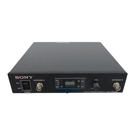
Page 9: Location Of Parts And Controls
Location of Parts and Controls Front Panel 1 POWER switch 2 ANTENNA A, B connectors 3 Display ANTENNA A VOL. ANTENNA B BATT BATT POWER 4 SET button 7 VOL. Control 5 GP button 6 CH button 1 POWER switch 3 Display Turns the power on and off. -
Page 10: Display
Location of Parts and Controls 5 GP (group) button 1 BATT (battery) indicator 5 BATT (battery) indication Press to change the group or to display frequencies. Indicate the condition of the wireless microphone 6 CH (channel) button transmitter batteries. The indicator and indication start Press to change the channel in a group. -
Page 11: Rear Panel
Rear Panel DC IN 9V LINE LEVEL 0dBm ¥ TUNER OUTPUT 1 TUNER OUTPUT connector 2 DC IN 9V connector 3 Cord clamp 1 TUNER OUTPUT (tuner sound output) connector 3 Cord clamp (ø6.3 phone balanced ( inch TRS)) Attaches the cord of the AC power adaptor. Supplies audio signals. -
Page 12: Operation
Operation Turn the POWER switch on. Note Turn the POWER switch on after reducing the volume ANTENNA A, B of the equipment connected to the TUNER OUTPUT connector. Otherwise, noise will be heard when the POWER switch is turned on. Set the reception channel. -
Page 13: Muting Functions
Channel Setting Take the following precautions to prevent interference and Muting Functions noise. • Do not simultaneously use two or more microphones and This unit has the following three muting functions, which transmitters that are set to the same channel. work in combination. - Page 14 Channel Setting The CH indication shows the lowest frequency channel Note of the selected group. For group 00, however, the Turn the POWER switch on after reducing the volume channel selected last is displayed. of equipment connected to the TUNER OUTPUT Releasing the buttons automatically cancels the group connector.
-
Page 15: Error Messages
32.768 kHz is Contact your nearest Sony dealer. If you are If the desired channel or frequency is displayed, release being received, the audio using a WRT-810A signal output is muted. -
Page 16: Specifications
Specifications Output level 0 dBm (±16 kHz deviation at 1 kHz Tuner modulation) Reception type 110KF3E (–20 dBm (±5 kHz deviation at 1 kHz Circuit system Dual conversion superheterodyne modulation)) Reception frequencies Output impedance 792.250 to 805.500 MHz 150 ohms Local oscillators Output connector Crystal controlled PLL synthesizer...