Table of Contents
Advertisement
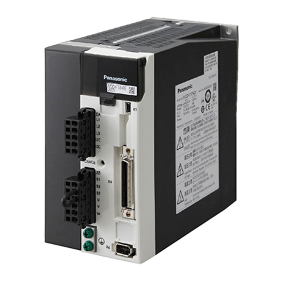
* This product image is 1.5 kW type of A5E-series.
If you are the first user of this product, please be sure to read the downloaded
Operating Instructions (Overall) from our Web Site.
http://industrial.panasonic.com/ww/i_e/25000/motor_fa_e/motor_fa_e.html
Make sure to forward these Operating Instructions for safety to the final user.
<Contents>
1. Introduction ................................. B2
On Opening the Product Package .................. B2
Check of the Driver Model .............................. B2
Check of the Motor Model............................... B3
2. Installation................................... B4
Driver .............................................................. B4
Motor . .............................................................. B6
Overall Wiring (Connector type) ..................... B8
Overall Wiring (Terminal block type) .................B12
Wiring of the Main Circuit (Connector type)......... B16
Wiring method to connector ............................. B19
Wiring Diagram ............................................. B21
Wiring of connector for motor and brake ...... B23
Wiring to the Connector, X1 . ........................ B24
Wiring to the Connector, X4 . ........................ B25
Wiring to the Connector, X6 . ........................ B27
Wiring to the Connector, X7 . ........................ B28
Operating Instructions (Basic)
AC Servo Motor & Driver
MINAS A5E-series (A to F-frame)
[Web address of Panasonic Corporation]
page
• Thank you for purchasing this
Panasonic product.
• Before operating this product,
please read the instructions
carefully, and save this manual for
future use.
・This product is for industrial
equipment. Don't use this
product at general household.
4. Parameter .................................. B29
Outline / Setup / Connection . ........................ B29
Composition of Parameters .......................... B31
5. Protective Functions ................ B32
Protective Function (What Is Error Code ?) ...... B32
6. Maintenance and Inspections .... B34
Composition of Peripheral Equipments ........ B38
8. Built-in Holding Brake .............. B43
9. Dynamic Brake.......................... B45
Incremental Specifications, 20-bit . .............. B46
11. Specifications ......................... B48
After-Sale Service (Repair) .......... B50
page
Advertisement
Table of Contents

Related Manuals for Panasonic MINAS A5E Series


Summary of Contents for Panasonic MINAS A5E Series
-
Page 1: Table Of Contents
・This product is for industrial equipment. Don't use this product at general household. * This product image is 1.5 kW type of A5E-series. If you are the first user of this product, please be sure to read the downloaded Operating Instructions (Overall) from our Web Site. [Web address of Panasonic Corporation] http://industrial.panasonic.com/ww/i_e/25000/motor_fa_e/motor_fa_e.html Make sure to forward these Operating Instructions for safety to the final user. <Contents> page page 1. -
Page 2: Introduction
1. Introduction Check of the Motor Model 1. Introduction Contents of Name Plate On Opening the Product Package Model A C S E R V O M O T O R Rated input MDME102G1C Model No. Rated rotational speed voltage/current INPUT 3φAC 5.7 A • Make sure that the model is what you have ordered. -
Page 3: Installation
2. Installation 2. Installation Driver Driver Install the driver properly to avoid a breakdown or an accident. Mounting Direction and Spacing Installation Place • Reserve enough sur- rounding space for 1) Install the driver in a control panel enclosed in noncombustible material and placed indoor 100 mm Control panel where the product is not subjected to rain or direct sunlight. The products are not waterproof. -
Page 4: Motor
2. Installation 2. Installation Motor Motor Install the motor properly to avoid a breakdown or an accident. 2) Vertical mounting • Use the motor with oil seal (make-to-order in case of motor 750 W or less) when Installation Place mounting the motor with gear reducer to prevent the reducer oil/grease from enter- ing to the motor. Since the conditions of location affect a lot to the motor life, select a place 3) For the dimensions and mass of the product, which are necessary design data of which meets the conditions below. the mounting section, refer to the dimensional outline drawing on the Operating In- 1) Indoors, where the products are not subjected to rain or direct sun beam. The prod- structions (Overall) or the Delivery Specification. -
Page 5: System Configuration And Wiring
3. System Configuration and Wiring 3. System Configuration and Wiring Overall Wiring (Connector type) Overall Wiring (Connector type) Connecting Example of A to D-frame : High voltage PC (to be supplied by customer) Wiring to Connector, X7 • Wiring of Main Connector (XA) •... - Page 6 3. System Configuration and Wiring 3. System Configuration and Wiring Overall Wiring (Connector type) Overall Wiring (Connector type) Connecting Example of E-frame : High voltage PC (to be supplied by customer) Wiring to Connector, X7 • Wiring of Main Connector (XA) •...
-
Page 7: Overall Wiring (Terminal Block Type)
3. System Configuration and Wiring 3. System Configuration and Wiring Overall Wiring (Terminal block type) Overall Wiring (Terminal block type) Connecting Example of F-frame PC (to be supplied by customer) : High voltage • Wiring of Main Connector Mains • Apply the voltage designated on the nameplate from the Residual Circuit Breaker (MCCB) -
Page 8: Driver And List Of Applicable Peripheral Equipments
3. System Configuration and Wiring 3. System Configuration and Wiring Driver and List of Applicable Peripheral Equipments Driver and List of Applicable Peripheral Equipments Reference page Noise filter .......P.B39 “Composition of Peripheral Equipments” Crimp Diameter Rated Diameter Crimp Diameter and Diameter terminal Noise Surge Required Circuit operating... -
Page 9: Wiring Of The Main Circuit (Connector Type)
3. System Configuration and Wiring 3. System Configuration and Wiring Wiring of the Main Circuit (Connector type) Wiring of the Main Circuit (Connector type) A to D-frame, 100 V / 200 V type E-frame, 200 V type • Wiring should be performed by a specialist or an authorized personnel. • Wiring should be performed by a specialist or an authorized personnel. • Do not turn on the power until the wiring is completed. • Do not turn on the power until the wiring is completed. -
Page 10: Wiring Of The Main Circuit (Terminal Block Type)
3. System Configuration and Wiring 3. System Configuration and Wiring (Terminal block type) Wiring of the Main Circuit Wiring method to connector F-frame, 200 V type • Follow the procedures below for the wiring connection to the Connector XA , XB and XC . How to connect • Wiring should be performed by a specialist or an authorized personnel. • Do not turn on the power until the wiring is completed. 1. Peel off the insulation cover of the cable. 8 to 9 mm • Never touch the terminal to which high voltage is applied. There is a risk of electric • For single wire (Please obey the length in figure.) shock. -
Page 11: Wiring Diagram
3. System Configuration and Wiring 3. System Configuration and Wiring Wiring method to connector Wiring Diagram 2. Insert the cable to the connector in the following 2 methods. Compose the circuit so that the main circuit power will be shut off when an error occurs. (a) Insert the cable using the supplied handle lever. In Case of Single Phase, In Case of 3-Phase, (b) Insert the cable using a flat-blade screwdriver (Edge width: 3.0 to 3.5 mm). A to D-frame, 100 V / 200 V type A to D-frame, 200 V type Power supply Single phase, Power supply 3-phase, (a) Using handle lever... -
Page 12: Wiring Of Connector For Motor And Brake
3. System Configuration and Wiring 3. System Configuration and Wiring Wiring Diagram Wiring of connector for motor and brake Compose the circuit so that the main circuit power will be shut off when an error occurs. • When the motors of <MSME (50 W to 750 W)> are used, they are connected as shown below. In Case of 3-Phase, In Case of 3-Phase, E-frame, 200 V type F-frame, 200 V type... -
Page 13: Wiring To The Connector, X1
3. System Configuration and Wiring 3. System Configuration and Wiring Wiring to the connector, X1 Wiring to the connector, X4 This is used for USB connection to a personal computer. It is possible to change the Wiring Example of Position Control Mode parameter setting and perform monitoring. Connector Application Symbol Contents Pin No. VBUS Use for communication with personal D− computer. USB signal terminal D+ —... -
Page 14: Wiring To The Connector, X6
3. System Configuration and Wiring 3. System Configuration and Wiring Wiring to the connector, X4 Wiring to the connector, X6 Wiring Example of Internal Velocity Control Mode Connection to Encoder • In case of 20-bit incremental encoder MSMD 50 W to 750 W MHMD 200 W to 750 W White +5 V Black... -
Page 15: Wiring To The Connector, X7
3. System Configuration and Wiring 4. Parameter Wiring to the connector, X7 Outline / Setup / Connection The connector X7 of the front panel is for monitor output. Outline of Parameter Analogue output : 2 systems This driver is equipped with various parameters to set up its characteristics and func- In both cases, it is possible to switch the output signal by setting parameters. tions. This section describes the function and purpose of each parameter. Read and comprehend very well so that you can adjust this driver in optimum condition for your Output circuit running requirements. Connector X7 1 kΩ AM1 • You can refer and set up the parameter with either one of the following. Manufacturer’s part No.: Measuring 1 kΩ... -
Page 16: Composition Of Parameters
4. Parameter 4. Parameter Outline / Setup / Connection Composition of Parameters Setup with the PC • The parameter No. is displayed in the form of PrX.YY (X: Classification, YY: No.). • For the details on the parameters, refer to the Operating Instructions (Overall). It is possible to connect your personal computer to connector X1 of MINAS A5E using a USB cable for personal computer connection. Downloading the setup support soft- Parametr No. -
Page 17: Protective Functions
5. Protective Functions 5. Protective Functions Protective Function (What Is Error Code ?) Protective Function (What Is Error Code ?) • Various protective functions are equipped in the driver. When these are triggered, the Error code Attribute Protective function motor will stall due to error, the driver will turn the Servo-Alarm output (ALM) to off (open). Main Sub History Can be cleared Immediate stop... -
Page 18: Maintenance And Inspections
6. Maintenance and Inspections 6. Maintenance and Inspections Maintenance and Inspections Maintenance and Inspections • Routine maintenance and inspection of the driver and motor are essential for Guideline for Parts Replacement the proper and safe operation. Use the table below for a reference. Parts replacement cycle varies depending on the actual operating conditions. Defective parts should be replaced or repaired when any Notes on Maintenance and Inspection error have occurred. -
Page 19: Conformity To Ec Directives And Ul Standards
Confirm that the effective current of the driver does not exceed the IEC : International Electrotechnical Commission : Europaischen Normen rated current. Set up the peak permissible current with Pr0.13 (Setup of 1st torque EMC : Electromagnetic Compatibility limit) and Pr5.22 (Setup 2nd torque limit). : Underwriters Laboratories (4) Motor over-temperature protection is not provided. CSA : Canadian Standards Association Motor over-load-temperature protection shall be provided at the final installation Pursuant to the directive 2004/108/EC, article 9(2) Panasonic Testing Centre upon required by the NEC (National Electric Code). Panasonic Service Europe, a division of Panasonic Marketing Europe GmbH Winsbergring 15, 22525 Hamburg, F.R. Germany − B36 − − B37 −... -
Page 20: Composition Of Peripheral Equipments
7. Conformity to EC Directives and UL Standards 7. Conformity to EC Directives and UL Standards Composition of Peripheral Equipments Composition of Peripheral Equipments Installation Environment Noise Filter Use the servo driver in the environment of Pollution Degree 1 or 2 prescribed in IEC- When you install one noise filter at the power supply for multi-axes application, consult with 60664-1 (e.g. Install the driver in control panel with IP54 protection structure.) manufacturer of the noise filter. If sufficient noise margin is required, connect 2 filters in series. • Optional parts Metallic control box Driver Voltage specifications Manufacturer’s Applicable Power... - Page 21 7. Conformity to EC Directives and UL Standards 7. Conformity to EC Directives and UL Standards Composition of Peripheral Equipments Composition of Peripheral Equipments Surge Absorber Voltage specifications Manufacturer’s Applicable Option part No. Manufacturer for driver part No. driver (frame) Provide a surge absorber for the primary side of noise filter.
-
Page 22: Built-In Holding Brake
8. Built-in Holding Brake 7. Conformity to EC Directives and UL Standards Composition of Peripheral Equipments Outline / Specifications Noise Filter for Signal Lines In the applications where the motor drives the vertical axis, this brake would be used to hold and prevent the work (moving load) from falling by gravity while the power to Install noise filters for signal lines to all cables (power cable, motor cable, encoder the servo is shut off. -
Page 23: Dynamic Brake
9. Dynamic Brake 8. Built-in Holding Brake Outline / Specifications Outline Specifications of Built-in Holding Brake This driver is equipped with a dynamic brake for emergency stop. Pay a special attention to the followings. Static Exciting Permissible Rotor Engaging Releasing Permissible Permissible Motor... -
Page 24: Check Of The Combination Of The Driver And The Motor
10. Check of the Combination of the Driver and the Motor 10. Check of the Combination of the Driver and the Motor Incremental Specifications, 20-bit Incremental Specifications, 20-bit This driver is designed to be used in a combination with the motor which are specified Motor Driver Power Rated rotational Rated by us. Check the series name of the motor, rated output torque, voltage specifications Type Model Model Frame supply speed output... -
Page 25: Specifications
11. Specifications 11. Specifications Basic Specifications Functions + 10 % (1) Deviation counter clear (2) Command pulse inhibition Main circuit Single phase, 100 to 120 V 50/60 Hz Control input (3) Command dividing gradual increase switching − 15 % 100 V (4) Damping control switching etc. + 10 % Control circuit Single phase, 100 to 120 V 50/60 Hz Control output Positioning complete (In-position) etc. − 15 % Max. command Exclusive interface for Photo-coupler: 500 kpps + 10 % A to Single/3-phase, 200 to 240 V 50/60 Hz pulse frequency Exclusive interface for line driver : 4 Mpps D-frame − 15 % Main Input pulse circuit... -
Page 26: After-Sale Service (Repair)
• This product is intended to be used with a general industrial product, but not de- Technical information of this product (Operating Instructions, CAD data) can be signed or manufactured to be used in a machine or system that may cause personal downloaded from the following web site. death when it is failed. http://industrial.panasonic.com/ww/i_e/25000/motor_fa_e/motor_fa_e.html • Installation, wiring, operation, maintenance, etc., of the equipment should be done by qualified and experienced personnel. • Apply adequate tightening torque to the product mounting screw by taking into consideration strength of the screw and the characteristics of material to which the product is installed. Overtightening can damage the screw and/or material; under- tightening can result in loosening. -
Page 27: Ime03+B
7-1-1 Morofuku, Daito, Osaka, 574-0044, Japan Phone : +81-72-871-1212 © Panasonic Corporation 2009 IME03+B Printed in China Z0110-3043...