Sign In
Upload
Manuals
Brands
Sony Manuals
TV
KV-29DRC420
Sony KV-29DRC420 Manuals
Manuals and User Guides for Sony KV-29DRC420. We have
2
Sony KV-29DRC420 manuals available for free PDF download: Service Manual
Sony KV-29DRC420 Service Manual (213 pages)
COLOR TELEVISION
Brand:
Sony
| Category:
TV
| Size: 18.65 MB
Table of Contents
Table of Contents
3
Service Manual
1
Section Title
3
Table of Contents
3
Specifi Cations
4
Warnings and Cautions
6
Safety Check-Out
7
Self-Diagnostic Function
8
Section 1: Disassembly
11
Rear Cover Removal
11
Chassis Assembly Removal
11
Service Position
11
Picture Tube Removal
12
Anode Cap Removal Procedure
12
Section 2: Set-Up Adjustments
13
Beam Landing
13
V-PIN and V-CEN Adjustment
14
Convergence
14
2-3.1. Vertical and Horizontal Static Convergence
14
2-3.2. Operation of BMC (Hexapole) Magnet
14
2-3.3. TLH Plate Adjustment
14
2-3.4. Screen-Corner Convergence
15
2-3.5. Dynamic Convergence Adjustments
15
Focus Adjustment
16
2-4.1. Dynamic Focus/Dynamic Quadra-Pole Data
16
Screen (G2)
17
Picture Quality Adjustments
17
2-6.1. Video Input - Sub Contrast Adjustment
17
2-6.2. Video Input - Sub Hue/Sub Color Adjustment
18
2-6.3. RF Input - Sub Contrast Adjustment
18
2-6.4. RF Input - Sub Hue/Sub Color Adjustment
19
White Balance (CRT) and Sub Bright Adjustment
19
2-7.1. Color Offset Adjustment Procedure
19
H Raster Center Adjustment
20
Picture Distortion Adjustments
20
2-9.1. NTSC (DRC) Full Mode Adjustment
20
2-9.2. 1080I HD Mode Adjustment
21
2-9.3. Vertical Compressed Mode Check and Confi Rmation
21
(For 4X3 CRT Only)
21
Section 3: Safety Related Adjustments
22
Preparation before Confi Rmation
22
3-1.1 Hold-Down Operation Confi Rmation
22
B+ Max Confi Rmation
22
B+ Voltage Check
22
High Voltage (HV) Check
22
Preparation for HV and Ik Protector Check
22
HV Protector Check
22
Cut off Condition
22
High Light Condition
23
IK Protector Check
23
Hold down Check
23
Restoration
23
HV Service Flowchart
24
3-10.1. HV Service Flowchart Table
25
Section 4: Circuit Adjustments
26
Setting Service Adjustment Mode
26
4-1.1. Service Adjustment Mode in
26
4-1.2. Service Adjustment Mode Memory
26
4-1.3. Reading the Memory
26
4-1.4. Adjusting the Picture
26
4-1.5. Resetting the Data
26
4-1.6. Resetting the MID NVM Data
26
4-1.7. Resetting the System NVM Data
26
4-1.8. Copy Function
26
Memory Write Confi Rmation Method
27
Remote Adjustment Buttons and Indicators
27
Service Data
28
ID Map Table
51
Section 5: Diagrams
52
Circuit Boards Location
52
Printed Wiring Boards and Schematic Diagrams Information
52
Block Diagrams
53
DZ Board Schematic Diagram (1 of 2)
56
Schematics and Supporting Information
56
DZ Board Schematic Diagram (2 of 2)
57
UY Board Schematic Diagram
60
HBY Board Schematic Diagram
61
AY Board Schematic Diagram (1 of 2)
64
AY Board Schematic Diagram (2 of 2)
65
HCX Board Schematic Diagram
68
CH Board Schematic Diagram
70
HAX Board Schematic Diagram
72
WY Board Schematic Diagram
73
BY Board Schematic Diagram (1 of 4)
75
BY Board Schematic Diagram (2 of 4)
76
BY Board Schematic Diagram (3 of 4)
77
BY Board Schematic Diagram (4 of 4)
78
MY Board Schematic Diagram (1 of 4)
79
MY Board Schematic Diagram (2 of 4)
80
MY Board Schematic Diagram (3 of 4)
81
MY Board Schematic Diagram (4 of 4)
82
P Board Schematic Diagram
85
Semiconductors (1 of 2)
86
Semiconductors (2 of 2)
87
Section 6: Exploded Views
88
Chassis (KV-27HS420/29DRC420)
88
Picture Tube (KV-27HS420/29DRC420)
89
Chassis (KV-30HS420/34HS420)
90
Picture Tube (KV-30HS420/34HS420)
91
Chassis (KV-32HS420/36HS420)
92
Picture Tube (KV-32HS420/36HS420)
93
Section 7: Electrical Parts List
94
Important Safeguards
143
Table of Contents
146
Overview
148
Introducing the Fd Trinitron Wega
148
Presenting the FD Trinitron Wega
148
Package Contents
148
Features
148
Setting up the TV
150
Overview
150
About the AC Power Cord
150
Setting up the Tv
150
TV Controls and Connectors
151
Front Panel
151
Rear Panel
152
Basic Connections: Connecting a Cable or Antenna
153
Cable, Cable Box, or Antenna Only
153
Connecting Optional Equipment
155
Making Video Connections
156
About Using S VIDEO
156
VCR and Cable
157
VCR and Cable Box
159
Two Vcrs for Tape Editing
161
Satellite Receiver
162
Satellite Receiver and VCR
163
DVD Player with Component Video Connectors
165
DVD Player with S VIDEO and Audio Connectors
167
DVI-Equipped Device
168
HDMI-Equipped Device
169
Camcorder
170
Audio Receiver
171
Using the CONTROL S Feature
172
Setting up the Channel List
173
Using Auto Program
173
Overview
174
Using the Remote Control
174
Inserting Batteries
174
Button Descriptions
175
Programming the Remote Control
178
Using the Features
180
Overview
180
Watching TV
180
Using Screen Mode
181
Models KV-30/34HS420 Only
181
Models KV-27/32/36HS420 Only
182
Using Favorite Channels
183
Creating a List of Favorite Channels
183
Displaying a List of Favorite Channels
183
Using Other Equipment with Your TV Remote Control
184
All Equipment
184
Operating a VCR
184
Operating a Satellite Receiver
184
Operating a Cable Box
185
Operating a DVD Player
185
Operating a DVD/VCR Combination Unit
185
Navigating through Menus
186
Using the Menus
186
Overview
186
Using the Video Menu
187
Selecting Video Options
187
Using the Audio Menu
189
Selecting Audio Options
189
Using the Screen Menu
191
Selecting Screen Mode Options
191
Using the Channel Menu
193
Selecting Channel Options
193
Using the Parent Menu
195
US Models: Selecting Custom Rating Options
196
Viewing Blocked Programs
196
Canadian Models: Selecting Custom Rating Options
197
Viewing Blocked Programs
197
Using the Timer Menu
198
Using the Setup Menu
199
Selecting Setup Options
199
Glossary
203
Contacting Sony
204
Troubleshooting
204
Remote Control
204
Channels
205
Video
205
Audio
206
General
206
Specifications
207
Optional Accessories
208
Index
210
Advertisement
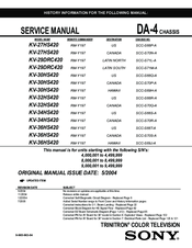
Sony KV-29DRC420 Service Manual (153 pages)
COLOR TELEVISION DA-4 CHASSIS TRINITRON series
Brand:
Sony
| Category:
TV
| Size: 14.8 MB
Table of Contents
Service Manual
1
Section Title
3
Table of Contents
3
Specifications
4
Warnings and Cautions
6
Safety Check-Out
7
Self-Diagnostic Function
8
Section 1: Disassembly
11
Rear Cover Removal
11
Chassis Assembly Removal
11
Service Position
11
Picture Tube Removal
12
Anode Cap Removal Procedure
12
Removal Procedures
12
Cable Wire Dressing
13
Side View
15
Section 2: Set-Up Adjustments
22
2-1. Beam Landing
22
V-PIN and V-CEN Adjustment
23
Convergence
23
2-3.1. Vertical and Horizontal Static Convergence
23
2-3.2. Operation of BMC (Hexapole) Magnet
23
2-3.3. TLH Plate Adjustment
23
2-3.4. Screen-Corner Convergence
24
2-3.5. Dynamic Convergence Adjustments
24
Focus Adjustment
25
2-4.1. Dynamic Focus/Dynamic Quadra-Pole Data
25
Screen (G2)
26
Picture Quality Adjustments
26
2-6.1. Video Input - Sub Contrast Adjustment
26
2-6.2. Video Input - Sub Hue/Sub Color Adjustment
27
2-6.3. RF Input - Sub Contrast Adjustment
27
2-6.4. RF Input - Sub Hue/Sub Color Adjustment
28
White Balance (CRT) and Sub Bright Adjustment
28
2-7.1. Color Offset Adjustment Procedure
28
H Raster Center Adjustment
29
Picture Distortion Adjustments
29
2-9.1. NTSC (DRC) Full Mode Adjustment
29
2-9.2. 1080I HD Mode Adjustment
30
2-9.3. Vertical Compressed Mode Check and Confirmation (for 4X3 CRT Only)
30
2-9.4 Normal, Zoom and Wide Zoom Modes
30
Section 3: Safety Related Adjustments
31
Preparation before Confirmation
31
3-1.1 Hold-Down Operation Confirmation
31
B+ Max Confirmation
31
B+ Voltage Check
31
High Voltage (HV) Check
31
Preparation for HV and Ik Protector Check
31
HV Protector Check
31
3-6-1. Cut off Condition
31
3-6-2. High Light Condition
32
Ik Protector Check
32
Hold down Check
32
Restoration
32
HV Service Flowchart
33
HV Service Flowchart Table
34
Electrical Adjustments by Remote Commander
35
Setting Service Adjustment Mode
35
4-1.1. Service Adjustment Mode in
35
4-1.2.Service Adjustment Mode Memory
35
4-1.3. Reading the Memory
35
4-1.4. Adjusting the Picture
35
4-1.5. Resetting the Data
35
4-1.6. Resetting the MID NVM Data
35
4-1.7. Resetting the System NVM Data
35
Memory Write Confirmation Method
36
Remote Adjustment Buttons and Indicators
36
Service Data
37
ID Map Table
60
Section 4: Circuit Adjustments
35
Section 5: Diagrams
61
Circuit Boards Location
61
Printed Wiring Boards and Schematic Diagrams Information
61
Reference Information
61
5-3. Block Diagrams
62
Schematics and Supporting Information
65
DZ Board Schematic Diagram (1 of 2)
65
DZ Board Schematic Diagram (2 of 2)
66
UY Board Schematic Diagram
69
HBY Board Schematic Diagram
70
AY Board Schematic Diagram (1 of 2)
73
AY Board Schematic Diagram (2 of 2)
74
HCX Board Schematic Diagram
77
CH Board Schematic Diagram
79
HAX Board Schematic Diagram
81
WY Board Schematic Diagram
82
BY Board Schematic Diagram (1 of 4)
84
BY Board Schematic Diagram (2 of 4)
85
BY Board Schematic Diagram (3 of 4)
86
BY Board Schematic Diagram (4 of 4)
87
MY Board Schematic Diagram (1 of 4)
88
Video Processor
88
MY Board Schematic Diagram (2 of 4)
89
MY Board Schematic Diagram (3 of 4)
90
MY Board Schematic Diagram (4 of 4)
91
P Board Schematic Diagram
94
PA Board Schematic Diagram
95
Semiconductors (1 of 2)
96
Semiconductors (2 of 2)
97
Section 6: Exploded Views
98
Chassis (KV-27HS420/29DRC420)
98
Picture Tube (KV-27HS420/29DRC420)
99
Chassis (KV-30HS420/34HS420)
100
Picture Tube (KV-30HS420/34HS420)
101
Chassis (KV-32HS420/36HS420)
102
Picture Tube (KV-32HS420/36HS420)
103
Section 7: Electrical Parts List
104
Advertisement
Related Products
Sony TRINITRON KV-29DRC430
Sony FD Trinitron KV-29CL11K
Sony Trinitron KV-29RS10C
Sony TRINITRON KV-29XL40M
Sony TRINITRON KV-29FX11D
Sony Trinitron KV-29FX20B
Sony KV-29K1D
Sony Trinitron KV-29VX2
Sony KV-29K1K
Sony Trinitron KV-29XL70E
Sony Categories
Laptop
TV
Camcorder
CD Player
Digital Camera
More Sony Manuals
Login
Sign In
OR
Sign in with Facebook
Sign in with Google
Upload manual
Upload from disk
Upload from URL