Sign In
Upload
Manuals
Brands
Siemens Manuals
Control Unit
LMS14
Siemens LMS14 Manuals
Manuals and User Guides for Siemens LMS14. We have
1
Siemens LMS14 manual available for free PDF download: User Manual
Siemens LMS14 User Manual (617 pages)
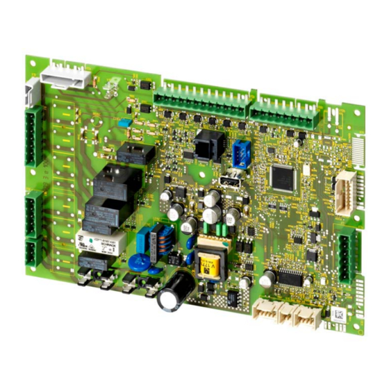
Albatros2 Boiler management unit
Brand:
Siemens
| Category:
Control Unit
| Size: 4.59 MB
Table of Contents
Table of Contents
3
1 Summary
13
Supplementary Documentation
13
Target Group of Users
14
Product Range Summary
15
Topology
15
Operating Options
16
2 Safety Notes
17
Notes on Product Liability
17
Use of High-Efficiency Pumps
18
High-Voltage Test
18
Environmental Compatibility
19
Lifecycle
19
Standards and Certificates
19
Typographical Conventions
20
Safety Notes
20
3 Mounting and Installation
21
Safety Regulations
21
Electrical Connection of Ionization Probe
21
Electrical Connection on 2-Phase Systems
22
Boiler Management Unit LMS14
23
Basic Diagram LMS14
25
Basic Unit LMS14
26
Terminals of LMS14
27
Assignment of Terminal X30
28
List of Terminals of LMS14
29
Basic Unit LMS14
30
Terminals of LMS14
31
Assignment of Terminal X30
32
List of Terminals of LMS14
33
Basic Unit LMS14
34
Terminals of LMS14
35
Assignment of Terminal X30
36
List of Terminals of LMS14
37
Cable Agu2.110X109
38
Parameter Stick Agu2.56Xx109
39
4 Commissioning
40
Basic Units
40
5 Handling
41
Operation and Display
41
Overview of Settings
42
6 The Settings in Detail
124
Time of Day and Date
124
Summer-/Wintertime Changeover
124
RF Link
125
Binding
125
List of Wireless Devices
126
Time Programs
128
Switching Points
128
Standard Program
128
Holidays
129
Heating Circuits
131
Operating Mode
131
Compensation Variants
132
Occupancy Button (Presence Button)
134
Operating Level
134
Setpoints
135
Heating Curve
136
ECO Function
139
Flow Temperature Setpoint Limits
142
Room Thermostat
143
Delay Heat Request
147
Room Model
149
Room Influence
150
Room Temperature Control and Limitation
152
Heating Limit Room Controller
152
Boost Heating
153
Quick Setback
154
Optimum Start/Stop Control
156
Heating up Gradient Room Model
157
Raising the Reduced Setpoint
157
Continuous Pump Operation
159
Frost Protection for the Room
160
Frost Protection for the Heating Circuit in Heating Mode
160
Overtemperature Protection for the Pump Heating Circuit
161
Locking Signals
162
Forced Signals
162
Overtemperature Protection for the Mixing Heating Circuit
162
Pulse Lock
163
Flow Temperature Alarm
163
Locking Signals
164
Forced Signals
164
Mixing Valve Control
165
Floor Curing Function
167
Forced Signal and Locking Signal
170
Buffer Storage Tank/Primary Controller
170
Speed-Controlled Pump
171
Operating Level Changeover Via Input H
174
Operating Mode Changeover Via Input H
174
Behavior in the Case of Burner Cycling
175
2-Speed Heating Circuit Pump
175
2-Speed Boiler Pump
176
Cooling Circuit 1
177
Operating Mode
177
Setpoints
177
Room Temperature Limitation
178
DHW Heating
179
DHW Mode
180
Setpoints
181
Holiday Program
182
DHW Release
183
Priority
185
Locking Signals
185
Forced Signals
185
Pump Overrun
186
Legionella Function
186
Circulating Pump
190
Frost Protection for the Circulation Pipe
191
Operating Mode Changeover Via Input H
192
Consumer Circuit and Swimming Pool Circuit
193
Swimming Pool
194
Setpoints
194
Priority
194
Overtemperature Protection
195
Plant Hydraulics
195
Primary Controller/System Pump
196
Limitations of the Flow Temperature Setpoint
196
Mixing Valve Control
197
Plant Hydraulics
198
Boiler
199
Release Threshold Outside Temperature
199
Full Charging of Buffer Storage Tank
199
Setpoints
200
Setpoint Manual Control
202
Frost Protection for the Boiler
203
PID Control Algorithm
204
Boiler/Burner Control
205
Overtemperature Protection
206
Minimum Limitation of Boiler Temperature
207
Minimum Limitation of Return Temperature
209
Boiler Pump
210
Electronic Temperature Controller
211
Limitation of Boiler Temperature Increase
212
Speed Control
214
Output Data
220
Fan
221
Controller Delay
223
Dynamic Switching Differentials
225
Delay Heat Request Special Operation
229
Flue Gas Supervision
230
Static Pressure Supervision
234
Dynamic Pressure Supervision
237
Water Pressure Sensor
241
Filling/Flow Supervision
243
Quick Shutdown of Burner
245
Limitation of Output
246
Electronic Limit Thermostat
248
Electronic Safety Limit Thermostat (SLT)
249
Energy Meter
255
Deaeration Function
256
Input Configuration Dynamic Pressure Supervision
258
Input Configuration Flow Supervision
258
Additional Settings for Static Pressure Supervision
259
Additional Settings for Dynamic Pressure Supervision
259
Special Boiler Functions
260
Change of Operating Mode
260
Loading the Setpoint/Actual Value
260
Automatic Heat Generation Lock
261
Manual Heat Generation Lock
261
Generation of Common Flow Temperature Setpoint
262
Generation of Boiler Temperature Setpoint
262
Boiler Control
263
Heat Output Limits
264
2-Position Controller
264
Protective Boiler Startup
265
Keeping the Boiler Hot
267
Alternative Setting of Output
267
Cascaded Systems
268
Addressing Devices
268
Cascade Master
269
Operating Mode
270
Control
271
Boiler Sequence
272
Minimum Limitation of Return Temperature
274
Supervision of Temperature Differential
275
Extra Heat Source
275
Solar
276
General
276
Sensors
277
Charging Controller (Dt)
279
Maximum Charging Temperature, Maximum Safety Temperature
281
Priority
282
Collector Start Function
284
Frost Protection for the Collector
286
Overtemperature Protection for the Collector
287
Recooling
289
Evaporation Temperature of Medium
291
Speed Control
292
Yield Measurement
293
Hours Run
293
Solid Fuel Boiler
294
General
294
Operating Mode
295
Setpoints
297
Control of the Boiler/Burner
298
Overtemperature Protection
302
Frost Protection
303
Frost Protection for the Solid Fuel Boiler
304
Configuration Errors
304
Sensor Error
304
Buffer Storage Tank
305
Release/Control of Heat Source
305
Automatic Locks
305
Charging Solar/Solid Fuel Boiler
307
Recooling
308
Plant Hydraulics
308
Return Diversion
309
Partial Charging
310
Full Charging
311
Frost Protection for the Buffer in Heating Mode
311
Heat Transfer to the DHW Storage Tank
312
DHW Storage Tank
314
Types of Heat Request
314
DHW Charging with One Sensor
314
DHW Charging with 2 Sensors
315
DHW Charging with Thermostat
315
Release
316
Charging Control
318
Limitation of Charging Time
319
Charging Pump/Diverting Valve
319
Discharging Protection
320
Overtemperature Protection
321
Frost Protection for the DHW Storage Tank
321
Recooling
322
Electric Immersion Heater
323
DHW Push
326
Excess Heat Draw
328
Plant Hydraulics
328
Speed-Controlled Pump
329
Heat Transfer
331
Stratification Storage Tank/Intermediate Circuit
332
Storage Tank Systems
334
Control of Storage Tank with Sensor
334
Stratification Storage Tank
336
Stratification Storage Tank with Control to the Boiler Temperature Flow
338
Full Charging of Stratification Storage Tank
340
Recharging the Stratification Storage Tank
341
Stratification Storage Tank with Control to the DHW Charging Temperature Via Setpoint Compensation
342
Full Charging of Stratification Storage Tank
344
Recharging the Stratification Storage Tank
347
Stratification Storage Tank with Direct Control to the DHW Charging Temperature
348
Full Charging of Stratification Storage Tank
349
Recharging the Stratification Storage Tank
351
Instantaneous Water Heater
352
Control
352
DHW Consumption (Flow)
352
DHW Consumption (Gradient)
353
Keep Hot Function
354
Times
355
Overrun
355
Speed-Controlled Pump
356
Configuration
357
Setpoint Readjustment
370
Configuration
378
Manual Setting/Adaption of Partial Diagrams
381
Heating Circuits/Cooling Circuit
381
DHW Storage Tank
382
DHW Separate Circuit
385
Boiler
388
Boiler Pump
390
Solar
395
Combi Storage Tanks
396
Relay Outputs QX
397
Sensor Inputs BX
403
Inputs H1/H3/H4/H5/H6/H7
405
Extension Modules
414
EX Extension Modules 1/2/3
416
QX Extension Modules 1/2/3
418
BX Extension Modules
423
H2 Extension Modules 1/2/3
425
PWM Output/10 V Output UX2/UX3
433
PWM Output P1
435
Types of Sensors/Readjustments
436
Building Model
437
Setpoint Compensation
439
Frost Protection for the Plant
440
Control of Flue Gas Damper
441
Pump/Valve Kick
441
Pressure Measurements H1, H2 and H3
442
Saving the Sensors
444
Plant Diagrams
463
Device Data
467
External Space Heating
468
Partial Diagrams
469
LPB System
470
Address/Power Supply
470
Errors/Maintenance/Alarm
472
Central Functions
473
Clock
478
Outside Temperature
478
Faults
479
Message
479
Acknowledgements
479
Error Message Functions
480
History
483
Maintenance/Special Mode
484
Maintenance Functions
484
Special Operating Modes
485
Parameter Stick AGU2.56
493
Wrong Use and Risks
493
Checks Made by the LMS14
493
Examples of Potential Risks
494
Reducing Potential Risks
494
Spare Part Business
495
General Notes on Risks and Problems
496
Operation Via the Boiler
497
Parameter Setting State
501
Conditions for the Transfer of Data between LMS14
502
Input/Output Test
504
Output Test Relay
505
Input Test Sensors
508
Input Test H1/H2/H3/H4/H5/H6/H7
509
Input Test EX (Extension Modules)
509
Operating State
510
Messages
510
Diagnostics of Cascaded System
515
Diagnostics of Heat Sources
516
Process Values
516
Diagnostics of Consumers
517
Burner Control
518
Prepurging
518
Ignition
519
Operation
520
Postpurging
521
Configuration
522
Fan Control
525
Chimney Drying
526
Setpoint Filter for Fan Speed Control
527
Configuration
531
Program Sequence of Burner Control (Function)
535
Program Selection
535
Forced Intermittent Operation
535
Burner Control Program
535
Burner Capacities
536
Sequence Diagram for Burner Capacities ≤120 Kw and Release QAA Fan Param [4337.1] = on
537
Sequence Diagram for Burner Capacities >120 Kw and Release QAA Fan Param [4337.1] = on
538
Sequence Diagram for Burner Capacities ≤120 Kw and Release QAA Fan Param [4337.1] = off
539
Sequence Diagram for Burner Capacities >120 Kw and Release QAA Fan Param [4337.1] = off >120 Kw
540
Repetition Counter
544
Description of Sequence Diagrams
545
Fan Speed Control
551
Filter for Fan Speed Setpoint (OEM)
552
PWM Limitation
556
Supervising Air Supply by Monitoring Current Fan Speed
556
Chimney Drying
558
Fan Parameters Settable as Load Values Via QAA75
559
Limitation of Ionization Current
566
Ionization Current Maintenance
567
Modulating Pump
568
Modulation of Heating Circuit Pump
568
Behavior When Burner Cycles
570
Limitation of Boiler Temperature Differential
571
Conditions for Limiting the Boiler's Temperature Differential
572
Limitation Dependent on Pump Modulation
572
Limitation to the Maximum Differential
573
Limitation to the Nominal Differential
574
List of Displays
575
Error Code List
575
Maintenance Code
578
Lockout/Local Reset
579
Lockout
579
Local Reset Via the Reset Button
579
Remote Reset
580
Additional Activation of Remote Reset Capability
580
Restrictions in Connection with Remote Reset
580
Production
581
Monitoring Mains Voltage/Mains Frequency
583
7 Plant Diagrams
584
Basic Diagrams
584
Extra Functions
585
8 Technical Data
586
Lms14
586
General Data
586
Environmental Conditions
586
Electrical Connection Data, Mains Voltage Connections
587
Electrical Connection Data, Extra-Low Voltage Connections (PELV)
589
Inputs B7/BX4
589
Inputs B3/B38
590
Inputs BX1/BX2/BX3
590
Input B9
590
Input H1
590
Input H3
591
Input H4
591
Input H5
591
Input H6
592
Input H7
592
Input for Reset (EK)
592
PWM Fan/Hall Connection Facility
592
PWM Pump Connection P1
593
PWM Output/10 V Output UX2/UX3
593
Control of Diverting Valve
593
BSB Users
594
Outputs for LED Flame and LED Fault (X30)
594
Cross-Sectional Area Sensors
594
Parameter Stick Agu2.56Xx109
595
Sensor Characteristics
596
NTC 1K
596
NTC 10K
597
Pt1000
597
NTC 20K
598
9 List of Figures
599
Advertisement
Advertisement
Related Products
Siemens LME11 series
Siemens LME22 series
Siemens LME44 series
Siemens LMV51 Series
Siemens LMV52.200B1
Siemens LMV52.440B1
Siemens LMO24 Series
Siemens LMO44 Series
Siemens LMO24.111C2
Siemens LMO44.255C2
Siemens Categories
Industrial Equipment
Controller
Control Unit
Oven
Washer
More Siemens Manuals
Login
Sign In
OR
Sign in with Facebook
Sign in with Google
Upload manual
Upload from disk
Upload from URL