Sign In
Upload
Manuals
Brands
Philips Manuals
Micro Music System
FW-C380/21
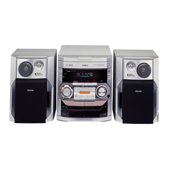
Philips FW-C380/21 Manuals
Manuals and User Guides for Philips FW-C380/21. We have
1
Philips FW-C380/21 manual available for free PDF download: Service Manual
Philips FW-C380/21 Service Manual (105 pages)
Mini System
Brand:
Philips
| Category:
Micro Music System
| Size: 25.16 MB
Table of Contents
Table of Contents
1
Location of Printed Boards
2
Specifications
3
Measurement Setup
4
Service Aids
5
Handling Chip Components
5
Warning
6
Contents
7
Product View
7
Preparations
8
Safety Information
8
Rear Connections
8
General Information
8
Controls
9
Inserting Batteries into the Remote Control
9
Subwoofer out Connection
9
Digital out Connection
9
To Reinstall the Plug and Play
10
Operating the System
10
If the Plug and Play Has Not Been Installed
10
Plug and Play
10
Demonstration Mode
11
Switching the System on
11
Switching the System to Standby Mode
11
Selecting the Source
11
Compact Disc
12
Virtual Environment Control (VIC)
12
Dynamic Bass Boost (DBB)
12
Optimal Sound MIX
12
Playing a Disc
13
Disc Change
13
Programming Tracks
13
Shuffle
13
Receiving RDS Radio Station
14
Storing Preset Stations
14
Tuning to Radio Stations
14
Tuner
14
RDS Clock
15
Loading a Tape
15
Tape Playback
15
To Start/Cancel News Function
15
Selecting External Equipment
16
One Touch Recording
16
Rewind/Fast Forward
16
Recording
16
CD Synchro Start Recording
17
Dubbing Tapes
17
Recording from Other Sources
17
Clock/Timer
17
Maintenance
18
Troubleshooting
18
Sleep Timer
18
Cleaning
18
Changing the MW Tuning Grid
20
Additional Features
20
Microphone Mixing
20
Karaoke
20
Dismantling of the Cassette Cover
21
Dismantling of the CDC Module and Front Panel
21
Dismantling of the Front Board
22
Dismantling of the ETF Tape Module
22
Dismantling of Rear Portion
22
Repair Hints
22
Service Test Program
24
Set Block Diagram
25
Set Wiring Diagram
26
Front Board
27
FTD Display Pin Connections
27
Front Board - Component Layout
28
Front Board - Chip Layout
29
Front Board - Circuit Diagram
30
Key-CDC Part - Circuit Diagram
31
Key-CDC Board - Component Layout
31
Front Board Variation Table
31
Headphone Board - Component Layout
32
Headphone Board - Chip Layout
32
Karaoke Board - Component Layout/Chip Layout
32
Headphone Part - Circuit Diagram
32
Karaoke Part - Circuit Diagram
33
Electrical Parts List
34
Block Diagram
37
Tuner Adjustment Table
39
Tuner Board ECO6 View
39
Electrical Parts List ECO6
40
ECO6 Tuner Board Block Diagram
41
ETF7 Tape Module (Non-Dolby Version)
45
Tapedeck Wiring (Double Deck)
45
Variations Table for Analog Circuit
45
Brief Introduction
47
Notations and Abbreviations
47
Connectors Assignments
48
Tape Mechanism Electronics
49
Tape Adjustment and Check Table
49
Component Layout
50
Chip Layout
50
Analog Circuit
51
Servo Control Unit
52
Tape Module Exploded View
53
Tape Mechanism - Motor Exploded View
53
Play Mechanism Exploded View
54
Record/Playback Mechanism Exploded View
55
Electrical Parts List - ETF7 Non-Dolby Board
57
3CDC-LC - 3 Disc Carrousel Changer
59
Steps Have to be Done When Replacing the CD Mechanism
60
Service Position
61
Wiring
62
3CDC-LC Block Diagram
63
3CDC-LC Main Board Views
64
3CDC-LC Main Board Diagram
65
3CDC-LC Module Exploded View
68
Drawer Bottom View
69
Drawer Top View
69
3CDC-LC Module Electrical Parts List
70
3CDC-LC-MB Module - 3 Disc Carousel Changer
73
3CDC-LC-MB Module - Mechanism Replacement
74
3CDC-LC-MB Service Position
75
3CDC-LC-MB Wiring
76
3CDC-LC-MB Block Diagram
77
3CDC-LC-MB Component Side View
78
3CDC-LC-MB Copper Side View
78
3CDC-LC-MB Diagram
79
3CDC-LC-MB Module Exploded View
82
Drawer Bottom/Top View
83
3CDC-LC-MB Module Electrical Parts List
84
Power 2001 Module - 30 - 70W Version
87
Power 2001 Module Circuit Detail
87
Generation of +C1
88
Power 2001 Module Block Diagram
89
Power 2001 Module Mains Board Views
90
P2001 30-70W Mains Diagram
91
Power Board Copperside View
92
P2001 30-70W Diagram
93
Power 2001 Module Electrical Parts List
94
Table of Contents
95
AF9 Board - Features
95
AF9 Board - Component Layout
96
AF9 Board - Chip Layout
97
AF9 Board - Circuit Diagram (Part 1)
98
AF9 Board - Circuit Diagram (Part 2)
99
Video out Cinch Boad Views
100
Video out Cinch Part Circuit Diagram
100
AF9 Board Electrical Parts List
100
Electrical Parts List
101
Set Mechanical Exploded View
103
Mechanical and Accessories Parts List - Main Unit
104
Screw List - Main Unit
104
Advertisement
Advertisement
Related Products
Philips FW-C380/22
Philips FW-C380/34
Philips FW-C380/37
Philips FW-C39922
Philips FW-C39937
Philips FW16/41
Philips FW16/41M
Philips FW16/21
Philips FW16/20
Philips FW16
Philips Categories
TV
Monitor
Stereo System
Electric Shaver
CD Player
More Philips Manuals
Login
Sign In
OR
Sign in with Facebook
Sign in with Google
Upload manual
Upload from disk
Upload from URL