Sign In
Upload
Manuals
Brands
Panasonic Manuals
Servo Drives
MINAS-A5BL Series
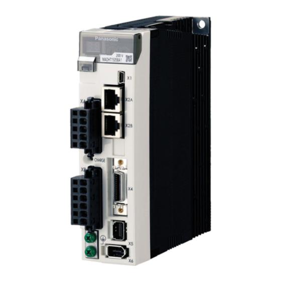
Panasonic MINAS-A5BL Series Manuals
Manuals and User Guides for Panasonic MINAS-A5BL Series. We have
1
Panasonic MINAS-A5BL Series manual available for free PDF download: Manual
Panasonic MINAS-A5BL Series Manual (206 pages)
Brand:
Panasonic
| Category:
Servo Drives
| Size: 4.26 MB
Table of Contents
22.Interface Specification
14
Table of Contents
14
I/O Connector Input Signal
15
I/O Connector Output Signal
17
I/O Connector Other Signal
21
Feedback Scale Output Signal
21
Others
21
I/O Signal Allocation Function
22
Input Signal Allocation
22
Class no
23
Title Unit Range
23
Assignment of Output Signal
26
.Front Panel Display Specification3
29
Appearance of Front Panel
30
7-Segment LED
31
Ethercat Indicators
34
Monitor Signal Output Function
36
Station Alias
39
44.Basic Function
40
Operation Direction Setup
41
Position Control
42
Process of Command Pulse Input
42
Electronic Gear Function
43
Positional Command Filtering Function
46
Positioning Complete Output (INP/INP2) Function
48
Pulse Regeneration Function (some Models Not Supported)
50
Attained Speed Output (AT-SPEED)
53
Velocity Control
53
Speed Coincidence Output (V-COIN)
54
Velocity Command Acceleration/Deceleration Setting Function
55
Speed Limit Function
57
Toruqe Control
57
Setting Regenerative Resistor
58
Absolute Setup
59
Feedback Scale
59
Linear Motor/Feedback Scale Setting
60
Parameter Setting According to Linear Motor/Feedback Scale Specification
61
Current Gain Setting
66
Pole Position Detection Method Setting
67
Automatic Linear Motor Setting with Tool
74
55.Gain Tuning/Vibration Suppressing Function
77
Automatic Adjusting Function
78
Real-Time Auto Tuning
79
00 1St Gain of Position
83
1St Filter of Velocity
83
1St Torque Filter Time
83
2Nd Filter of Velocity Detection
83
2Nd Gain of Position Loop
83
2Nd Torque Filter Time Constant
83
Detection
83
Torque Feed Forward Filter
83
Velocity Feed Forward Filter
83
Velocity Feed Forward Gain
83
2Nd Gain Setup
84
Control Switching
84
Delay Time of
84
Level of Position
84
Mode of Position
84
Position Control 0.1 Ms 0-10000 Switching
84
Adaptive Filter
87
Real-Time Auto Tuning (2 Degrees of Freedom Control Mode Standard Type)
90
Hysteresis at Position
95
Position Gain
95
Switching Time
95
Manual Adjusting Function
98
Block Diagram of Position Control Mode
99
Block Diagram of Velocity Control Mode
100
Block Diagram of Torque Control Mode
101
Gain Switching Function
102
Delay Time of
103
Level of Velocity
103
Mode of Velocity Control Switching
103
Velocity Control 0.1 Ms 0-10000 Switching
103
Notch Filter
108
Damping Control
110
Feed Forward Function
114
Instantaneous Velocity Observer Function
116
Disturbance Observer Function
118
3Rd Gain Switching Function
120
Friction Torque Compensation
121
2-Stage Torque Filter
123
Mode of 2 Degrees of Freedom Control (Standerd Type)
124
Model Type Damping Filter
127
Viscous Friction Compensating Gain / Model Type Damping Filter Application Parameter Switching Function
131
66.Application
133
Torque Limit Switching Function
134
Motor Working Range Setup Function
135
Deceleration Stop Sequence
137
Sequence Upon Inputting of Over-Travel Inhibition (POT, NOT) (under Review)
137
Sequence at Servo-Off
139
Sequence at Main Power off
140
Sequence at Alarm
142
Emergency Stop Upon Occurrence of Alarm
144
Torque Saturation Protection Function
146
77.Protective Function/Warning Function
147
List of Protective Function
148
Details of Protective Function
151
Warning Function
165
Setup of Gain Pre-Adjustment Protection
168
88. Safety Function
170
Outline Description of Safe Torque off (STO)
171
Safety Input/ Signal
172
Specifications of Input & Output Signals
172
External Device Monitor (EDM) Output Signal
173
Internal Signal Circuit Block Diagram
173
Detailed Functional Description
174
Operating Timing for Safety Status
174
Return Timing from Safety State
175
Example of Connection
176
Example of Connection to Safety Sensor
176
Example of Connection to Safety Switch
176
Example of Connection to Safety Controller
177
Example of Connection When Using Multiple Axes
178
Safety Precautions
179
99.Other
181
List of Parameters
182
Servo-On Signal Accept Timing on Power-Up: When Magnet Pole Position Estimation Is Valid (Pr 9.20 = 2)
198
Timing Chart
198
Servo-On Signal Accept Timing on Power-Up: When Magnet Pole Position Estimation Is Invalid (Pr 9.20 = 0, 1, 3)
200
Servo-ON/OFF Action While the Motor Is at Stall (Servo-Lock)
202
Servo-ON/OFF Action While the Motor Is in Motion
203
When an Error (Alarm) Has Occurred (at Servo-ON Command) (DB Deceleration,Free Run Deceleration Movement)
204
When an Error (Alarm) Has Occurred (at Servo-ON Command) (Emergency Stop Movement)
205
When an Alarm Has Been Cleared (at Servo-ON Command)
206
Advertisement
Advertisement
Related Products
Panasonic MINAS-A4N
Panasonic MINAS-A5NL Series
Panasonic MINAS-A5B Series
Panasonic MINAS-A6 Series
Panasonic MINAS-A6B Series
Panasonic MEDDT7364N
Panasonic MDDHT3530N91
Panasonic MHMD042P1C
Panasonic MEDLN83SE
Panasonic MEDL*83 Series
Panasonic Categories
Camcorder
Air Conditioner
TV
Digital Camera
Cordless Telephone
More Panasonic Manuals
Login
Sign In
OR
Sign in with Facebook
Sign in with Google
Upload manual
Upload from disk
Upload from URL