Sign In
Upload
Manuals
Brands
Panasonic Manuals
VCR
AJ-D455P
Panasonic AJ-D455P Manuals
Manuals and User Guides for Panasonic AJ-D455P. We have
2
Panasonic AJ-D455P manuals available for free PDF download: Service Manual, Operating Instructions Manual
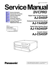
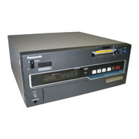
Panasonic AJ-D455P Service Manual (743 pages)
Digital Video Cassette Recorder/ Component Serial Interface Board/ Digital Video Interface Board/ Cassette Adapter
Brand:
Panasonic
| Category:
VCR
| Size: 76.05 MB
Table of Contents
Service Information
334
Table of Contents
334
1 Servicing Fixtures & Tools
335
2 Alignment Tape
338
VFM3580KM / L (NTSC) (25 M Adjustment Tape)
338
VFM3582KM / L (NTSC) (Manufacturer (X-Value) Adjustment Tape)
338
VFM3010EDS (NTSC) (DV Adjustment Tape)
338
VFM3000EDS (DV (LISTA) Adjustment Tape)
338
3 List of Recommended Measuring Instruments
339
4 Maintenance
340
Maintenance Schedule
340
Layout of the Maintenance Parts
341
Layout of the Other Parts
341
5 Manual Tape Eject(Emergency Eject)
342
6 Cylinder Head Cleaning Method
343
Cylinder Head Chips Cleaning Method: (Daily)
343
Cylinder Lead Cleaning Method: (Weekly)
343
A/C Head Cleaning Method: (Weekly)
343
Pinch Roller and Capstan Shaft Cleaning Method:(Weekly)
343
Post Cleaning Method: (Weekly)
343
7 Diag-Menu Display
344
DIAG-MENU Operation Method
344
Hour Meter Display
345
How to Reset the Hour Meter
345
8 Software Version Display
346
Version Display Operation Procedure
346
How to Read the Version Display
346
9 Software Version Upgrade Method
347
Version Upgrade for the SERVO Microcomputer with Built-In Flash Memory
347
E-PROM (SYSCON, IF, AV) Version Upgrade
349
PLD Version Upgrade Procedure
349
10 Error Rate Display and Confirmation Method
359
11 Internal Switch Setting Method
360
12 Internal LED Indication
360
13 Service Menu
361
Service Menu Operation Method
361
DEFAULT Operation
362
Service Menu Contents
363
SET-UP Menu Initialization
375
14 Notes on Removal of PCB F3A, F3B, F8
376
15 Circuit Board Layout Drawing
377
16 AJ-YAD455P Service Information
378
Node Unique ID (UID) Number Setting Procedure
378
Version Upgrade for Flash Memory
379
PLD Version Upgrade Procedure
382
Disassem Bly Procedures
386
Disassembly Procedures
387
Removal of Bottom Panel
387
Removal of Front Loading Unit
387
Removal of Front Panel Unit
387
Removal of Top Panel
387
Removal of Mechanism Unit
388
Removal of Cylinder Unit
389
Removal of Fan Motor
389
Removal of Power Supply Unit
389
Electrical Adjustment
390
1 Power Supply Unit
392
Power Supply Voltage Adjustment
392
2 Servo
392
SERVO FG Offset Adjustment
392
Reel Torque Gain Adjustment
393
Motor Torque Offset Adjustment
393
Tension Sensor Voltage Adjustment (1)
394
Tension Sensor Voltage Adjustment (2)
394
PG Shifter Adjustment
395
3 Rf/Eq (F8)
396
Adjustment Data Initialization
397
VCO Center Frequency Value Reading
397
Envelope Level Adjustment
398
Phase Compensation Adjustment
398
Confirmation of Error Rate and AEQ Tap Coefficient Values
399
REC Frequency Characteristic and REC Current Adjustment (DVCPRO 25M)
400
REC Frequency Characteristic and REC Current Adjustment (DV)
401
4 Out (F2)
402
Connection
402
Reference PLL Center Frequency Adjustment
403
Reference CF Detection Adjustment
403
Composite Sync DC Level Adjustment
404
Composite y Level Adjustment
404
Composite YC Timing Adjustment
405
Composite C Gain Adjustment
405
System Sub-Carrier Phase Adjustment
405
Component Sync DC Adjustment
406
Component y Level Adjustment
406
Component Pb Level Adjustment
409
Component Pr Level Adjustment
409
Component Y-Pb Timing Adjustment
409
Component Y-Pr Timing Adjustment
409
5 In (F5)
409
Connection and Menu Setting
410
DC Adjustment
411
Composite Color Demodulation Timing Adjustment
411
Composite SCH Detection Adjustment
411
Composite Color Demodulation Timing Adjustment
412
YC in SCH Detection Adjustment
412
Component y Signal Level Adjustment
413
Component y Signal Offset Level Adjustment
413
Component Pb Signal Offset Level Adjustment
414
Component Pr Signal Offset Level Adjustment
414
Component Pb Signal Level Adjustment
415
Component Pr Signal Level Adjustment
415
Component Pb Signal Timing Adjustment
416
Component Pr Signal Timing Adjustment
416
Composite y Signal Level Adjustment
417
Composite y Signal Offset Level Adjustment
417
Composite Pb Signal Offset Level Adjustment
418
Composite Pr Signal Offset Level Adjustment
418
Composite Pb Signal Level Adjustment
419
Composite Pr Signal Level Adjustment
419
Composite Pb/Pr Signal Timing Adjustment
420
Composite Video out Phase Adjustment
421
Composite Vector Adjustment
421
Y Signal Level (YC IN) Adjustment
422
Y Signal Offset Level (YC IN) Adjustment
422
Pb Signal Offset Level (YC IN) Adjustment
423
Pr Signal Offset Level (YC IN) Adjustment
423
Pb Signal Level (YC IN) Adjustment
424
Pr Signal Level (YC IN) Adjustment
424
Pb/Pr Signal Timing (YC IN) Adjustment
425
YC in Vector Adjustment
426
6 AUDIO (F1) and RF/CUE
427
Setting
427
CH1, CH2 Output Level Adjustment
427
CH1, CH2 Input Level Adjustment
427
CUE BIAS CURRENT Adjustment
428
CUE PB Level Adjustment
428
CUE REC/PB Level Adjustment
428
7 TP, VR, SW Location
429
DV Ucom
462
Rf/Cue (1/4)
570
Rf/Cue (2/4)
570
Rf/Cue (3/4)
571
Rf/Cue (4/4)
571
F8:Rf/Eq
574
Mother (1/10)
581
Mother (10/10)
581
Mecha_If (1/4)
589
Mecha If2
595
Power1
596
Power1 (2/2)
596
Power2
598
Power2 (1/1)
598
Av_Jack (Connector) (1/5)
599
Av_Jack (Bnc I/O) (2/5)
599
Av_Jack (Aes I/O) (4/5)
600
DV Ucom
604
DV U COM (1/1)
604
Front (Vfd) (2/3)
606
Front(Vr, Conector) (3/3)
607
Eject
609
Eject (1/1)
609
Dif Jack
610
Dif (Fpga Dram) (8/9)
610
Circuit Board Diagrams
620
F3A Sdi P.C. Board (Vep83558A)
625
Csp Sub P.C. Board (Vep83555A)
628
Rf Cue P.C. Board (Vep85197A)
635
F8 Rf Eq P.C. Board (Vep85196A)
636
Mecha if P.C. Board (Vep82239A)
639
Mecha If2 P.C. Board (Vep82240A)
640
Power1 P.C. Board (Vep81221A)
641
DV U COM P.C. BOARD (VEP83560A)
646
Hp P.C. Board (Vep80C15A)
646
Exploded Views & Replacement Parts List
649
Servicing Fixtures & Tools
650
Mechanical Chassis Assembly (1)
651
Mechanical Chassis Assembly (2)
652
Sub Chassis Assembly
655
Cassette Compartment Assembly
657
Casing Parts Assembly
659
Front Panel Assembly
661
Chassis Frame Assembly
663
Rear Panel Assembly
665
Packing Parts Assembly
667
Packing Parts Assembly (Aj-Ya455P)
668
Packing Parts Assembly (Aj-Yad455P)
669
Packing Parts Assembly (Aj-Cs455P)
670
Advertisement
Panasonic AJ-D455P Operating Instructions Manual (52 pages)
DVCPRO Digital Video Cassette Recorder
Brand:
Panasonic
| Category:
VCR
| Size: 0.34 MB
Table of Contents
Operating Instructions
1
Table of Contents
3
General and Features
4
Controls and Their Functions
6
Front Panel
6
Connector Area
11
Tapes
14
Setup (Default Settings)
15
Setup Menus
16
SYSTEM Menu
20
USER Menu
22
BASIC Menu
22
OPERATION Menu
25
INTERFACE Menu
26
EDIT Menu
28
TAPE PROTECT Menu
30
TIME CODE Menu
31
VIDEO Menu
33
AUDIO Menu
36
MENU Menu
37
Time Code
38
Time Code/User Bit
38
Recording Internal/External Time Codes
39
Reproducing the Time Code/User Bit
40
Superimpose Screen
41
Servo Reference
42
Rack Mounting
43
Video Head Cleaning
44
Condensation
44
Error Messages
45
Connector Signals
48
Printed Circuit Board
50
Specifications
51
Advertisement
Related Products
Panasonic AJD440 - DVCPRO PLAYER
Panasonic AJD450 - DVCPRO EDITOR
Panasonic AJ-D440P
Panasonic AJ-D450P
Panasonic AJ-D455
Panasonic AJD220P - DVC PRO
Panasonic AJ-D960
Panasonic AJ-D230P
Panasonic AJ-D780
Panasonic AJ-D850AP
Panasonic Categories
Camcorder
Air Conditioner
TV
Digital Camera
Cordless Telephone
More Panasonic Manuals
Login
Sign In
OR
Sign in with Facebook
Sign in with Google
Upload manual
Upload from disk
Upload from URL