Sign In
Upload
Manuals
Brands
Motorola Manuals
Portable Radio
PR860
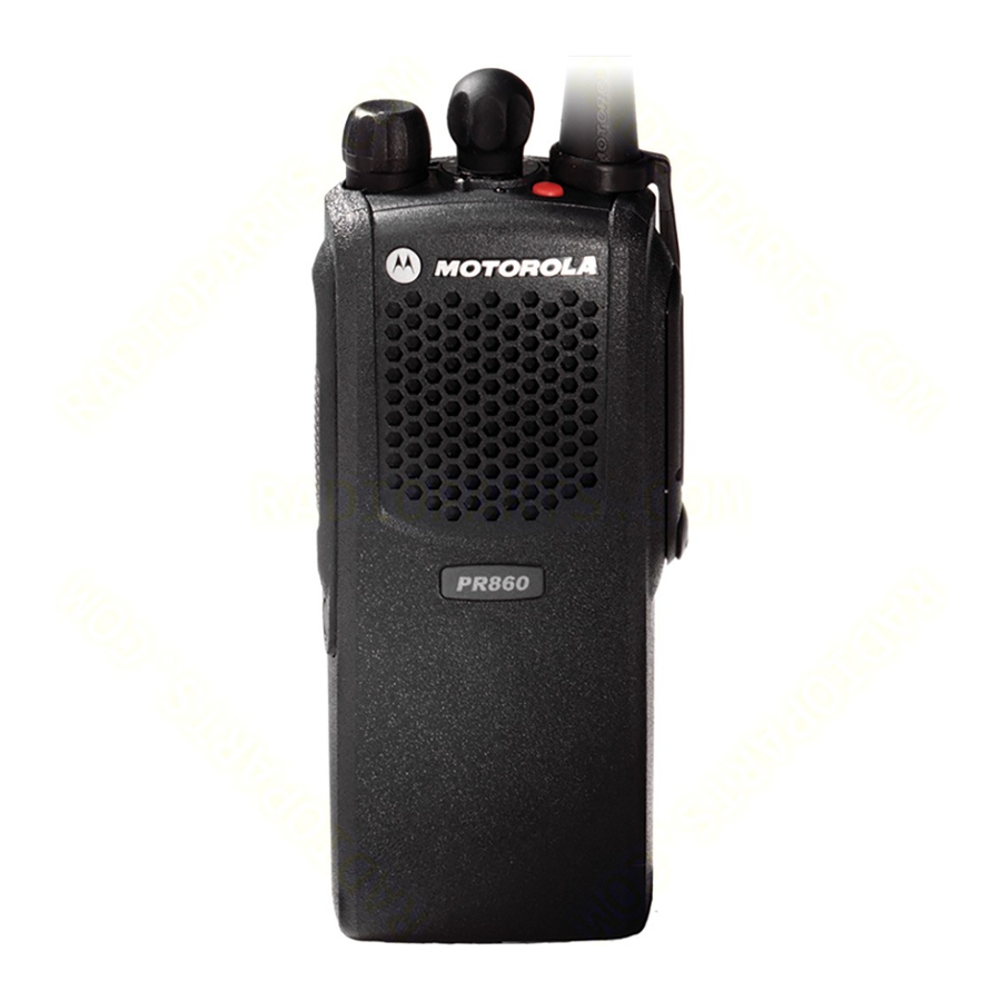
Motorola PR860 Manuals
Manuals and User Guides for Motorola PR860. We have
4
Motorola PR860 manuals available for free PDF download: Detailed Service Manual, Basic Service Manual, User Manual
Motorola PR860 Detailed Service Manual (197 pages)
Two-Way Portable Radio
Brand:
Motorola
| Category:
Two-Way Radio
| Size: 8.46 MB
Table of Contents
Foreword
3
Manual Revisions
3
Computer Software Copyrights
3
Document Copyrights
3
Disclaimer
3
Trademarks
3
Table of Contents
6
List of Figures
10
Chapter 1 Introduction
14
Scope of Manual
14
Warranty and Service Support
14
Warranty Period
14
Return Instructions
14
After Warranty Period
14
Related Documents
15
Technical Support
15
Piece Parts Availability
15
Radio Model Chart and Specifications
16
Radio Model Information
16
Chapter 2 Theory of Operation
18
Introduction
18
Radio Power Distribution
18
Figure 2-1. DC Power Distribution Block Diagram
18
Controller Board
20
MCU Digital
20
Figure 2-2. Controller Block Diagram
20
MODB/VSTBY Supply
21
Audio/Signaling
21
UHF1 Transmitter
21
Figure 2-3. Transmitter Block Diagram
21
Antenna Matching Network
22
Antenna Switch
22
Harmonic Filter
22
Power Amplifier (PA)
22
Power Control Integrated Circuit (PCIC)
22
Temperature Cut Back Circuit
23
UHF1 Receiver
23
Receiver Front-End
23
Figure 2-4. UHF Receiver Block Diagram
23
Receiver Back-End
24
Frequency Generation Circuit
25
Figure 2-5. Frequency Generation Unit Block Diagram
25
UHF1 Synthesizer
26
Figure 2-6. Uhfsynthesizer Block Diagram
26
UHF1 Voltage Control Oscillator (VCO)
27
Figure 2-7. UHF VCO Block Diagram
27
UHF2 Transmitter
28
Figure 2-8. Transmitter Block Diagram
28
Antenna Matching Network
29
Antenna Switch
29
Harmonic Filter
29
Power Amplifier (PA)
29
Power Control Integrated Circuit (PCIC)
29
UHF2 Receiver
30
Receiver Front-End
30
Figure 2-9. UHF Receiver Block Diagram
30
Receiver Back-End
31
Frequency Generation Circuit
31
Figure 2-10. Frequency Generation Unit Block Diagram
31
UHF2 Synthesizer
32
Figure 2-11. Synthesizer Block Diagram
33
UHF2 Voltage Controlled Oscillator (VCO)
34
Figure 2-12. VCO Block Diagram
34
VHF Transmitter
36
Power Amplifier
36
Antenna Switch
36
Figure 2-13. Transmitter Block Diagram
36
Harmonic Filter
37
Antenna Matching Network
37
Power Control Integrated Circuit (PCIC)
37
VHF Receiver
38
Receiver Front-End
38
Figure 2-14. VHF Receiver Block Diagram
38
Receiver Back-End
39
Automatic Gain Control (AGC)
39
Frequency Generation Circuit
40
VHF Synthesizer
40
Figure 2-15. Frequency Generation Unit Block Diagram
40
Figure 2-16. Synthesizer Block Diagram
41
Voltage Control Oscillator (VCO)
42
Figure 2-17. VCO Block Diagram
42
Low Band Transmitter
44
Power Amplifier (PA)
44
Figure 2-18. Low Band Transmitter Block Diagram
44
Antenna Switch
45
Harmonic Filter
45
Antenna Matching Transformer
45
Power Control Integrated Circuit (PCIC)
45
Temperature Cut Back Circuit
45
Electrostatic Discharge (ESD) Protection Circuit
45
Low Band Receiver
45
Receiver Front-End
46
Figure 2-19. Low Band Receiver Block Diagram
46
Receiver Back-End
47
Automatic Gain Control (AGC)
47
Frequency Generation Circuit
47
Synthesizer
48
Figure 2-20. Low Band Frequency Generation Unit Block Diagram
48
Voltage Control Oscillators (VCO)
49
Receive VCO
49
Transmit VCO
49
Buffer
49
Figure 2-21. Low Band Synthesizer Block Diagram
49
Diplexer/Output Filters
50
Prescalar Feedback
50
Chapter 3 Maintenance
52
Introduction
52
Preventive Maintenance
52
Inspection
52
Cleaning
52
Safe Handling of CMOS and LDMOS
53
General Repair Procedures and Techniques
53
Recommended Test Tools
55
Replacing the Circuit Board Fuse
56
Figure 3-1. Uhf/Vhf/Low Band Circuit Board Fuse Locations
57
Removing and Reinstalling the Circuit Board
58
Power up Self-Test Error Codes
58
Figure 3-2. Circuit Board Removal and Reinstallation
58
UHF Troubleshooting Charts
60
VHF Troubleshooting Charts
66
Low Band Troubleshooting Charts
72
Chapter 4 Schematic Diagrams, Overlays, and Parts Lists
78
Introduction
78
Notes for All Schematics and Circuit Boards
78
Flex Layout
79
Universal Flex Connector
79
Figure 4-1: Universal Flex Connector
79
Universal Connector Flex Schematic
80
Universal Flex Connector Parts List
80
Figure 4-2: Universal Flex Connector Schematic Diagram
80
Controller Section (403-470 Mhz: 8486458Z03, 8415234H09, 450-512 Mhz: 8486686Z02 & 450-527 Mhz: 8415235H07)
82
Figure 4-3: UHF Complete Controller Schematic Diagram
82
Figure 4-4: UHF Controller ASFIC/ON_OFF Schematic Diagram
83
Figure 4-5: Controller Mircoprocessor Schematic Diagram
84
Figure 4-6: UHF Controller Memory Schematic Diagram
85
Figure 4-7: UHF Controller Audio PA Schematic Diagram
86
Figure 4-8: UHF Controller Interface Schematic Diagram
87
Figure 4-9: VHF Complete Controller Schematic Diagram
88
Figure 4-10: VHF Controller ASFIC/ON_OFF Schematic Diagram: PCB No. 8486473Z04
89
Figure 4-11: VHF Controller ASFIC/ON_OFF Schematic Diagram: PCB No. 8415112H01
90
Figure 4-12: VHF Controller Mircoprocessor Schematic Diagram: PCB No. 8486473Z04
91
Figure 4-13: VHF Controller Mircoprocessor Schematic Diagram: PCB No. 8415112H01
92
Figure 4-14: VHF Controller Memory Schematic Diagram: PCB No. 8486473Z04
93
Figure 4-15: VHF Controller Memory Schematic Diagram: PCB No. 8415112H01
94
Figure 4-16: VHF Controller Audio PA Schematic Diagram
95
Figure 4-17: VHF Controller Interface Schematic Diagram
96
UHF Band 1 Section
97
Figure 4-18: UHF (403-470 Mhz) Main Board Top Side: PCB 8486458Z03 Rev. C
97
Figure 4-19: UHF (403-470 Mhz) Main Board Bottom Side: PCB 8486458Z03 Rev. C
98
Figure 4-20: UHF (403-470 Mhz) Controls and Switches Schematic Diagram
99
Figure 4-21: UHF (403-470 Mhz) Receiver Front End Schematic Diagram
100
Figure 4-22: UHF (403-470 Mhz) Receiver Back End Schematic Diagram
101
Figure 4-23: UHF (403-470 Mhz) Voltage Controlled Oscillator Schematic Diagram
102
Figure 4-24: UHF (403-470 Mhz) Synthesizer Schematic Diagram
103
Figure 4-25: UHF (403-470 Mhz) Transmitter Schematic Diagram
104
Figure 4-26: UHF (403-470 Mhz) Harmonic Filter Schematic Diagram
105
UHF Band 1: Circuit Board/Schematic Diagrams and Parts List (PCB 8415234H09)
109
Figure 4-27: UHF (403-470 Mhz) Main Board Top Side: PCB No. 8415234H09
109
Figure 4-28: UHF (403-470 Mhz) Main Board Bottom Side: PCB No. 8415234H09
110
Figure 4-29: UHF Controls and Switches Schematic Diagram: PCB No. 8415234H09
111
Figure 4-30: UHF Receiver Front End Schematic Diagram: PCB No. 8415234H09
112
Figure 4-31: UHF Receiver Back End Schematic Diagram: PCB No. 8415234H09
113
Figure 4-32: UHF Synthesizer Schematic Diagram: PCB No. 8415234H09
114
Figure 4-33: UHF Voltage Controlled Oscillator Schematic Diagram: PCB No. 8415234H09
115
Figure 4-35: UHF Transmitter Schematic Diagram: PCB No. 8415234H09
117
UHF Band 2 Section
123
Figure 4-36: UHF (450-512 Mhz) Main Board Top Side PCB 8486686Z02 Rev. a
123
Figure 4-37: UHF (450-512 Mhz) Main Board Bottom Side PCB 8486686Z02 Rev. a
124
Figure 4-38: UHF (450-512 Mhz) Controls and Switches Schematic Diagram
125
Figure 4-39: UHF (450-512 Mhz) Receiver Front End Schematic Diagram
126
Figure 4-40: UHF (450-512 Mhz) Receiver Back End Schematic Diagram
127
Figure 4-41: UHF (450-512 Mhz) Voltage Controlled Oscillator Schematic Diagram
128
Figure 4-42: UHF (450-512 Mhz) Synthesizer Schematic Diagram
129
Figure 4-43: UHF (450-512 Mhz) Transmitter Schematic Diagram
130
Figure 4-44: UHF (450-512 Mhz) Harmonic Filter Schematic Diagram
131
UHF Band 2 Circuit Board/Schematic Diagrams and Parts List (8415235H07)
135
Figure 4-45: UHF Band 2 (450-527 Mhz) Main Board Top Side: PCB No. 8415235H07
135
Figure 4-46: UHF Band 2 (450-527 Mhz) Main Board Bottom Side: PCB No. 8415235H07
136
Figure 4-47: UHF Band 2 Controls and Switches Schematic Diagram (PCB No. 8415235H07)
137
Figure 4-48: UHF Band 2 Receiver Front End Schematic Diagram (PCB No. 8415235H07)
138
Figure 4-49: UHF Band 2 Receiver Back End Schematic Diagram (PCB No. 8415235H07)
139
Figure 4-50: UHF Band 2 Synthesizer Schematic Diagram (PCB No. 8415235H07)
140
Figure 4-51: UHF Band 2 Voltage Controlled Oscillator Schematic Diagram (PCB No. 8415235H07)
141
Figure 4-52: UHF Band 2 Harmonic Filter Schematic Diagram (PCB No. 8415235H07)
142
Figure 4-53: UHF Band 2 Transmitter Schematic Diagram (PCB No. 8415235H07)
143
VHF Band Section
150
Figure 4-54: VHF (136-174 Mhz) Main Board Top Side PCB 8486473Z04 Rev. C
150
Figure 4-55: VHF (136-174 Mhz) Main Board Bottom Side PCB 8486473Z04 Rev. C
151
Figure 4-56: VHF (136-174 Mhz) Controls and Switches Schematic Diagram
152
Figure 4-57: VHF (136-174 Mhz) Receiver Front End Schematic Diagram
153
Figure 4-58: VHF (136-174 Mhz) Receiver Back End Schematic Diagram
154
Figure 4-59: VHF (136-174 Mhz) Synthesizer Schematic Diagram
155
Figure 4-60: VHF (136-174 Mhz) Voltage Controlled Oscillator Schematic Diagram
156
Figure 4-61: VHF (136-174 Mhz) Transmitter Schematic Diagram
157
VHF Circuit Board/Schematic Diagrams and Parts List (PCB 8415112H01)
161
Figure 4-62: VHF (136-174 Mhz) Main Board Top Side PCB No. 8415112H01
161
Figure 4-63: VHF (136-174 Mhz) Main Board Bottom Side PCB No. 8415112H01
162
Figure 4-64: VHF Controls and Switches Schematic Diagram
163
Figure 4-65: VHF Receiver Front End Schematic Diagram
164
Figure 4-66: VHF Receiver Back End Schematic Diagram
165
Figure 4-67: VHF Synthesizer Schematic Diagram
166
Figure 4-68: VHF Voltage Controlled Oscillator Schematic Diagram
167
Figure 4-69: VHF Transmitter Schematic Diagram
168
Low Band Section
174
Figure 4-70: Low Band (29.7-42/35-50 Mhz) Main Board Top Side PCB
174
Figure 4-71: Low Band (29.7-42/35-50 Mhz) Main Board Bottom Side PCB
175
Figure 4-72: Low Band (30-50 Mhz) Controller Overall Schematic Diagram
176
Figure 4-73: Low Band (29.7-42/35-50 Mhz) Controller Microprocessor Schematic Diagram
177
Figure 4-74: Low Band (29.7-42/35-50 Mhz) Controller ASFIC Schematic Diagram
178
Figure 4-75: Low Band (29.7-42/35-50 Mhz) Controller Memory Schematic Diagram
179
Figure 4-76: Low Band (29.7-42/35-50 Mhz) Controller Audio PA Schematic Diagram
180
Figure 4-77: Low Band (29.7-42/35-50 Mhz) Interface Diagram
181
Figure 4-78: Low Band (29.7-42/35-50 Mhz) Controls and Switches Diagram
182
Figure 4-79: Low Band (29.7-42/35-50 Mhz) Receiver Main Diagram
183
Figure 4-80: Low Band (29.7-42/35-50 Mhz) Receiver Front End Schematic Diagram
184
Figure 4-81: Low Band (29.7-42/35-50 Mhz) Receiver Back End Schematic Diagram
185
Figure 4-82: Low Band (29.7-42/35-50 Mhz) Frequency Generation Unit VCO Diagram
186
Figure 4-83: Low Band (29.7-42/35-50 Mhz) Frequency Generation Unit Synthesizer Diagram
187
Figure 4-84: Low Band (29.7-42/35-50 Mhz) Transmitter Diagram (Sheet 1 of 2)
188
Figure 4-85: Low Band (29.7-42/35-50 Mhz) Transmitter Diagram (Sheet 2 of 2)
189
Appendix A Replacement Parts Ordering
194
Basic Ordering Information
194
Transceiver Board and VOCON Board Ordering Information
194
Motorola Online
194
Mail Orders
194
Telephone Orders
195
Fax Orders
195
Parts Identification
195
Product Customer Service
195
Advertisement
Motorola PR860 User Manual (57 pages)
Portable Radio
Brand:
Motorola
| Category:
Two-Way Radio
| Size: 4.26 MB
Table of Contents
English
3
Table of Contents
3
Computer Software Copyrights
4
Safety
5
Product Safety and RF Exposure Compliance
5
Radio Overview
6
Parts of the Radio
6
PR860 Model
6
On/Off/Volume Knob
6
Channel Selector Knob
6
LED Indicator
6
Programmable Buttons
7
Push-To-Talk (PTT) Button
9
Microphone
9
Audio Indicators for Programmable Buttons
9
Getting Started
10
Battery Information
10
Charging the Battery
10
Battery Charge Status
11
Attaching the Battery
12
Removing the Battery
12
Accessory Information
13
Attaching the Antenna
13
Removing the Antenna
13
Attaching the Belt Clip
14
Removing the Belt Clip
14
Attaching the Side Connector Cover
15
Turning the Radio on or off
15
Adjusting the Volume
16
Selecting a Radio Channel
16
Sending a Call
16
Receiving a Call
16
Radio Calls
17
Receiving a Selective Call
17
Receiving a Call Alert Page
17
Sounding an Emergency Siren
17
Repeater or Talkaround Mode
17
Setting Tight or Normal Squelch
18
Setting the Power Level
18
Scan
19
Starting or Stopping Scan
19
Scanning a Priority Channel
19
Talkback
19
Deleting a Nuisance Channel
20
Restoring a Channel Back to the Scan List
20
Scan Channel Discovery Alert
20
Accessories
21
Carry Accessories
21
Chargers
21
Vehicular Adapters and Accessories
22
Headsets
22
Adapters and Cables
23
Surveillance
23
Commport
23
Ear Microphone System
23
Microphones
24
Batteries
24
Antennas
24
Français
31
Droits D'auteur du Logiciel Informatique
32
Sécurité
33
Normes de Sécurité Et D'exposition À L'énergie de Radiofréquence
33
Description Générale
34
Composants de la Radio
34
Modèle PR860
34
Bouton Marche/Arrêt/Volume
34
Bouton Sélecteur de Canaux
34
Voyant del
35
Touches Programmables
35
Bouton de Transmission (PTT)
37
Microphone
37
Indicateurs Audio Pour Les Touches Programmables
37
Informations Préliminaires
38
Information Sur la Batterie
38
Charge de la Batterie
38
État de Charge de la Batterie
39
Installation de la Batterie
40
Retrait de la Batterie
40
Information Sur Les Accessoires
41
Installation de L'antenne
41
Installation de la Pince de Ceinture
42
Retrait de la Pince de Ceinture
42
Installation du Couvercle du Connecteur Latéral
43
Marche / Arrêt de la Radio
43
Réglage du Volume
44
Sélection D'un Canal Radio
44
ENVOI D'UN Appel
44
Réception D'un Appel
44
Appels Radio
45
Réception D'un Appel Sélectif
45
Réception D'un Message D'alerte D'appel Ou Call Alert
45
Sonnerie D'une Sirène D'urgence
45
Mode Répéteur Ou Conversation Directe
45
Sélection de Mode Silencieux Fermé Ou Normal
46
Réglage du Niveau de Puissance
46
Balayage
47
Lancement Ou Arrêt du Balayage
47
Balayage D'un Canal Prioritaire
47
Réponse Pendant Le Balayage
48
Suppression D'un Canal Importun
48
Rétablissement D'un Canal de la Liste de Balayage
48
Alerte de Découverte de Canal Balayé
48
Accessoires
49
Accessoires Portatifs
49
Chargeurs
49
Adaptateurs Et Accessoires Véhiculaires
50
Micro-Casques
50
Adaptateurs Et Câbles
51
Surveillance
51
Commport
52
Système de Microphone D'oreille
52
Microphones
52
Batteries
53
Motorola PR860 Basic Service Manual (63 pages)
Two-Way Portable Radio
Brand:
Motorola
| Category:
Two-Way Radio
| Size: 3.01 MB
Table of Contents
Computer Software Copyrights
2
Disclaimer
2
Document Copyrights
2
Trademarks
2
Document History
3
Table of Contents
5
Chapter 1 Introduction
11
Scope of Manual
11
Warranty and Service Support
11
Warranty Period and Return Instructions
11
After Warranty Period
11
Piece Parts Availability
12
Technical Support
13
Radio Model Information
14
Table 1-1:Radio Model Number (Example: AAH25KDC9AA3AN)
14
Chapter 2 Maintenance
15
Introduction
15
Preventive Maintenance
15
Inspection
15
Cleaning Procedures
15
Safe Handling of CMOS and LDMOS Devices
16
Repair Procedures and Techniques - General
16
Disassembling and Reassembling the Radio - General
17
Detailed Radio Disassembly
18
Front Cover from Chassis Disassembly
18
Figure 2-1: Battery Removal
18
Figure 2-2: Knob Removal
18
Figure 2-3: Chassis Removal
19
Figure 2-4: Unlatch Flex Connectors
19
Chassis Assembly/Disassembly
20
Option Board Disassembly
20
Figure 2-5: Remove Main Board from Chassis
20
Figure 2-6: Remove Retainer
21
Figure 2-7: Removing the Retainer and Other Boards from the Radio
21
Speaker, Microphone, and Universal Connector Flex Disassembly
22
Control Top Disassembly
23
Detailed Radio Reassembly
23
Control Top Reassembly
23
Speaker, Microphone, and Universal Connector Flex Reassembly
23
Figure 2-8: Removal Speaker-Microphone Assembly
23
Option Board Reassembly
24
Chassis Assembly Reassembly
24
Chassis and Front Cover Reassembly
24
Figure 2-9: Lock Retainer Catches to the Radio's Body
24
Option Board Installation
25
Figure 2-10: Fastening the Chassis
25
Figure 2-11: Changing Option Board
25
PR860 Radio Exploded Mechanical View and Parts List
27
Service Aids
29
Table 2-1:Service Aids
29
Test Equipment
30
Table 2-2:Recommended Test Equipment
30
Configuring and Wiring the Programming/Test Cable
31
Figure 2-12: Programming/Test Cable AARKN4074
31
Figure 2-13: Pin Configuration of the Cable Side Connector
31
Figure 2-14: Programming/Test Cable Schematic
32
Chapter 3 Transceiver Performance Testing
33
General
33
RF Test Mode
33
Figure 3-1: Radio Side Button Location
34
Table 3-1: Test Environments (Side Button 1)
35
Table 3-2: Test Channel Spacing (Side Button 2)
35
Test Frequencies
36
Table 3-3: Test Frequencies (Using the Channel Selector Switch)
36
Receiver Performance Tests
37
Table 3-4: Receiver Performance Checks
37
Table 3-5: Transmitter Performance Checks
38
Chapter 4 Radio Tuning, Programming, Cloning, and Lowband Antenna Cutting Procedure
39
Introduction
39
Table 4-1: Software Installation Kits Radio Tuning Setup
39
Global Radio Tuning Setup
40
Initial Test Equipment Setup
40
Figure 4-1: Radio Tuning Test Equipment Setup
40
Table 4-2: Initial Equipment Control Settings
40
CPS Programming Setup
41
Cloning (Conventional)
41
Figure 4-2: CPS Programming Setup
41
Figure 4-3: Radio Side Button Locations
42
Lowband Molded Antenna Cut Chart
43
Chapter 5 Power up Self-Test
45
Error Codes - Conventional Radios
45
Table 5-1: Power-Up Display Codes - (Conventional Radios)
45
Chapter 6 Accessories
47
PR860 Accessories
47
Antennas
47
Batteries
47
Chargers & Charger Accessories
48
Carry Accessories
49
Audio Accessory - Microphones
49
Audio Accessory - Headsets
49
Audio Accessory - Earpieces
50
Audio Accessory - Ear Mics
51
Audio Accessory - Commport
51
Miscellaneous
51
Service
51
Manuals
51
Chapter 7 Model Chart and Test Specifications
53
VHF 136-174 Mhz (Conventional)
53
UHF1 403-470 Mhz (Conventional)
54
UHF2 450-512 Mhz (Conventional)
54
Lowband1 29.7-42 Mhz (Conventional)
55
Lowband2 35-50 Mhz (Conventional)
55
Specifications, PR860 Radio
56
Glossary
59
Advertisement
Motorola PR860 User Manual (28 pages)
Motorola Portable Radio User Guide PR860
Brand:
Motorola
| Category:
Portable Radio
| Size: 1.53 MB
Table of Contents
Table of Contents
3
Computer Software Copyrights
4
Safety
5
Product Safety and RF Exposure Compliance
5
Radio Overview
6
Parts of the Radio
6
PR860 Model
6
On/Off/Volume Knob
7
Channel Selector Knob
7
LED Indicator
7
Programmable Buttons
7
Push-To-Talk (PTT) Button
9
Microphone
9
Audio Indicators for Programmable Buttons
9
Getting Started
10
Battery Information
10
Charging the Battery
10
Battery Charge Status
11
Attaching the Battery
12
Removing the Battery
12
Accessory Information
13
Attaching the Antenna
13
Removing the Antenna
13
Attaching the Belt Clip
14
Removing the Belt Clip
14
Attaching the Side Connector Cover
15
Turning the Radio on or off
15
Adjusting the Volume
16
Selecting a Radio Channel
16
Sending a Call
16
Receiving a Call
16
Radio Calls
17
Receiving a Selective Call
17
Receiving a Call Alert Page
17
Sounding an Emergency Siren
17
Repeater or Talkaround Mode
17
Setting Tight or Normal Squelch
18
Setting the Power Level
18
Scan
19
Starting or Stopping Scan
19
Scanning a Priority Channel
19
Talkback
19
Deleting a Nuisance Channel
20
Restoring a Channel Back to the Scan List
20
Scan Channel Discovery Alert
20
Accessories
21
Carry Accessories
21
Chargers
21
Headsets
22
Surveillance
23
Adapters
23
Remote Speaker Microphones
24
Batteries
24
Antennas
24
Miscellaneous
25
Advertisement
Related Products
Motorola PR1500
Motorola Professional Radio
Motorola PRO3150
Motorola PRO5350
Motorola PRO7150
Motorola PRO9150
Motorola PRO9450
Motorola PRO7450
Motorola PRO7350
Motorola PRO5450
Motorola Categories
Cell Phone
Two-Way Radio
Baby Monitor
Cordless Telephone
Radio
More Motorola Manuals
Login
Sign In
OR
Sign in with Facebook
Sign in with Google
Upload manual
Upload from disk
Upload from URL