Sign In
Upload
Manuals
Brands
Motorola Manuals
Radio
GTR 8000
Motorola GTR 8000 Manuals
Manuals and User Guides for Motorola GTR 8000. We have
1
Motorola GTR 8000 manual available for free PDF download: Manual
Motorola GTR 8000 Manual (346 pages)
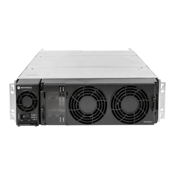
ASTRO 25 INTEGRATED VOICE AND DATA BASE RADIO
Brand:
Motorola
| Category:
Radio
| Size: 15.17 MB
Table of Contents
Table of Contents
7
GTR 8000 Base Radio Description
29
Introduction
29
GPW 8000 Receiver
30
GTR 8000 Base Radio/Gpw 8000 Receiver Components
30
Table 1-1 Base Radio/Receiver Modules and Function
30
Supported System Configurations
31
Supported Frequencies for Trunked IV&D and Conventional Architectures
31
Supported Frequencies for HPD
32
Overview for a GTR 8000 Base Radio in a Trunked IP Simulcast Subsystem
32
Overview for a GTR 8000 Base Radio in a Trunked Single-Site Repeater Configuration
32
How to Configure the HP2610 Ethernet LAN Switch
34
Overview for a GTR 8000 Base Radio in a High Performance Data (HPD) Subsystem
34
Figure 1-4 GTR 8000 Base Radios in HPD Remote Site
35
Overview for a GTR 8000 Base Radio or GPW 8000 Receiver in Conventional Architectures
36
ASTRO 25 Conventional Base Radio/Receiver
36
Analog Conventional Base Radio/Receiver
37
Power Efficiency Package
38
Table 1-2 Standby Power Consumption
39
GTR 8000 Base Radio/Gpw 8000 Receiver Specifications
40
Figure 1-1 GTR 8000 Base Radio/Gpw 8000 Receiver
40
GTR 8000 Base Radio/Gpw 8000 Receiver Specifications for Integrated Voice and Data (700 and 800 Mhz)
41
Table 1-3 GTR 8000 Base Radio/Gpw 8000 Receiver General Specifications IV&D (700 and 800 Mhz)
41
Table 1-4 GTR 8000 Base Radio Transmitter Specifications for IV&D (700 and 800 Mhz)
42
Table 1-5 GTR 8000 Base Radio/Gpw 8000 Receiver Specifications for IV&D (700 and 800 Mhz)
42
Industry Canada
44
Table 1-6 GTR 8000 Base Radio/Gpw 8000 Receiver FCC Identification for IV&D (700 and 800 Mhz)
44
Table 1-7 GTR 8000 Base Radio/Gpw 8000 Receiver Industry Canada for IVD (700 and 800 Mhz)
44
GTR 8000 Base Radio/Gpw 8000 Receiver Specifications for Integrated Voice and Data UHF R1
45
(380-435 Mhz)
45
Table 1-8 GTR 8000 Base Radio/Gpw 8000 Receiver General Specifications for IV&D UHF R1 (380-435 Mhz)
46
Table 1-9 GTR 8000 Base Radio Transmitter Specifications for IV&D UHF R1 (380-435 Mhz)
46
Industry Canada
48
Table 1-10 GTR 8000 Base Radio/Gpw 8000 Receiver Specifications for IV&D UHF R1 (380-435 Mhz)
48
Table 1-11 GTR 8000 Base Radio/Gpw 8000 Receiver FCC Identification for IV&D UHF R1 (380-435 Mhz)
48
Table 1-12 GTR 8000 Base Radio/Gpw 8000 Receiver Industry Canada for IV&D (UHF R1 380-435 Mhz)
48
GTR 8000 Base Radio/Gpw 8000 Receiver Specifications for Integrated Voice and Data UHF R2
49
(435-524 Mhz)
49
Table 1-13 GTR 8000 Base Radio/Gpw 8000 Receiver General Specifications for IV&D UHF R2 (435-524 Mhz)
49
Table 1-14 GTR 8000 Base Radio Transmitter Specifications for IV&D UHF R2 (435-524 Mhz)
50
Table 1-15 GTR 8000 Base Radio/Gpw 8000 Receiver Specifications for IV&D UHF R2 (435-524 Mhz)
52
Table 1-16 GTR 8000 Base Radio/Gpw 8000 Receiver FCC Identification for IV&D UHF R2 (435-524 Mhz)
52
Industry Canada
53
GTR 8000 Base/Gpw 8000 Receiver Radio Specifications for Integrated Voice and Data VHF (136-174 Mhz)
53
Table 1-17 GTR 8000 Base Radio/Gpw 8000 Receiver Industry Canada for IV&D (UHF R2 435-524 Mhz)
53
Table 1-18 GTR 8000 Base Radio/Gpw 8000 Receiver General Specifications for IV&D VHF (136-174 Mhz)
54
Table 1-19 GTR 8000 Base Radio Transmitter Specifications for IV&D VHF (136-174 Mhz)
54
Table 1-20 GTR 8000 Base Radio/Gpw 8000 Receiver Specifications for IV&D VHF (136-174 Mhz)
55
Table 1-21 GTR 8000 Base Radio/Gpw 8000 Receiver FCC Identification for IV&D VHF (136-174 Mhz)
56
Industry Canada
57
GTR 8000 Base Radio Specifications for High Performance Data (700 and 800 Mhz)
57
Table 1-22 GTR 8000 Base/Gpw 8000 Receiver Radio Industry Canada for IV&D (VHF 136-174 Mhz)
57
Table 1-23 General Specifications for GTR 8000 Base Radio for HPD (700 and 800 Mhz)
57
Table 1-24 Transmitter Specifications for GTR 8000 Base Radio for HPD (700 and 800 Mhz)
58
Table 1-25 Receiver Specifications for GTR 8000 Base Radio (700 and 800 Mhz HPD)
58
Industry Canada
59
Table 1-26 FCC Identification for GTR 8000 Base Radio for HPD (700 and 800 Mhz)
59
Table 1-27 Industry Canada for GTR 8000 Base Radio (700/800 Mhz)
59
GTR 8000 Base Radio Theory of Operation
61
Functions of the GTR 8000 Base Radio Modules
61
Function of the Transceiver Module
61
Figure 2-1 Transceiver Module (Front View)
61
Figure 2-2 Transceiver Control Board Information Flow
62
Transceiver Control Board
62
Transceiver RF Board
62
Exciter
63
Figure 2-3 Transceiver Reset Switch (Viewable through Drop-Down Door)
63
Receiver
63
Table 2-1 Transceiver Front Reset Switch Functions
63
Transceiver External Interfaces
63
Transceiver Switch
63
Transceiver Option Card Intercom Button
64
Transceiver Ports (Rear)
64
Function of the Power Amplifier Module
64
Figure 2-4 Transceiver Option Card Intercom Button (Behind Fan Module)
64
Figure 2-5 Transceiver Module (Backplane Connections)
64
Figure 2-6 Power Amplifier Module
65
Power Amplifier Input/Output Connections
65
Function of the Fan Module
66
Figure 2-7 Power Amplifier (Backplane Connections)
66
Function of the Power Supply
67
Figure 2-8 Fan Module
67
Figure 2-9 Power Supply
67
AC/DC Power Distribution - Base Radio
69
Figure 2-10 AC and DC Power Distribution in the GTR 8000 Base Radio
69
Power Supply Battery Charger
69
Battery Temperature Sensor Cable
70
ON/OFF Switch for Power Supply and Battery Charger
70
Table 2-2 ON/OFF Switch - States for Power Supply and Battery Charger
70
Figure 2-11 Power Supply Connections (Rear)
71
Power Supply Module - Backplane Connections
71
Table 2-3 Power Supply Module Backplane Connections
71
Backplanes and Card Cages
72
RFDS Modules
72
RFDS - Preselector (700/800 Mhz)
72
RFDS - Preselector (UHF)
72
Figure 2-12 Preselector Filter (700/800 Mhz)
72
RFDS - Preselector (VHF)
73
RFDS - Transmit Filter (700/800 Mhz)
73
Figure 2-13 Preselector (UHF)
73
Figure 2-14 Preselector (VHF)
73
RFDS - Duplexer (700/800 Mhz)
74
RFDS - Duplexer (UHF)
74
Figure 2-15 Transmit Filter (700/800 Mhz)
74
Figure 2-16 Duplexer (700/800 Mhz)
74
RFDS - Duplexer (VHF)
75
Figure 2-17 Duplexer (UHF)
75
RFDS - External Dual Circulator/Isolator Tray (700/800 Mhz)
76
Figure 2-18 Duplexer (VHF)
76
RFDS - External Dual Circulator/Isolator Tray (UHF)
77
Figure 2-19 External Dual Circulator/Isolator Tray (700/800 Mhz)
77
RFDS - External Dual Circulator/Isolator Tray (VHF)
78
Antenna Relay Module
78
Figure 2-20 External Dual Circulator/Isolator Tray (UHF)
78
Figure 2-21 Antenna Relay Module Connections
79
Mounting Locations
79
Figure 2-22 Base Radio Backplane Mounting Location
80
Figure 2-23 Antenna Relay Module Mounted on Backplane Cover
81
Figure 2-24 Antenna Relay Module Mounted on Peripheral Tray
82
Functional Operation
82
Figure 2-25 Functional Block and Interconnect Diagram for Antenna Relay Module (Bracket Mounting)
83
GTR 8000 Base Radio Installation
85
Pre-Installation Tasks
85
Equipment Installation Process Overview
85
General Safety Precautions
86
Figure 3-1 Warning Label on Hot Modules
87
DC Mains Grounding Connections
88
Connection to Primary Power
88
Disconnect Device - Permanently Connected
88
Multiple Power Source
88
Replaceable Batteries
89
Equipment Racks
89
Lifting Equipment Racks Horizontally
89
Lifting Equipment Racks Vertically
89
Figure 3-2 Lengths and Angles for Lifting Using the Eyenuts
90
Maintenance Requiring Two People
89
General Installation Standards and Guidelines
91
General Site Preparation Overview
91
Figure 3-3 Proper Alignment of the Eyenuts
91
General Equipment Inspection and Inventory Recommendations
92
Table 3-1 Activities for Site Preparation
92
General Placement and Spacing Recommendations
93
General Cabinet Bracing Recommendations
93
General Floor Mounting Procedure for Cabinets or Racks
93
General Bonding and Grounding Requirements
94
General Cabling Requirements
94
General Power Guidelines and Requirements
95
General AC Power Guidelines and Requirements
95
General Battery Installation Recommendations
96
General Breaker Recommendations
96
Table 3-2 Heavy Gauge Wire Resistance Examples
96
General Electrostatic Discharge Recommendations
97
FCC Requirements
97
Networking Tools
97
General Installation/Troubleshooting Tools
98
General Tools
98
Rack Tools
98
Technical Support for Installation
99
Site-Specific Information
100
GTR 8000 Base Radio Hardware Installation
100
Placement and Spacing
100
Rack Mounting the GTR 8000 Base Radio
101
Figure 3-4 Base Radio/Receiver Mounted in Rack
101
How to Mount the Base Radio/Receiver
102
Connecting Power
102
Connecting Power Cables to a GTR 8000 Base Radio
102
DC Power Connection Wire Gauge Calculations for HPD
103
DC Power Connection Wire Gauge Calculations for Integrated Voice and Data
103
Table 3-3 DC Power Connection Wire Gauge Maximum Distances for Integrated Voice & Data
103
Table 3-4 Power Connection Wire Gauge Maximum Distances for HPD
104
Mounting the Battery Temperature Sensor
105
Grounding the GTR 8000 Base Radio
106
How to Ground Base Radio/Receiver
107
Connections - Rear (Integrated Voice and Data)
107
Figure 3-7 Rack Grounding
107
Figure 3-8 Base Radio/Receiver Integrated Voice & Data Backplane
108
Table 3-5 Base Radio/Receiver Backplane Connections for Integrated Voice & Data
108
Connections - Rear (HPD)
110
Figure 3-9 Base Radio - HPD Backplane
110
Table 3-6 Base Radio Backplane Connections for HPD
110
Connections - Front
111
Figure 3-10 Base Radio/Receiver - Front
112
Table 3-7 Transceiver Connections - Front
112
System Connector Ports (Conventional)
114
Table 3-8 50-Pin System Connector Pin-Outs (Conventional)
114
Figure 3-11 50-Pin System Connector Pin-Outs (Conventional)
117
Figure 3-12 Wireline Port Pin-Outs
117
Table 3-9 Wireline Port Pin-Outs
117
Wireline Port Pin-Outs
117
Figure 3-13 Microphone Port Pin-Outs
118
Microphone Port Pin-Outs
118
Speaker Port Pin-Outs
118
Table 3-10 Microphone Port Pin-Outs
118
Table 3-11 Speaker Port Pin-Outs
118
Figure 3-14 Speaker Port Pin-Outs
119
GTR 8000 Base Radio - Part 68 Information
119
Port Pin-Outs
119
Table 3-12 V.24 Port Pin-Outs
119
Installation/Troubleshooting Tools
120
Quick Connect RF Coaxial Adapters for GTR 8000 Base Radio Support
120
Table 3-13 Quick Connect RF Coaxial Adapters for GTR 8000 Base Radio Support
120
Device Software Installation Prerequisites
121
Using Software Download
123
Device Installation Using the UNC
125
Discovering a Device with the UNC
126
Loading Device os Images to the UNC
128
Loading Software to a Device
129
Enabling FTP Service
130
Transferring and Installing the os Image
130
Figure 3-15 Voyencecontrol Welcome Page
131
Figure 3-16 Voyencecontrol Login Window
132
Figure 3-17 Voyencecontrol Dashboard
132
Inspecting Device Properties for Transferred and Installed Software
134
Disabling FTP Service
135
GTR 8000 Base Radio Configuration
137
Configuration Software
137
Discovering Devices in the UNC
137
Security/Authentication Services
138
Figure 4-1 Snmpv3 Security Level Option Prompt
138
Configuring a Device Using CSS
139
Initial Configuration of a Device Using CSS
139
Figure 4-2 CSS Login Banner
139
Connecting through a Serial Port Link
140
Serial Connection Configurations
142
Figure 4-3 CSS Login Banner
142
Setting the Device IP Address and Pairing Number Using CSS
143
Pairing to a Comparator
144
Serial Security Services Using CSS
145
Setting the Serial Security Services Using CSS
145
Resetting Snmpv3 User Credentials to Factory Defaults Using CSS
146
Connecting through an Ethernet Port Link
147
Figure 4-4 Snmpv3 Security Level Option Prompt
149
Ethernet Connection Configurations
150
Setting the BR/CM Pairing Number Using CSS
150
Changing Snmpv3 Configuration and User Credentials Using CSS
151
Setting the Date and Time Using CSS
151
Adding or Modifying an Snmpv3 User Using CSS
154
Performing an Snmpv3 Connection Verification Using CSS
155
Configuring DNS Using CSS
156
Table 4-1 DNS Nameservers for Devices in Dynamic System Resilience and Non-Dynamic System Resilience Sites
156
Table 4-2 Conventional Comparator System Name Variables
156
Figure 4-5 CSS Network Services Configuration - DNS Tab
157
How to Configure DNS Using CSS
157
Customizing the Login Banner Using CSS
158
Setting the SWDL Transfer Mode Using CSS
159
Figure 4-6 Remote Access Configuration Tab
160
Setting the NTP Server Settings
160
Figure 4-7 Password Configuration Window
161
Setting up the Local Password Configuration Using the CSS
161
CSS Configuration Parameters for the GTR 8000 Base Radio (Trunked Simulcast)
162
CSS Configuration Parameters for the GTR 8000 Base Radio (Trunked Repeater)
163
CSS Configuration Parameters for the GTR 8000 Base Radio (HPD)
164
CSS Configuration Parameters for the GTR 8000 Base Radio (Conventional)
166
Configuring Tx Power Values and Battery Type
167
Setting RMC System Gain
168
Using Voyencecontrol to Configure Centralized Authentication on Devices
169
GTR 8000 Base Radio Optimization
171
Aligning the Internal Frequency Reference Oscillator
171
GTR 8000 Base Radio Time and Frequency Inputs
172
Equalizing the Battery
172
Table 5-1 Base Radio Time and Frequency Inputs
172
Aligning ASTRO Simulcast (Trunked Operation)
173
Aligning Astro/Analog Simulcast (Conventional Operation)
173
Aligning Carrier Squelch
173
Aligning Tx Wireline
174
Aligning Rx Wireline
174
Tuning a Preselector
174
VHF Tuning Procedures
175
Calculating Proper VHF Alignment Frequency
175
Calculating the VHF Alignment Frequency for a Single Receive Frequency
175
Calculating the VHF Alignment Frequency for Multi Receive Frequencies
175
Preparing the Equipment for VHF Alignment
176
VHF Tuning Procedure
176
Figure 5-1 Preselector Tuning - VHF
177
Tuning the VHF Preselector
178
UHF Tuning Procedures
178
Calculating Proper UHF Alignment Frequency
178
Calculating the UHF Alignment Frequency for a Single Receive Frequency
178
Calculating the UHF Alignment Frequency for Multi Receive Frequencies
179
Preparing the Equipment for UHF Alignment
180
UHF Tuning Procedure
180
Figure 5-2 Preselect Tuning - UHF
181
Tuning the UHF Preselector
182
Tuning a Duplexer
182
Field Tuning Overview
182
Required Test Equipment
183
Tuning a 700/800 Mhz Duplexer
183
Tuning a VHF Duplexer
183
Figure 5-3 VHF Duplexer Tuning Setup
184
Setting up for Tuning a VHF Duplexer
184
Figure 5-4 Test Equipment Set up for Tuning VHF Duplexer Low Pass Resonator
185
How to Set up Tuning the VHF Duplexer
185
Tuning VHF Duplexer Low Pass Resonators
185
Figure 5-5 Test Equipment Set up for Tuning VHF Duplexer High Pass Resonator
186
How to Tune VHF Duplexer Low Pass Resonators
186
Tuning VHF Duplexer High Pass Resonators
186
Figure 5-6 Test Equipment Set up for Tuning VHF Duplexer High Notch Loop Assemblies
187
How to Tune VHF Duplexer High Pass Resonators
187
Tuning VHF Duplexer High Notch Loop Assemblies
187
Figure 5-7 Test Equipment Set up for Tuning VHF Duplexer Low Notch Loop Assemblies
188
How to Tune VHF Duplexer High Notch Loop Assemblies
188
Tuning VHF Duplexer Low Notch Loop Assemblies
188
Figure 5-8 Verifying VHF Duplexer Insertion Loss - Connecting Test Equipment
189
How to Tune VHF Duplexer Low Notch Loop Assemblies
189
Verifying VHF Duplexer Insertion Loss
189
Figure 5-9 Verifying VHF Duplexer Insertion Loss - Connecting Duplexer Cable Assembly
190
Figure 5-10 Verifying VHF Duplexer Isolation - Connecting Test Equipment
191
How to Verify VHF Duplexer Insertion Loss
191
Verifying VHF Duplexer Isolation
191
Figure 5-11 Verifying VHF Duplexer Isolation - Connecting Duplexer Cable Assembly
192
How to Verify VHF Duplexer Isolation
193
VHF Duplexer Post Tuning Checks
193
Tuning a UHF Duplexer
193
Figure 5-12 UHF Duplexer Tuning Setup
194
Setting up for Tuning a UHF Duplexer
194
Figure 5-13 Test Equipment Set up for Tuning UHF Duplexer Low Pass Resonator
195
How to Set up Tuning the UHF Duplexer
195
Tuning UHF Duplexer Low Pass Resonators
195
Figure 5-14 Test Equipment Set up for Tuning UHF Duplexer High Pass Resonator
196
How to Tune UHF Duplexer Low Pass Resonators
196
Tuning UHF Duplexer High Pass Resonators
196
Figure 5-15 Test Equipment Set up for Tuning UHF Duplexer High Notch Loop Assemblies
197
How to Tune UHF Duplexer High Pass Resonators
197
Tuning UHF Duplexer High Notch Loop Assemblies
197
Figure 5-16 Test Equipment Set up for Tuning UHF Duplexer Low Notch Loop Assemblies
198
How to Tune UHF Duplexer High Notch Loop Assemblies
198
Tuning UHF Duplexer Low Notch Loop Assemblies
198
Figure 5-17 Verifying UHF Duplexer Insertion Loss - Connecting Test Equipment
199
How to Tune UHF Duplexer Low Notch Loop Assemblies
199
Verifying UHF Duplexer Insertion Loss
199
Figure 5-18 Verify UHF Duplexer Insertion Loss - Connecting Duplexer Cable Assembly
200
Figure 5-19 Verifying UHF Duplexer Isolation - Connecting Test Equipment
201
How to Verify UHF Duplexer Insertion Loss
201
Verifying UHF Duplexer Isolation
201
Figure 5-20 Verifying UHF Duplexer Isolation - Connecting Duplexer Cable Assembly
202
How to Verify UHF Duplexer Isolation
203
UHF Duplexer Post Tuning Checks
203
Testing the GTR 8000 Base Radio/Gpw 8000 Receiver Performance with a Service Monitor for Integrated Voice and Data
203
Deviation Standards (Digital Operation)
204
Table 5-2 Deviation Standards for ASTRO 25 System Test Patterns
204
Monitoring the Power Supply Module
205
Verifying Receiver Performance (Digital Operation)
205
Figure 5-21 Metering Screen Window
205
Verifying Receiver Performance (Analog Operation)
208
Checking Receiver Sensitivity (Self-Test Method) (IV and D)
209
Monitoring the Transmitter Metering Points
210
Verifying Transmitter Performance (Digital Operation)
211
Verifying Transmitter Performance (Analog Operation)
213
Figure 5-22 Configuration for Modulation Fidelity Measurement (Aeroflex 2975 Series Service Monitor)
213
Testing the GTR 8000 Base Radio Performance with a Service Monitor for HPD
215
Setting up the HPD Service Monitor for Testing the Base Radio
216
Figure 5-24 HPD Service Monitor Test Screen (Aeroflex 3900 Series Service Monitor)
216
Performing In-Band Power Meter User Calibration
218
Measuring HPD BR Tx Power, Frequency Accuracy and Tx EVM
219
Figure 5-25 HPD Service Monitor - RF Control Settings Window (Aeroflex 3900 Series Service Monitor)
219
Figure 5-26 CSS Test and Measurement Screen
221
Figure 5-27 HPD Service Monitor - Rx Meter Subscreen, Reset Soft Keys (Aeroflex 3900 Series Service Monitor)
221
Measuring HPD BR Rx Sensitivity and Rx BER
222
Figure 5-28 HPD Service Monitor - RF Control Settings Window (Aeroflex 3900 Series Service Monitor)
223
Figure 5-29 CSS Test and Measurement Screen
225
Figure 5-30 HPD Service Monitor - Rx Meter Subscreen and Soft Keys (Aeroflex 3900 Series Service Monitor)
226
Checking Receiver Sensitivity (Self-Test Method) (HPD)
227
Figure 5-31 CSS Test and Measurement Screen
228
GTR 8000 Base Radio Maintenance
229
Fan Grill Cleaning Instructions
229
Aligning the Internal Frequency Reference Oscillator
229
GTR 8000 Base Radio Operation
231
Base Radio Operational States for Trunked Simulcast
231
Base Radio Operational States for Trunked Repeater and HPD
231
Base Radio Operational States for Conventional
232
Packet Data Interactions with Multiple Nac's
232
Supplementary Signaling Interactions with Multiple Nac's
232
Illegal Carrier Determination Feature (Trunked)
233
RF Channel Interference Determination Feature (Conventional)
233
GTR 8000 Base Radio Troubleshooting
235
General Troubleshooting
235
Table 8-1 GTR 8000 Base Radio General Troubleshooting
235
Troubleshooting Tools
238
Using Unified Event Manager to Monitor Links and Components
238
Analyzing Unified Event Manager Active Alarm Window
238
Diagnostic Options in UEM
239
MOSCAD Network Fault Management
239
Figure 8-1 MOSCAD Network Fault Management
239
Table 8-2 Base Radio Diagnostic Options in UEM
239
Using Unified Network Configurator for Troubleshooting
240
Using Configuration/Service Software (CSS) for GTR 8000 Base Radio Troubleshooting
240
Alarm Log from Internal Diagnostic Tests
240
Resetting Passwords and Snmpv3 Passphrases
240
Site Controller Failure - Impact on GTR 8000 Base Radio for Trunked Operation
241
Conventional Site Controller Failure - Impact on GTR 8000 for Conventional Operation
241
Table 8-3 Local Password and Snmpv3 Passphrase Troubleshooting
241
Using Motorola System Support Center (SSC)
242
Gathering Information before Calling Motorola
242
Where to Call for Service
242
Motorola System Support Center (SSC)
242
Use of Subcontractors
243
GTR 8000 Base Radio FRU Procedures
245
Field Replaceable Units (Frus) and Parts
245
Table 9-1 GTR 8000 Base Radio Field Replaceable Units
245
Table 9-2 GTR 8000 Base Radio Field Replaceable Parts
247
Replacing a Radio Transceiver Module
248
Table 9-3 Individual Replaceable Parts on External Dual Circulator Tray
248
Table 9-4 GTR 8000 Base Radio Cables
248
Figure 9-1 Transceiver Module
249
Figure 9-2 GTR 8000 Base Radio Modules
249
How to Replace a Transceiver Module
249
Replacing the Fan Assembly
254
Figure 9-3 Fan Assembly
255
How to Replace the Fan Assembly
255
Replacing a Power Supply
257
Figure 9-4 Power Supply
257
How to Replace a Power Supply
257
Replacing a Power Supply Fan
259
Figure 9-5 Power Supply Fan
259
How to Replace a Power Supply Fan
260
Replacing a Power Amplifier
261
Figure 9-6 Power Amplifier Module
262
Figure 9-7 Captive Screws
262
How to Replace a Power Amplifier
262
Figure 9-8 GTR 8000 Power Amplifier RF Cable (Front)
264
Replacing the GTR 8000 Base Radio Backplane
265
Figure 9-9 GTR 8000 Base Radio Showing Connections to Backplane through Backplane Cover
265
How to Replace a GTR 8000 Base Radio Backplane
265
Figure 9-10 Fan Cable Connector
268
Figure 9-11 EMI Spring Panel Guide Rail Alignment
269
Figure 9-12 Preselector Filter (700/800 Mhz)
271
Figure 9-13 Preselector Filter (UHF)
271
Figure 9-14 Preselector Filter (VHF)
271
How to Replace a Preselector Filter
272
Replacing a Preselector Filter
271
Replacing Transmit Filters (700/800 Mhz)
272
Figure 9-15 Transmit Filter (700/800 Mhz)
273
How to Replace Transmit Filters (700/800 Mhz)
273
Replacing the Dual Circulator/Isolator Modules
274
Figure 9-16 External Dual Circulator/Isolator Tray (700/800 Mhz)
275
Figure 9-17 External Dual Circulator/Isolator Tray (UHF)
276
How to Replace the Dual Circulator/Isolator Modules
277
Replacing a Duplexer (700/800 Mhz)
279
Figure 9-18 Duplexer Module (700/800 Mhz)
279
How to Replace a Duplexer (700/800 Mhz)
280
Replacing a Duplexer (UHF)
281
Figure 9-19 Duplexer Module (UHF)
281
How to Replace a Duplexer (UHF)
281
Replacing a Duplexer (VHF)
283
Figure 9-20 Duplexer Module for IVD (VHF)
283
How to Replace a Duplexer (VHF)
284
Replacing an Antenna Relay
284
How to Replace an Antenna Relay
285
GTR 8000 Base Radio Reference
287
Leds
287
Figure 10-1 Transceiver Leds (Viewable through Drop-Down Door)
287
GTR 8000 Base Radio Transceiver Leds
287
Transceiver Status and Alarm Leds
287
Table 10-1 Transceiver Status and Alarm Leds
288
Table 10-2 Transceiver Ethernet Link Status Leds
288
Transceiver Application-Controlled Leds
288
Transceiver Ethernet Link Status Leds
288
Table 10-3 Transceiver Application-Controlled Leds
289
Table 10-4 Transceiver Services-Controlled Leds
289
Transceiver Services-Controlled Leds
289
Figure 10-2 Transceiver Option Card Intercom LED (Viewable Behind the Fan Module)
290
Figure 10-3 Power Amplifier Leds, Viewable through Drop-Down Door
290
Power Amplifier Leds
290
Transceiver Option Card Intercom LED
290
Fan Module LED
291
Figure 10-4 Fan Module-Alarm LED (Lower Right Corner)
291
Table 10-5 Power Amplifier Leds
291
Figure 10-5 Power Supply Module
292
Power Supply Leds
292
Table 10-6 Power Supply Leds
292
RFDS Equipment Specifications
293
Table 10-7 Transmit Filter Specifications (700/800 Mhz)
293
Transmit Filter Specifications (700/800 Mhz)
293
Preselector Filter Specifications (700/800 Mhz)
294
Preselector Filter Specifications (UHF)
294
Table 10-8 Preselector Filter Specifications (700/800 Mhz)
294
Table 10-9 Preselector Filter Specifications (UHF)
294
Duplexer Specifications (700/800 Mhz)
295
Preselector Filter Specifications (VHF)
295
Table 10-10 Preselector Filter Specifications (VHF)
295
Table 10-11 Duplexer Specifications (700/800 Mhz)
295
Duplexer Specifications (UHF)
296
Duplexer Specifications (VHF)
296
Table 10-12 Duplexer Specifications (UHF)
296
Table 10-13 Duplexer Specifications (VHF)
296
External Dual Circulator Specifications (700/800 Mhz)
297
External Dual Circulator Specifications (UHF)
297
Table 10-14 External Dual Circulator Specifications (700/800 Mhz)
297
Table 10-15 External Dual Circulator Specifications (UHF)
297
Antenna Relay Specifications
298
External Dual Circulator Specifications (VHF)
298
Table 10-17 Antenna Relay Specifications
298
GTR 8000 Base Radio Disaster Recovery
301
Recovery Sequence for GTR 8000 Base Radio
301
Performing a Site Download with PSC 9600 Site Controllers
303
Performing a Site Download with GCP 8000 Site Controllers
305
Appendix A Conventional GTR 8000 Base Radio Option Kits
307
T2-2R, T3-3R, and T4-4R Receiver Mute Option Kits
307
Figure A-1 T2-2R Receiver Mute Option Kit Wiring Diagram
308
T2-2R Receiver Mute Option Kit
308
T2-2R Receiver Mute Option Kit Parts List
309
Table A-1 T2-2R Receiver Mute Option Kit Parts List
309
Figure A-2 T3-3R Receiver Mute Option Kit Wiring Diagram
310
T3-3R Receiver Mute Option Kit
310
T3-3R Receiver Mute Option Kit Parts List
311
Table A-2 T3-3R Receiver Mute Option Kit Parts List
311
Figure A-3 T4-4R Receiver Mute Configuration
312
Figure A-4 T4-4R Splitter and Antenna Relay Tray
312
T4-4R Receiver Mute Option Kit
312
Figure A-5 T4-4R Receiver Mute Option Kit Wiring Diagram
313
T4-4R Receiver Mute Option Kit Parts List
314
Table A-3 T4-4R Receiver Mute Option Kit Parts List
314
Expected Site Performance for T2-2R, T3-3R, and T4-4R Receiver Mute
315
Table A-4 Total Transmit and Receive Attenuation for T2-2R, T3-3R, and T4-4R Receiver Mute
315
Figure A-6 Tn-Nr Receiver Mute Option Kit Wiring Diagram
316
Tn-Nr Receiver Mute Option Kit
316
Installing the T2-2R, T3-3R, and T4-4R Receiver Mute Option Kits
317
Table A-5 Tn-Nr Receiver Mute Option Kit Parts List
317
Tn-Nr Receiver Mute Option Kit Parts List
317
Configuring the T2-2R, T3-3R, and T4-4R Receiver Mute Option Kits
319
T1-2R with Talk-Around Option Kit
322
Figure A-8 T1-2R Talk-Around Option Kit Wiring Diagram
323
T1-2R with Talk-Around Option Kit Parts List
324
Table A-6 T1-2R with Talk-Around Option Kit Parts List
324
Expected Site Performance for T1-2R with Talk-Around
325
Installing the T1-2R with Talk-Around Option Kit
325
Table A-7 Total Transmit and Receive Attenuation for T1-2R with Talk-Around
325
Configuring the T1-2R with Talk-Around Option Kit
326
T2-2R with Duplexer and Triple Relay Option Kit
329
Figure A-9 T2-2R with Duplexer and Triple Relay Configuration
329
Figure A-10 Triple Antenna Relay Tray
330
Figure A-11 T2-2R with Duplexer and Triple Relay Option Kit Wiring Diagram
331
T2-2R with Duplexer and Triple Relay Option Kit Parts List
332
Table A-8 T2-2R with Duplexer and Triple Relay Option Kit Parts List
332
Expected Site Performance for T2-2R with Duplexer and Triple Relay
333
Installing the T2-2R with Duplexer and Triple Relay Option Kit
333
Table A-9 Total Transmit and Receive Attenuation for T2-2R with Duplexer and Triple Relay
333
Configuring the T2-2R with Duplexer and Triple Relay Option Kit
334
Appendix B Analog Simulcast Cable Assembly
339
Analog Simulcast Cable Kit Parts List
339
Table B-1 Analog Simulcast Cable Kit Parts List
339
Assembling the Analog Simulcast Cable and Panel
340
Figure B-1 Analog Simulcast Cable and Panel Assembly
340
Installing the Analog Simulcast Cable in an Open Rack Configuration
341
Figure B-2 Analog Simulcast Cable in an Open Rack Configuration
341
Figure B-3 Analog Simulcast Assembly in Rack - GTR 8000 Base Radio Backplane
342
Figure B-4 Connected Analog Simulcast Cable - GTR 8000 Base Radio Front View
342
Installing the Analog Simulcast Cable in a Cabinet Configuration
343
Figure B-5 Analog Simulcast Cable - GTR 8000 Base Radio with Fan Modules
343
Figure B-6 Analog Simulcast Cable in a Cabinet Configuration
343
Analog Simulcast Cable Pin Assignment
344
Figure B-7 Telco T57 Female Connector on the Analog Simulcast Cable
345
Table B-2 Analog Simulcast Cable Pin Assignment
345
Advertisement
Advertisement
Related Products
Motorola ASTRO 25 GTR 8000
Motorola GTX/LCS 2000
Motorola GM950
Motorola GP340 ATEX
Motorola GM340
Motorola GP240
Motorola GP140 Series
Motorola GM398
Motorola GM1200 Series
Motorola GP series
Motorola Categories
Cell Phone
Two-Way Radio
Baby Monitor
Cordless Telephone
Radio
More Motorola Manuals
Login
Sign In
OR
Sign in with Facebook
Sign in with Google
Upload manual
Upload from disk
Upload from URL