Sign In
Upload
Manuals
Brands
Honeywell Manuals
Security System
NetAXS NX4S1
Honeywell NetAXS NX4S1 Manuals
Manuals and User Guides for Honeywell NetAXS NX4S1. We have
1
Honeywell NetAXS NX4S1 manual available for free PDF download: Installation Manual
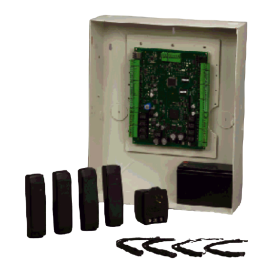
Honeywell NetAXS NX4S1 Installation Manual (73 pages)
Access Control Unit
Brand:
Honeywell
| Category:
Security System
| Size: 2.61 MB
Table of Contents
Installation Guide
1
Table of Contents
3
Ist of
9
Netaxs™ NX4S1 Installation
11
Warnings and Cautions
11
Limited Warranty
12
Product Liability, Mutual Indemnification
12
Federal Communications Commission
13
Industry Canada
13
Underwriters Laboratories Incorporated
14
1 Notices
11
2 Introduction
15
Access Control Overview
15
Netaxs™ Access Overview
15
3 Panel Components and Descriptions
16
Figure 1: NX4S1 Panel Components
16
Netaxs™ Access Control Unit
17
Real-Time Clock Protection
17
Memory Protection
17
Reader and AUX Power
17
Battery
18
Enclosure
18
Power Supply
18
Suppressors
18
4 Installation
19
Cabinet Mounting
20
Figure 2: Netaxs™ NX4S1 Panel Cabinet, Front View
20
Figure 3: Netaxs™ NX4S1 Panel Cabinet, Top View
21
Figure 4: Netaxs™ NX4S1 Panel Cabinet, Bottom View
21
Figure 5: Netaxs™ Panel Cabinet, Left View
22
Figure 6: Netaxs™ Nx4S1Panel Cabinet, Right View
23
Reader Wiring
24
Supervised Input Wiring
24
Table 1 Reader Wiring
24
Table 2 Default Supervised Input Assignments
24
Figure 7: Typical Supervised Input Wiring Diagram
25
NX4S1 Control Output Wiring
26
Communications
26
RS-232 Communications
26
Figure 8: RJ-45 Serial Port
27
Figure 9: RS-232 Configuration
27
RS-485 Communications
28
Figure 10: RS-485 Configuration Via N-485-PCI-2 or PCI-3
28
Ethernet TCP/IP Communications
29
Figure 11: RS-485 Configuration Via Netaxs™ Gateway
29
Figure 12: Ethernet TCP/IP Configuration
29
Figure 13: Ethernet MAC Address Location
30
DIP Switch Settings
31
Figure 14: DIP Switch and Jumper Locations
31
Table 3 DIP Switch Settings
32
Jumper Settings
33
Downstream I/O
33
Table 4 MIRO 32/0 DIP Switch and Jumper Settings
33
Figure 15: Default Downstream I/O Configuration with Wiring
35
Netaxs Access Control Unit NX4S1 Installation Guide, Document 800-00008, Revision a III
35
5 System Configuration
36
RS-485 Connection Via PCI-2
36
Figure 16: RS-485 Connection Via PCI-2
36
RS-485 Connection Via Netaxs
37
Figure 17: RS-485 Connection Via Netaxs
37
RS-485 Connections with Multidrop Panels at both Ends of the Cable
38
Figure 18: RS-485 Connection Via Netaxs™ with Multidrop Panels at both Ends
38
Figure 19: RS-485 Connection Via PCI-2 with Multidrop Panels at both Ends
39
RS-232 Connection
40
Figure 20: RS-232 Connection
40
Ethernet Connection
41
Figure 21: Ethernet Connection
41
LANSRLU1 Connection
42
Figure 22: LANSRLU1 Connection
42
RS-485 Short Haul Modem Connection Via PCI-2
43
Figure 23: RS-485 Short Haul Modem Connection Via PCI-2
43
RS-485 Short Haul Modem Connection Via Netaxs
44
Figure 24: RS-485 Short Haul Modem Connection Via Netaxs
44
RS-232 Short Haul Modem Connection
45
Figure 25: RS-232 Short Haul Modem Connection
45
M-56K Dial-Up Modem, RS-485 Connection Via Hub
46
Figure 26: M-56K Dial-Up Modem, RS-485 Connection Via Hub
46
M-56K Dial-Up Modem, RS-485 Connection Via Netaxs
47
Figure 27: M-56K Dial-Up Modem, RS-485 Connection Via Netaxs
47
Fiber Converter to RS-485 Connection Via PCI-2
48
Figure 28: Fiber Converter to RS-485 Connection Via PCI-2
48
Fiber Converter to RS-485 Connection Via Netaxs
49
Figure 29: Fiber Converter to RS-485 Connection Via Netaxs
49
N-485-PCI-2/Netaxs™ Access Controller Panel Connection Detail
50
Figure 30: N-485-PCI-2/Netaxs™ Access Controller Panel Connection Detail
50
Netaxs™/Netaxs™ Access Controller Panel Connection Detail
51
Figure 31: Netaxs™/Netaxs™ Access Controller Panel Connection Detail
51
6 Netaxs™ Startup
52
LED Operation
52
Figure 32: System, Relay and Power Leds
52
Table 5 LED Status
53
7 Hardware Specifications
54
Relay Contacts
54
Reader Interface
54
NX4S1 Wire Requirements
54
Maximum Output Loading
54
Common Connections
55
Mechanical
55
Environment
55
Communications and Wiring
56
Reader Wiring
56
Table 6 Communications and Wiring
56
Table 7 Reader Wiring
56
NX4S1 Wiring Diagram
57
Figure 33: NX4S1 Panel Wiring Diagram
57
8 Maintenance
58
Table 8 Troubleshooting Problems and Solutions
58
9 Troubleshooting
58
10 Technical Support
59
Normal Support Hours
59
Web
59
Basic Standalone Operations
61
Card Read / Door Lock Operation
61
Door Egress / Door Lock / Door Status Operation
61
Netaxs™ Standalone Operation
61
Standalone Settings
62
Netaxs™ Panel Hardware Settings
62
Communication Settings
62
Emulation Settings
62
Verifying Communications
62
Standalone Commands
63
T (Time) Command
63
D (Date) Command
64
L (Time Zone) Command
65
C (Card Add) Command
66
C (Card Delete) Command
66
W (Input) Command
67
P (Interlock) Command
67
Flow Control Disable/Enable
68
Netaxs™ Panel Defaults
69
Reader Ports
69
Reader LED Outputs
69
Reader Tamper Inputs
70
Door Egress Inputs
70
Door Status Inputs
71
ACFAIL and Panel Tamper Inputs
71
Additional Generic Outputs
72
Advertisement
Advertisement
Related Products
Honeywell NETAXS NX4L1
Honeywell Notifier NFS2-640/E
Honeywell Notifier HS-NCM
Honeywell Notifier DVC
Honeywell Notifier ONYXWorks-WS
Honeywell NXL Series
Honeywell NXS 0022
Honeywell NXS0005V35A5H1
Honeywell NXS0045V35A5H1
Honeywell NX 0300 5
Honeywell Categories
Thermostat
Controller
Control Unit
Security Camera
Accessories
More Honeywell Manuals
Login
Sign In
OR
Sign in with Facebook
Sign in with Google
Upload manual
Upload from disk
Upload from URL