Sign In
Upload
Manuals
Brands
GE Manuals
Measuring Instruments
Phasor 16/16
GE Phasor 16/16 Manuals
Manuals and User Guides for GE Phasor 16/16. We have
1
GE Phasor 16/16 manual available for free PDF download: Operating Manual
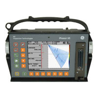
GE Phasor 16/16 Operating Manual (116 pages)
Brand:
GE
| Category:
Measuring Instruments
| Size: 6.7 MB
Table of Contents
Table of Contents
3
1 Phased Array Operation-Keypad, Menus, and Displays
9
Supplying Power
9
Powering on and off the Instrument
10
Keypad and Knob Features
10
Home Menu and Functions
11
Display Screen Features (Phased Array)
14
Startup Mode
15
Software Updates
15
2 Setting up for Phased Array Measurement
17
Language, Units of Measurement, Date, and Time
17
Display Appearance
18
Installing a Phased Array Probe
19
Connecting a Probe
19
Configuring the Instrument for a Phased Array Probe
20
Inputting Wedge-Related Information
21
Inputting Test-Piece Properties
22
Defining the Scan Parameters
25
Defining the Ultrasonic Characteristics of the Displayed Scan
27
LEG Setting to Control the Scan Range
27
Setting the Display Delay
27
Defining the Display's Starting Point
27
Pulser and Receiver Settings for Phased Array Operation
28
Setting the Pulser Voltage Level (UT-PULSER-VOLTAGE)
28
Selecting the Pulser Width (UT-PULSER-WIDTH)
29
Specifying the Receiver Frequency (UT-RECEIVER-FREQUENCY)
29
Selecting a Rectification Mode (UT-RECEIVER-ASCAN RECTIFY)
29
Managing Gates for Phased Array Operation
30
Positioning Gates
30
Selecting the TOF-Detection Method
32
Setting Gate Logic
32
Configure the Gate to Ignore or Accept Off-Screen Triggers (DISPLAY-RESULTS2-GATE SHAPE)
32
Assign TTL Output / Alarm Indication Light to a Gate (DISPLAY-RESULTS2-TTL #1)
32
Calibrating the Instrument / Probe Combination
33
Performing a Quick Calibration
33
3 Operating in Phased Array Mode
35
Selecting the Displayed View (Phased Array)
35
Displaying Results (Phased Array)
36
Controlling A-Scan Orientation and Beam Cursor Position
38
Operating in Freeze Mode (Phased Array)
40
Setting the Gain (Phased Array)
40
Operating in TCG Mode (Phased Array)
43
Recording the TCG Reference Points
44
Selecting Beam-Groups of Interest During the TCG Recording Process
46
Applying Incremental Gain to Beam Groups During the Recording Process
46
Manually Imputing TCG Points
46
Editing TCG Points
47
4 Conventional Operation: Menu System, Keypad, and Displays
49
Supplying Power
49
Powering on and off the Instrument
50
Keypad and Knob Features
50
Home Menu, Eval Menus, and Functions
50
Display Screen Features (Conventional)
55
Initial Instrument Setup
55
Language, Units of Measurement, Date, and Time
56
Display Appearance
58
Installing a Conventional Probe
58
Connecting a Conventional Probe
58
Configuring the Instrument to Match the Probe Type
58
Adjusting the Pulser Repetition Frequency (PRF)
59
Selecting a Rectification Mode
60
Setting the Pulser Voltage or Energy Level
61
Setting the A-Scan REJECT Level
61
Adjusting the A-Scan (Conventional)
61
Setting the A-Scan Range
61
Setting the Display Delay
62
Calibrating the Instrument
62
Pre-Calibration Check List
62
Using AUTOCAL to Calibrate the Instrument
62
Using the Calibration Reminder Alarm
63
Activating Instrument Upgrades
64
5 Making Conventional Measurements
65
Configuring the a and B-Gates
65
Positioning Gates
66
Selecting the TOF-Detection Method
67
Setting Gate Alarms and Outputs
67
Using Angle Beam Probes and the TRIG Menu
68
Setting Angle Beam Probe Characteristics
69
Indicating Leg with Color
69
Displaying Measured Results
69
Saving the Instrument Configuration in a Data Set
71
Locking the Gain Rotary Knob
71
Setting the Gain
71
Changing the Gain-Adjustment Increment (Db STEP)
71
Setting the User-Defined Gain Step (SETUP-GAIN-USER GAIN STEP)
71
Freezing the A-Scan Display
72
Dac/Tcg Evaluation Mode
72
Using DAC
73
Recording the DAC Curve
73
Working with DAC
73
Using TCG
74
Generating the TCG Reference Curve
74
Working with TCG
75
Adjusting DAC or TCG Display and Adding Offsets
75
Editing and Deleting DAC and TCG Reference Points
76
Deleting a DAC Curve or TCG Reference Points
76
DGS Evaluation Mode
76
Specifying a Probe and Preparing to Record the Reference Echo
77
Record the Reference Echo that Defines the DGS Curve
78
Display and Adjust the DGS Curve
79
Evaluating Results in DGS Mode
80
Locks, Error Messages
80
Validity of the DGS Method
80
Db REF Evaluation Mode
80
AWS D1.1 Weld Rating Evaluation Mode
81
JISDAC Evaluation Mode
83
Recording the JISDAC Curve
84
Working with DAC
84
Deleting a JISDAC Curve
85
6 Storing Data Sets and Generating Reports
87
Data Set Files
87
Creating Data Set Files
88
Editing Active Files
88
Recalling Existing Data Sets
89
Deleting (CLEARING) Existing Data Sets
89
Creating a Memo
89
Creating a Report Header
89
Generating a Report
90
Outputting Via the RS-232 Serial Port or Seven-Pin LEMO Connector
91
7 Technical Specifications
93
Physical Specifications
93
Phased Array / Conventional Channel Specifications
94
Environmental Tests
95
Phased Array Probes
95
8 Working in TOP View (Optional Feature)
97
Preparing for TOP View Operation
97
Setting up the Phased Array Prior to Displaying a TOP View
97
Setting up TOP View for TIMED Operation
98
Setting up TOP View for ENCODED Operation
99
Creating a TOP View
101
Freezing the Display and Navigating Data in TOP View
106
Storing the TOP View Data
108
Using TOP View's ENCODED Mode - User Application Summary
108
9 Error Messages
109
10 Index
111
Advertisement
Advertisement
Related Products
GE GeneQuant 1300
GE Phasor XS
GE Phasor CV
GE Phasor XS 16/64
GE 16174120
GE 169209
GE 169140
GE 169205
GE 169024
GE 164D3333P200-3
GE Categories
Refrigerator
Ranges
Microwave Oven
Air Conditioner
Dishwasher
More GE Manuals
Login
Sign In
OR
Sign in with Facebook
Sign in with Google
Upload manual
Upload from disk
Upload from URL