Sign In
Upload
Manuals
Brands
Canon Manuals
All in One Printer
Staple Finisher-S1
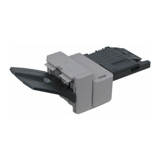
Canon Staple Finisher-S1 Manuals
Manuals and User Guides for Canon Staple Finisher-S1. We have
3
Canon Staple Finisher-S1 manuals available for free PDF download: Service Manual
Canon Staple Finisher-S1 Service Manual (233 pages)
Brand:
Canon
| Category:
All in One Printer
| Size: 6.76 MB
Table of Contents
Table of Contents
5
Chapter 1 Specifications
11
Chapter 1 Specifications
12
Product Specifications
13
Specifications
13
Names of Parts
18
External View
18
Cross-Sectional View
19
Chapter 2 Functions
20
Chapter 2 Functions
21
Basic Construction
22
Overview
22
Outline of Electric Circuits
23
Basic Operation
24
Feed Drive System
29
Overview
29
Feed Roller Control
30
Offset Roller Control
31
Feed Motor Control
35
Offset Motor Control
36
Staple Operation
37
Functional Configuration
37
Staple Motor Control
39
Stack Tray Operation
40
Overview
40
Stack Ejection
41
Stack Slide Motor Control
43
Stack Tray Shift Motor Control
44
Detecting Jams
45
Overview
45
Power Supply
47
Overview
47
Protection Function
47
Chapter 3
49
Left Cover
55
Removing the Left Cover
55
Upper Cover
55
Removing the Upper Cover
55
PCB Cover
56
Bottom Cover
57
Removing the Bottom Cover
57
Top Harness Cover
57
Removing the Top Harness Cover
57
Tray Guide Top Cover
58
Drive System
60
Drive Unit
62
Removing the PCB Cover
63
Feed Motor
63
Stack Tray Shift Motor
63
Removing the Top Harness Cover
64
Removing the Upper Cover
64
Removing the Bottom Cover
65
Removing the Left Cover
65
Removing the Stapler Cover
68
Offset Motor
71
Removing the PCB Cover
71
Removing the Top Harness Cover
72
Removing the Upper Cover
72
Removing the Offset Motor
73
Stack Slide Motor
73
Document Feeding System
78
Stack Tray Assembly
78
Process Tray Assembly
81
Feed Rollor
85
Removing the PCB Cover
85
Removing the Top Harness Cover
88
Electrical System
88
Stack Tray Paper Surface Sensor
88
Removing the Stack Tray Lower Limit Sensor
92
Process Tray Paper Sensor
92
Removing the PCB Cover
96
Removing the Process Tray Paper Sensor
96
Finisher Controller PCB
96
Front Cover Safety Switch
98
Removing the PCB Cover
98
Inlet Sensor
98
Removing the Top Harness Cover
99
Removing the Upper Cover
99
Removing the Inlet Sensor
100
Stack Slide HP Sensor
101
Stack Slide HP Sensor
104
Chapter 4 Maintenance
118
Maintenance and Inspection
119
Periodically Replaced Parts
119
Durables
119
Periodical Servicing
120
Adjustment
121
Adjustment at Time of Parts Replacement
121
Outline of Electrical Components
122
Variable Resistors (VR), Light-Emitting Diodes
125
Light-Emitting Diodes and Check Pins by PCB
125
Finisher Controller PCB
126
Offset HP Sensor
127
DIP Switch Functions
128
Table of Contents
143
Chapter 1 Specifications
145
Product Specifications
147
Specifications
147
Names of Parts
150
External View
150
Cross Section
151
Basic Construction
154
Functional Construction
154
Feed Drive System
155
Overview
155
Constraction of the Control System
156
Punch Operation
157
Power Supply
162
Power Supply Route
162
Protection Function
162
Chapter 3 Parts Replacement Procedure
163
External Covers
165
Front Cover
165
Removing the
165
Upper Cover
166
Electrical System
171
Photosensor PCB
171
Punch Controller PCB
172
Chapter 4 Maintenance
175
User Maintenance
177
User Maintenance Items
177
Adjustment
178
Adjustment at Time of Parts Replacement
178
Registering the Number of Punch Holes
178
Sensors
179
Motors and Solenoids
180
Pcbs
181
Variable Resistors (VR), Light-Emitting Diodes (LED), and Check Pins by PCB
182
Outline
182
Functions of the DIP Switch
183
Punch Controller PCB
183
Chapter 5 Error Code
186
Overview
188
Outline
188
Service Error Code
189
E590
189
Jam Codes
190
Detecting a Jam
190
Alam Code
191
Punch Waste Case Full
191
Punch Waste Case Overflow
192
Table of Contents
200
Chapter 1 Specifications
202
Specifications
204
Chapter 2 Functions
206
Chapter 3 Parts Replacement Procedure
209
Removing from the Host Machine
211
Shift Tray
211
Turning off the Host Machine
211
Mounting the Optional Tray
216
Electrical System
218
Stack Tray Paper Surface Sensor
218
Removing the Option Tray (Lower) Cover
218
Removing the Paper Sensor
218
Static Charge Eliminator 1
218
Removing the Main Tray Cover
219
Removing the Side Plate L Cover
219
Optional Tray Driver PCB
220
Removing the Option Tray (Lower) Cover
220
Removing the Option Tray Drive PCB
220
Chapter 4 Maintenance
222
Maintenance and Inspection
224
Periodically Replaced Parts
224
Durables
224
Periodical Servicing
225
Outline of Electrical Components
226
Variable Resistors (VR), Light-Emitting Diodes (LED), and Check Pins by PCB
227
Functions of the DIP Switch
227
Advertisement
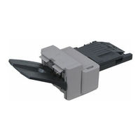
Canon Staple Finisher-S1 Service Manual (115 pages)
Brand:
Canon
| Category:
All in One Printer
| Size: 7.97 MB
Table of Contents
Table of Contents
4
Safety Precautions
6
Notes before Servicing
7
Points to Note at Cleaning
7
Product Outline
8
1 Product Outline Features
9
Specifications
10
Staple Unit
10
Names of Parts
11
External View
11
Cross Section
11
2 Technology
12
Basic Configuration
12
Functional Configuration
13
Overview of Electrical Circuitry
13
Controls
14
Basic Operation
15
Outline
15
Feed Unit
17
Outline
17
Buffer Path Cover Open/Close Detection
17
Feeding Paper to Processing Tray Unit
18
Processing Tray Unit
19
Outline
19
Stacking Operation
20
Tray Auxiliary Guide Operation
22
Alignment / Shifting Operation
23
Staple Operation
28
Stack Delivery Operation
29
Stack Tray Paper Retainer Operation
29
Stack Tray Unit
30
Stack Tray Shift Operation
30
Stack Tray Paper Height Detection Control
30
Stack Tray Paper Full Detection Control
31
Controller Unit
32
Outline
32
Detecting Jams
33
Outline
33
Power Supply
34
Outline
34
Protective Functions
34
Work of Service
35
When Replacing the Parts
35
Periodical Servicing
35
Upgrading
35
3 Periodic Servicing List of Work for Scheduled Servicing
37
4 Parts Replacement and Cleaning Procedure
38
List of Parts
38
External / Internal Cover
39
List of Main Unit
40
Motor
40
Sensor/Switch
41
Pcb
42
List of Connectors
43
Removing the Equipment
46
Layout Drawing
46
Removing the Finisher Unit from the Connected Equipment
46
Removing the Buffer Path Unit from the Connected Equipment
48
Removing the Reinforcing Plate Cover from the Connected Equipment
49
External Cover/Internal System
50
Layout Drawing
50
Removing the Front Door
51
Removing the Front Cover
52
Removing the Rear Cover
53
Removing the Upper Cover
54
Removing the PCB Cover
56
Removing the Grate-Shaped Guide
57
Major Units
59
Layout Drawing
59
Removing the Staple Cartridge
59
Removing the Staple Unit
60
Removing the Main Paddle
62
Removing the Front/Rear Alignment Plates
63
Removing the Finisher Lower Feed Guide Unit
64
Removing the Sub Paddle
69
Removing the Process Tray Upper Unit (Front/Rear)
71
How to Assemble the Process Tray Upper Unit (Front/Rear) and the Finisher Lower Feed Guide Unit
72
Removing the Process Tray Lower Unit
77
Separating the Buffer Upper Feed Guide Unit from the Buffer Lower Feed Guide Unit
78
Motors
79
Layout Drawing
79
Removing the Feed Motor (M1)
80
Remove the Paddle Motor (M3)
81
Removing the Delivery Motor (M2)
82
Removing the Front Alignment Motor (M4)
83
Removing the Rear Alignment Motor (M5)
84
Removing the Tray Auxiliary Guide Motor (M6)
85
Removing the Stack Tray Shift Motor (M8)
86
Switches
89
Layout Drawing
89
Removing the Front Door Switch (S15)
90
Removing the Stack Tray Lower Limit Sensor (S10)
91
Pcbs
92
Layout Drawing
92
Removing the Finisher Controller PCB
92
5 Adjustment
94
Adjustment Item
94
Overview
95
Dip Switch Function
96
Sensor Detection Check Mode
96
Motor Operation Check Mode
98
6 Installation
99
How to Check this Installation Procedure
99
Symbols in the Illustration
100
Check Items When Turning off the Main Power
100
Points to Note When Relocating the Host Machine
100
Product Name
100
Points to Note at Installation
101
Unpacking
101
Installation Outline Drawing
102
Checking the Contents
103
Installation Procedure
103
Without Cassette Feeding Unit
103
With Cassette Feeding Unit
108
Appendix
113
Service Tools
113
Special Tools
114
Solvents and Oils
114
General Circuit Diagram
115
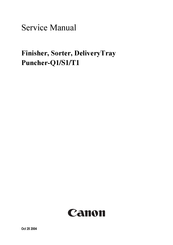
Canon Staple Finisher-S1 Service Manual (64 pages)
Brand:
Canon
| Category:
Printer Accessories
| Size: 0.93 MB
Table of Contents
Table of Contents
7
Chapter 1 Specifications
9
Product Specifications/Names of Parts
11
1Specifications
13
Product Specifications
13
Specifications
13
1External View
16
External View
16
Names of Parts
16
2Cross Section
17
Cross Section
17
Chapter 2 Functions
19
Table of Contents
21
1Functional Construction
23
Basic Construction
23
Functional Construction
23
1Overview
24
2Constraction of the Control System
24
Constraction of the Control System
24
Feed Drive System
24
Overview
24
3Punch Operation
25
Punch Operation
25
1Power Supply Route
29
2Protection Function
29
Power Supply
29
Power Supply Route
29
Protection Function
29
Chapter 3 Parts Replacement Procedure
31
Table of Contents
33
External Covers
35
Front Cover
35
Removing the
35
Upper Cover
35
Upper Cover
36
Drive System
37
Punch Motor
37
Removing the Punch Motor
37
Removing the Upper Cover
37
Electrical System
39
Photosensor PCB
39
Removing the Photosensor PCB
39
Removing the Upper Cover
39
Removing the Scrap Full Detector PCB
40
Scrap Full Detector PCB
40
Punch Controller PCB
41
Removing the Punch Controller PCB
41
Removing the Upper Cover
41
Chapter 4 Maintenance
43
Table of Contents
45
1User Maintenance Items
47
User Maintenance
47
User Maintenance Items
47
Durables
48
Maintenance and Inspection
48
Periodical Servicing
48
Periodically Replaced Parts
48
Adjustment
49
Adjustment at Time of Parts Replacement
49
Registering the Number of Punch Holes
49
1Sensors
50
2Motors and Solenoids
50
Motors and Solenoids
50
Outline of Electrical Components
50
Sensors
50
3Pcbs
51
Pcbs
51
1Outline
52
2Punch Controller PCB
52
3Functions of the DIP Switch
52
Functions of the DIP Switch
52
Outline
52
Punch Controller PCB
52
Variable Resistors (VR), Light-Emitting Diodes (LED), and
52
Variable Resistors (VR), Light-Emitting Diodes (LED), and Check Pins by PCB
52
Chapter 5 Error Code
55
1Outline
59
Outline
59
Overview
59
1E590
60
E590
60
Service Error Code
60
1Detecting a Jam
61
Detecting a Jam
61
Jam Codes
61
1Punch Waste Case Full
62
2Punch Waste Case Overflow
62
Alam Code
62
Punch Waste Case Full
62
Punch Waste Case Overflow
62
Advertisement
Advertisement
Related Products
Canon Saddle Finisher-AE2
Canon Finisher-AE1
Canon MultiPASS F80
Canon MultiPASS F20
Canon FAX-L380
Canon FY8-13HW-000
Canon F145600
Canon F145602
Canon F189402
Canon FY8-13GZ-000
Canon Categories
Printer
Digital Camera
All in One Printer
Camcorder
Scanner
More Canon Manuals
Login
Sign In
OR
Sign in with Facebook
Sign in with Google
Upload manual
Upload from disk
Upload from URL