Sign In
Upload
Manuals
Brands
Bosch Manuals
Network Hardware
Rexroth IndraControl S67 Series
Bosch Rexroth IndraControl S67 Series Manuals
Manuals and User Guides for Bosch Rexroth IndraControl S67 Series. We have
6
Bosch Rexroth IndraControl S67 Series manuals available for free PDF download: Application Description, Manual
Bosch Rexroth IndraControl S67 Series Application Description (142 pages)
Sercos Coupler 8 Digital Inputs (M8)
Brand:
Bosch
| Category:
Network Hardware
| Size: 5.48 MB
Table of Contents
Table of Contents
3
1 About this Documentation
7
General Information
7
Scope
7
Validity of the Documentation
8
Structuring the Documentation
9
Terms and Abbreviations
10
Customer Feedback
10
2 Important Instructions on Use
11
Intended Use
11
Introduction
11
Use and Application Cases
11
Special Use Specifications for Ethernet Devices
12
Unintended Use
13
3 Using Safety Instructions
15
Safety Instructions - Structure
15
Explaining Signal Words and Safety Alert Symbol
15
Symbols Used
16
4 Device Description of Field Bus Coupler
17
General Information
17
Connections
18
Labeling Options and Mounting
19
Leds and Operating Elements
20
Address and Operation Mode Switch (DIP Switch)
21
Labeling and Bar Code Type at Back of Device
22
Type Plate
23
Side Label
23
Schematic Circuit Diagram
24
Dimensions
25
Technical Data
25
General Information
25
Field Bus
25
Module Power Supply
26
Communication
26
Digital Inputs
26
Configurable Functions
27
Diagnostics
27
Process Image
27
Display Devices
27
COM Service Interface
27
Electrical Isolation
28
Special Characteristics
28
Standards and Approvals
28
5 Mounting the Field Bus Coupler
29
General Information
29
Mounting Notes
29
Required Tools and Accessories for Mounting
29
Direct Mounting on System
30
Mounting on Carrier Rail (Only with Bosch Rexroth Accessories)
30
Fastening Carrier Rail Adapter on Field Bus Coupler
30
Fastening Field Bus Coupler with Carrier Rail Adapter on Carrier Rail
31
Mounting on Profile Rail (Only with Bosch Rexroth Accessories)
32
Fastening Profile Adapter on Field Bus Coupler
32
Fastening Field Bus Coupler with Profile Adapter on Profile Rail
33
Replacing Labeling Fields
33
Mounting Spacer in Case of Compact Arrangement
33
6 Connecting Data and Supply Cables
37
Notes
37
Required Accessories
38
Connecting Field Bus Cables
38
General Information
38
Connecting Field Bus Coupler to Ethernet Network
38
Connecting S-BUS
39
Connecting Supply Cables
40
Connecting Sensor Cables
42
USB Cable Connection
43
7 Commissioning
45
General Information
45
Compatibility Requirements
45
Assigning IP Address
46
Switching on the Field Bus Coupler
46
Limited Operation for Master Cross Communication
47
8 Web-Based Management (WBM)
49
General Information
49
User Administration
49
Status Information"Page
50
TCP/IP Configuration" Page
51
Port Configuration" Page
52
Sercos Identification" Page
53
Sercos Diagnostics" Page
55
Sercos Timing" Page
55
Date/Time Configuration" Page
58
Users" Page
58
Administration" Page
59
9 Sercos
61
Device Model
61
General Information
61
Generic Device Profiles (GDP)
61
Communication Profiles (SCP)
67
Function Profiles (FSP)
80
Addressing (Sercos Address)
92
Process Data
93
Process Data Representation in the I/O Container
93
Process Data Mapping in Cyclical Connections
94
Characteristics
95
Error Response and Substitute Value Strategy
96
Diagnostics
97
Diagnostic Information
97
IP Communication
100
Time Behavior (Operation Modes)
101
General Information
101
Standard Operation Mode (DEFAULT)
101
Extended Operation Mode (ENHANCED)
103
Fast, Digital Onboard Inputs (Fast PDIN or High-Speed PDIN)
104
Configuring and Parameterizing
105
SDDML Device Description File
105
10 Diagnostics
107
LED Signaling
107
Ethernet Status Messages
107
Sercos Status Messages
108
Operating Messages of the Field Bus Coupler
108
Error Messages of Field Bus Coupler Via LED Signaling
109
General Information
109
Blink Sequence Procedure
110
Example of an Error Message by Blink Code
111
Meaning of Blink Codes and Measures for Error Recovery
112
Reading Error Messages or Warnings Via Web-Based Management
121
11 Maintenance and Service
123
General Information
123
Replacing the Field Bus Coupler
123
Disconnecting the Cabling
123
Removing Field Bus Coupler from System
123
Removing Field Bus Coupler from Carrier Plate
123
Removing Field Bus Coupler from Profile Adapter
124
Connecting New Field Bus Coupler
124
Disposal
124
12 Accessories
125
Sercos Field Bus Coupler
125
I/O Modules and Supply Module
125
Assembled S-BUS Cables
127
Ready-Made Supply Cables
128
Ready-Made Sercos III Cables
130
USB Cables
132
Mounting Rail Adapter, Profile Adapter, Spacer
132
End Clamp
132
Protective Caps
133
Module Labeling Strips
133
13 Service and Support
135
Index
137
Advertisement
Bosch Rexroth IndraControl S67 Series Manual (96 pages)
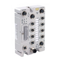
8 Inputs/Outputs – 0.5 A (8xM12)
Brand:
Bosch
| Category:
I/O Systems
| Size: 5.7 MB
Table of Contents
Table of Contents
3
1 About this Documentation
7
General Information
7
Scope
7
Validity of the Documentation
8
Structuring the Documentation
9
Terms and Abbreviations
10
Customer Feedback
10
2 Important Instructions on Use
11
Intended Use
11
Introduction
11
Use and Application Cases
11
Unintended Use
12
3 Using Safety Instructions
13
Safety Instructions - Structure
13
Explaining Signal Words and Safety Alert Symbol
13
Symbols Used
14
4 Device Description
15
General Information
15
Connections
16
Labeling Options and Mounting
17
Display Elements
18
Labeling and Symbols at Rear Side
19
Type Plate
20
Schematic Diagram
20
Dimensions
22
Technical Data
22
Device Data
22
Module Supply
23
Communication
23
Digital Inputs
23
Input Characteristic Curve
24
Digital Outputs
24
Actuator Selection Specifications
24
Effect of Operating States
25
Counters 1 and 2 (Parameterizable)
25
Parameterizable Functions
25
Parameterizable Functions of Counters
26
Diagnostics
27
Process Image
27
Displays
27
Electrical Isolation
27
Standards and Approvals
28
5 Mounting the Module
29
General Information
29
Mounting Notes
29
Required Tools and Accessories for Mounting
29
Direct Mounting to the System
30
Mounting on Carrier Rail (Only with Bosch Rexroth Accessories)
30
Fastening Carrier Rail Adapter on the Module
30
Fastening the Module with Mounting Rail Adapter to a Mounting Rail
31
Mounting on Profile Rail (Only with Bosch Rexroth Accessories)
32
Fastening Profile Adapter on the Module
32
Fastening the Module with Profile Adapter on Profile Rail
33
Replacing the Labeling Fields
33
Mounting the Spacer in Case of Compact Arrangement
34
6 Connecting Data and Supply Cables
37
Notes
37
Required Accessories
38
Connecting S-BUS
38
Connecting Supply Cables
39
Connecting Sensor/Actuator Cables
41
7 Commissioning
45
General Information
45
8 Parameterization
47
General Information
47
Diagnostic Overview
47
Input and Output Parameters
48
Operation Mode "DO Module
49
Operation Mode "DI Module
50
Operation Mode "DIO Module
50
Operation Mode "DIO Module with Counter
51
Global Settings for Field Supply
52
Automatic Storage of System Parameters
52
Firmware Update
53
9 Process Images
55
General Information
55
DO Operation Mode
56
Input Data
56
Output Data
56
DI Operation Mode
57
Input Data
57
Output Data
58
DIO Operation Mode
58
Input Data
58
Output Data
59
DIO Operation Mode + 1 Counter
60
Input Data
60
Output Data
62
DIO Operation Mode + 2 Counter
63
Input Data
63
Output Data
64
10 Counter Function
65
General Information
65
Counter Control Via Inputs and Outputs
65
Controlling and Monitoring Counter Via Process Data
66
General Information
66
Control Byte
66
Status Byte
67
Control Example of Two Counters Via Process Data
68
11 Diagnostics Via LED Signals
71
General Information
71
Operating Messages of the Module
71
12 Maintenance and Service
75
General Information
75
Replacing the Module
75
Disconnecting the Wiring
75
Removing the Field Bus Coupler from the System
75
Removing the Field Bus Coupler from the Carrier Plate
75
Removing the Field Bus Coupler from the Profile Adapter
76
Connecting the Module
76
Disposal
76
13 Using Interference-Free Module in Safety Applications
77
General Information
77
Important Instructions
77
General Measures and Requirements for the Module Supply Concept
78
Measures and Requirements for Shielded Voltage Supply of the Module
79
Measures and Requirements for Unshielded Voltage Supply of the Module
80
Connecting the Module to Safety Control Devices
80
General Structure of a Potential Group
80
Connection Samples
81
14 Accessories
83
General Information
83
Assembled S-BUS Cables
83
Ready-Made Supply Cables
85
Carrier Rail Adapter, Profile Adapter and Spacer
86
End Clamp
87
Protective Caps
87
Module Labeling Strips
87
15 Appendix
89
Diagnostic Information
89
16 Service and Support
91
Index
93
Bosch Rexroth IndraControl S67 Series Application Description (88 pages)
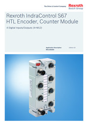
HTL Encoder, Counter Module
Brand:
Bosch
| Category:
Media Converter
| Size: 3.82 MB
Table of Contents
Table of Contents
3
1 About this Documentation
7
General Information
7
Scope
7
Validity of the Documentation
8
Structuring the Documentation
9
Terms and Abbreviations
10
Customer Feedback
10
2 Important Instructions on Use
11
Intended Use
11
Introduction
11
Use and Application Cases
11
Unintended Use
12
3 Using Safety Instructions
13
Safety Instructions - Structure
13
Explaining Signal Words and Safety Alert Symbol
13
Symbols Used
14
4 Device Description
15
General Information
15
Connections
17
Labeling Options and Mounting
18
Display Elements
19
Labeling and Symbols at Rear Side
20
Type Plate
20
Schematic Diagram
21
Dimensions
23
Technical Data
23
Device Data
23
Module Supply
23
Communication
24
Incremental Encoder Interface
24
Counter Interface
24
Digital Inputs
25
Input Characteristic Curve
25
Digital Outputs
26
Actuator Selection Specifications
26
Effect of Operating States
27
Parameterizable Functions of the Incremental Encoder Interfaces
27
Parameterizable Functions of the Counter Interfaces
27
Parameterizable Functions of the Cam Outputs
27
Parameterizable Functions of the PWM Outputs
28
Parameterizable Functions of the Digital Inputs and Outputs
28
Diagnostics
28
Process Image
28
Displays
28
Electrical Isolation
29
Standards and Approvals
29
5 Mounting Module
31
General Information
31
Mounting Notes
31
Required Tools and Accessories for Mounting
31
Direct Mounting to System
32
Mounting on Mounting Rail (Only with Bosch Rexroth Accessories)
32
Fastening Mounting Rail Adapter at Module
32
Fastening Module with Mounting Rail Adapter to Mounting Rail
33
Mounting on Profile Rail (Only with Bosch Rexroth Accessories)
34
Fastening Profile Adapter on Module
34
Fastening Module with Profile Adapter to Profile Rail
34
Replacing Labeling Fields
35
Mounting Spacer in Case of Compact Arrangement
35
6 Connecting Data and Supply Cables
39
Notes
39
Required Accessories
40
Connecting S-BUS
40
Connecting Supply Cables
41
Connecting Interface Cables
43
Connecting Sensor/Actuator Cables
44
7 Commissioning
47
General Information
47
8 Parameterization
49
General Information
49
Diagnostic Overview
49
Counter Parameters
51
Cam Parameters
53
Pulse Width Modulation Parameters
54
Input and Output Parameters
54
Global Settings for Field Supply
55
Field Supply Parameters
55
Automatic Storage of System Parameters
56
Firmware Update
56
9 Process Images
57
General Information
57
Input Data
57
Output Data
59
10 Counter Function
63
General Information
63
Operation Modes
63
Controlling and Monitoring the Counter Via Process Data
64
General Information
64
Status Bytes
64
Control Bytes
66
Example to Control Two Counters Via the Process Data
68
11 Diagnostics Via LED Signals
69
Operating Messages of the Module
69
12 Maintenance and Service
73
General Information
73
Replacing Module
73
Disconnecting Wiring
73
Removing Module from System
73
Removing Module from Mounting Rail
73
Removing Module from Profile Adapter
74
Connecting Module
74
Disposal
74
13 Accessories
75
General Information
75
Assembled S-BUS Cables
75
Ready-Made Supply Cables
77
Carrier Rail Adapter, Profile Adapter and Spacer
78
End Clamp
78
Protective Caps
79
Module Labeling Strips
79
14 Appendix
81
Diagnostic Information
81
15 Service and Support
83
Index
85
Advertisement
Bosch Rexroth IndraControl S67 Series Manual (82 pages)
Digital Module High Speed 4 Inputs/Outputs – 0.2 A (4×M12)
Brand:
Bosch
| Category:
Control Unit
| Size: 3.33 MB
Table of Contents
Table of Contents
3
1 About this Documentation
7
General Information
7
Scope
7
Validity of the Documentation
8
Structuring the Documentation
9
Terms and Abbreviations
10
Customer Feedback
10
2 Important Instructions on Use
11
Intended Use
11
Introduction
11
Use and Application Cases
11
Unintended Use
12
3 Using the Safety Instructions
13
Structure of the Safety Instructions
13
Explaining Signal Words and Safety Alert Symbol
13
Symbols Used
14
4 Device Description
15
General Information
15
Connections
16
Labeling Options and Mounting
17
Display Elements
18
Labeling and Symbols at Rear Side
19
Type Plate
19
Schematic Diagram
20
Dimensions
21
Technical Data
21
Device Data
21
Module Supply
21
Communication
22
Digital Inputs
22
Input Characteristic Curve
23
Digital Outputs
23
Actuator Selection Specifications
23
Effect of Operating States
23
Counters (Parameterizable)
24
Parameterizable Functions
24
Parameterizable Counter Functions
25
Diagnostics
26
Process Image
26
Displays
26
Electrical Isolation
26
Standards and Approvals
27
5 Mounting the Module
29
General Information
29
Mounting Notes
29
Required Tools and Accessories for Mounting
29
Direct Mounting to the System
30
Mounting on Carrier Rail (Only with Bosch Rexroth Accessories)
30
Fastening Carrier Rail Adapter on the Module
30
Fastening the Module with Mounting Rail Adapter to a Mounting Rail
31
Mounting on Profile Rail (Only with Bosch Rexroth Accessories)
32
Fastening Profile Adapter on the Module
32
Fastening the Module with Profile Adapter on Profile Rail
33
Replacing the Labeling Fields
33
Mounting the Spacer in Case of Compact Arrangement
34
6 Connecting Data and Supply Cable
37
Notes
37
Required Accessories
38
S-BUS Connection
38
Supply Cable Connection
39
Connecting the Sensor/Actuator Cable
41
7 Commissioning
43
General Information
43
8 Parameterization
45
General Information
45
Diagnostic Overview
45
Input and Output Parameters
46
Operation Mode "DO Module
47
Operation Mode "DI Module
48
Operation Mode "DIO Module
48
Operation Mode "DIO Module with Counter
50
Global Settings for Field Supply
51
Automatic Storage of System Parameters
51
Firmware Update
51
9 Process Images
53
General Information
53
DO Operation Mode
54
Input Data
54
Output Data
54
DI Operation Mode
55
Input Data
55
Output Data
56
DIO Operation Mode
57
Input Data
57
Output Data
57
DIO Operation Mode + Counter
58
Input Data
58
Output Data
59
10 Counter Function
61
General Information
61
Controlling the Counter Via the Input and Outputs
61
Controlling and Monitoring the Counter Via Process Data
62
General Information
62
Control Byte
62
Status Byte
63
For Example, Controlling the Counter Via the Process Data
64
11 Diagnostics Via LED Signals
65
General Information
65
Operating Messages of the Module
65
12 Maintenance and Service
69
General Information
69
Replacing the Module
69
Disconnecting the Wiring
69
Removing the Field Bus Coupler from the System
69
Removing the Field Bus Coupler from the Carrier Plate
69
Removing the Field Bus Coupler from the Profile Adapter
70
Connecting the Module
70
Disposal
70
13 Accessories
71
General Information
71
Assembled S-BUS Cables
71
Ready-Made Supply Cables
71
Carrier Rail Adapter, Profile Adapter and Spacer
72
End Clamp
73
Protective Caps
73
Module Labeling Strips
73
14 Appendix
75
Diagnostic Information
75
15 Service and Support
77
Index
79
Bosch Rexroth IndraControl S67 Series Application Description (72 pages)
Digital Module 8 Outputs
Brand:
Bosch
| Category:
I/O Systems
| Size: 3.93 MB
Table of Contents
Table of Contents
3
1 About this Documentation
7
General Information
7
Scope
7
Validity of the Documentation
8
Structuring the Documentation
9
Terms and Abbreviations
10
Customer Feedback
10
2 Important Instructions on Use
11
Intended Use
11
Introduction
11
Use and Application Cases
11
Safety Devices
12
Information on the Operation
12
Unintended Use
12
3 Using the Safety Instructions
13
Structure of the Safety Instructions
13
Explaining Signal Words and Safety Alert Symbol
13
Symbols Used
14
4 Device Description
15
General Information
15
Connections
15
Labeling Options and Mounting
16
Display Devices
17
Labeling and Symbols at Rear Side
18
Type Plate
18
Schematic Diagram
19
Dimensions
20
Technical Data
20
Device Data
20
Module Supply
20
Communication
21
Digital Outputs
21
Actuator Selection Specifications
21
Effect of Operating States to Output
22
Electrical Isolation
22
Parameterizable Functions
22
Diagnostics I/O
22
Process Image
23
Displays
23
Standards and Approvals
23
5 Mounting Module
25
General Information
25
Mounting Notes
25
Required Tools and Accessories for Mounting
25
Direct Mounting to System
26
Mounting on Mounting Rail (Only with Bosch Rexroth Accessories)
26
Fastening Mounting Rail Adapter at Module
26
Fastening Module with Mounting Rail Adapter to Mounting Rail
27
Mounting on Profile Rail (Only with Bosch Rexroth Accessories)
28
Fastening Profile Adapter on Module
28
Fastening Module with Profile Adapter to Profile Rail
29
Replacing Labeling Fields
29
Mounting Spacer in Case of Compact Arrangement
30
6 Connecting Data and Supply Cables
33
Notes
33
Required Accessories
34
Connecting S-BUS
34
Connecting Supply Cables
35
Connecting Actuator Cables
37
7 Commissioning
39
General Information
39
8 Process Images
41
General Information
41
Output Data
41
Input Data
42
9 Parameterization
45
General Information
45
Diagnostic Overview
45
Output Parameters
46
Global Settings for Field Supply
47
Automatic Storage of System Parameters
47
Firmware Update
47
10 Diagnostics Via LED Signals
49
General Information
49
Operating Messages of the Module
49
11 Maintenance and Service
53
General Information
53
Replacing Module
53
Disconnecting Wiring
53
Removing Module from System
53
Removing Module from Mounting Rail
53
Removing Module from Profile Adapter
54
Connecting Module
54
Disposal
54
12 Using Feedback-Free Module in Safety Applications
55
General Information
55
Important Information
55
General Measures and Requirements for the Module Supply Concept
56
Measures and Requirements for Shielded Module Voltage Supply
57
Measures and Requirements for Unshielded Module Voltage Supply
58
Connecting Module to Safety Control Devices
58
General Structure of a Potential Group
58
Connection Examples
59
13 Accessories
61
General Information
61
Assembled S-BUS Cables
61
Ready-Made Supply Cables
61
Carrier Rail Adapter, Profile Adapter and Spacer
62
End Clamp
63
Protective Caps
63
Module Labeling Strips
63
14 Appendix
65
Diagnostic Information
65
15 Service and Support
67
Index
69
Bosch Rexroth IndraControl S67 Series Application Description (64 pages)
Digital Module High Speed 8 Outputs
Brand:
Bosch
| Category:
Control Unit
| Size: 3.18 MB
Table of Contents
Table of Contents
3
1 About this Documentation
7
General Information
7
Scope
7
Validity of the Documentation
8
Structuring the Documentation
9
Terms and Abbreviations
10
Customer Feedback
10
2 Important Instructions on Use
11
Intended Use
11
Introduction
11
Use and Application Cases
11
Safety Devices
12
Information about the Operation
12
Unintended Use
12
3 Using the Safety Instructions
13
Structure of the Safety Instructions
13
Explaining Signal Words and Safety Alert Symbol
13
Symbols Used
14
4 Device Description
15
General Information
15
Connections
15
Labeling Options and Mounting
16
Display Elements
17
Labeling and Bar Code Type at the Back of the Device
18
Type Plate
18
Schematic Circuit Diagram
19
Dimensions
20
Technical Data
20
Device Data
20
Module Supply
20
Communication
21
Digital Outputs
21
Specification for Actuator Selection
21
Influence of Operating States to the Output
22
Electrical Isolation
22
Parameterizable Functions
22
Diagnostic I/O
22
Process Image
22
Displays
23
Standards and Approvals
23
5 Mounting the Module
25
General Information
25
Mounting Notes
25
Required Tools and Accessories for Mounting
25
Direct Mounting to the System
26
Mounting on Carrier Rail (Only with Bosch Rexroth Accessories)
26
Fastening Carrier Rail Adapter on the Module
26
Fastening the Module with Mounting Rail Adapter to a Mounting Rail
27
Mounting on Profile Rail (Only with Bosch Rexroth Accessories)
28
Fastening Profile Adapter on the Module
28
Fastening the Module with Profile Adapter on Profile Rail
29
Replacing the Labeling Fields
29
Mounting the Spacer in Case of Compact Arrangement
30
6 Connecting Data and Supply Cable
33
Notes
33
Required Accessories
34
S-BUS Connection
34
Supply Cable Connection
35
Connecting the Actuator Cable
37
7 Commissioning
39
General Information
39
8 Process Images
41
General Information
41
Output Data
41
Input Data
42
9 Parameterization
43
General Information
43
Diagnostic Overview
43
Input Parameters
44
Global Settings for Field Supply
45
Automatic Storage of System Parameters
45
Firmware Update
45
10 Diagnostics Via LED Signals
47
General Information
47
Operating Messages of the Module
47
11 Maintenance and Service
51
General Information
51
Replacing the Module
51
Disconnecting the Wiring
51
Removing the Field Bus Coupler from the System
51
Removing the Field Bus Coupler from the Carrier Plate
51
Removing the Field Bus Coupler from the Profile Adapter
52
Connecting the Module
52
Disposal
52
12 Accessories
53
General Information
53
Assembled S-BUS Cables
53
Ready-Made Supply Cables
53
Carrier Rail Adapter, Profile Adapter and Spacer
54
End Clamp
55
Protective Caps
55
Module Labeling Strips
55
13 Appendix
57
Diagnostic Information
57
14 Service and Support
59
Index
61
Advertisement
Related Products
Bosch Rexroth IndraControl S67-S3-BK-DI8-M8
Bosch Rexroth IndraControl S67-DO8-M12-2A
Bosch Evolution SHE43P22UC
Bosch SHE43R55UC/64
BOSCH SHE4AP02UC-03
BOSCH SHE43F16UC/60
Bosch SHX36L05UC-18
Bosch SHU4036
Bosch SHU66C06
Bosch SHX5AL06UC
Bosch Categories
Dishwasher
Washer
Oven
Power Tool
Dryer
More Bosch Manuals
Login
Sign In
OR
Sign in with Facebook
Sign in with Google
Upload manual
Upload from disk
Upload from URL