Sign In
Upload
Manuals
Brands
ABB Manuals
Media Converter
ACS880-1604LC
ABB ACS880-1604LC Manuals
Manuals and User Guides for ABB ACS880-1604LC. We have
2
ABB ACS880-1604LC manuals available for free PDF download: Hardware Manual
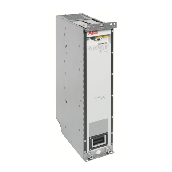
ABB ACS880-1604LC Hardware Manual (298 pages)
DC/DC converter modules
Brand:
ABB
| Category:
Control Unit
| Size: 39.87 MB
Table of Contents
Table of Contents
5
Introduction to the Manual
15
Contents of this Chapter
15
Applicability
15
Safety Instructions
15
Target Audience
15
Categorization by Frame Size and Option Module
16
Use of Component Designations
16
Terms and Abbreviations
16
Related Documents
17
Operation Principle and Hardware Description
19
Contents of this Chapter
19
Operation Principle
19
Main Circuit Diagram
19
Overview Diagram of a Drive with a DC/DC Converter Unit
23
Single-Line Circuit Diagram of the DC/DC Converter Unit
24
Converter Module Hardware
25
Frame R7I
25
Module Layout
25
Coolant Connectors
25
Installation Frame
26
Connectors X50, X52 and X53; Auxiliary Voltage Selector X59
26
Fiber Optic Connectors
28
Leds
28
Frame R8I
29
Module Layout
29
Coolant Connectors
29
Connectors X50
30
Fiber Optic Connectors
31
Leds
31
DC Bus Connection and Capacitor Charging
32
BDCL Filter Module
33
BDCL Filter Module for Frame R7I Converter Module
33
BDCL Filter Module for Frame R8I Converter Module
34
Overheating Protection of the Filter
34
Control Unit
34
Overview of the Control Connections of the BCU Control Unit
35
Overview of the Control Connections of the UCU Control Unit
36
Converter Unit Control Devices
36
DC Switch-Disconnector
36
Charging Switch
37
Door Lights
37
Control Unit
37
Control Panel [A59]
37
PC Connection
38
Fieldbus Control
38
BAMU Voltage/Current Measurement Unit
38
I/O Module
38
Type Designation Labels
39
Type Designation Labels of the DC/DC Converter Module
39
Type Designation Label of the BDCL Filter Module
40
Type Designation Key
40
Type Designation Key of the Converter Module
40
Type Designation Key of the Filter Module
41
Moving and Unpacking the Module
43
Contents of this Chapter
43
Cabinet Construction
45
Contents of this Chapter
45
Limitation of Liability
45
North America
45
Energy Storage
45
Liquid Pipe Connector Installation Instructions
45
Cabinet Configuration Overview
48
Frame R7I Without DC Switch-Disconnector
48
Frame R7I with DC Switch-Disconnector
49
Frame R8I
50
Installation Examples
51
R7I DC/DC Converter Module in Rittal VX25 Enclosure
52
Layout with DC Switch-Disconnector and Charging
52
Layout Without DC Switch-Disconnector and Charging
53
Pipe Routing Example
54
Installation Stages
55
Kits for ACS880-1604LC R7I Unit in Rittal VX25 Cabinets
57
Stage 1: Installation of Common Parts
58
Stage 2: Side Plates Kit Installation
59
Stage 3: BDCL Filter Mounting Mechanics Kit and Output Busbar Kit Installation
60
Stage 4: Cooling Components Kit and Filter to Module Busbars Installation
61
Stage 5: Heat Exchanger and Fan Mechanics Installation
62
Stage 6: BDCL Filter Installation
63
Stage 7: Installation Frame Kit and DC Busbar Kit Installation
64
Stage 8A: Busbar Kits for Fuse Only Solution (Unit Without DC Switch)
65
Stage 8B: Busbar Kits for DC Switch Solution (Unit with DC Switch)
66
Stage 9: Module Installation
67
Stage 10: Swing-Out Frame and Shroud Kit Installation
68
Stage 11: Marine Kit Installation
69
Stage 12: Pressure Relief Vent Kit and Cabinet Cover Installation
70
2×R7I DC/DC Converter Modules in Rittal VX25 Enclosure
71
Parallel Connection
71
R8I DC/DC Converter Module in Rittal VX25 Enclosure
72
Layout with DC Switch/Disconnector and Charging
72
Layout Without DC Switch/Disconnector and Charging
73
Pipe Routing Example
74
Installation Stages
75
Kits for ACS880-1604LC R8I Unit in Rittal VX25 Cabinets
77
Stage 1: Installation of Common Parts
78
Stage 2: Side Plates, Busbars and Quick Connectors for Connecting DDC
79
Module and Filter
79
Stage 3: Module Installation Parts
80
Stage 4: DDC and Energy Storage Connection
81
Stage 5A: DC Connection with Charging
82
Stage 5B: DC Connection Without Charging
83
Stage 6: Cooling Components
84
Stage 7: DDC Module and Filter Installation
85
Stage 8: Swing Frame and Shroud Installation
86
2×R8I DC/DC Converter Modules in Rittal VX25 Enclosure
87
Parallel Connection
87
Generic Enclosures
88
Guidelines for Planning Electrical Installation
89
Contents of this Chapter
89
Limitation of Liability
89
North America
89
Generic Guidelines
89
Selecting the Energy Storage
90
Implementing Protections for the Energy Storage
91
General Principles
91
Selecting a Protective Device for the Energy Storage
91
Energy Storage Disconnecting (Isolating) Device
91
Overload Protection of the System by the DC/DC Converter
91
Protecting the Energy Storage Cable
91
Energy Storage Discharging Device
92
Implementing Earth Fault Protection
92
Implementing an Interlocking between the Disconnecting Devices
92
Selecting and Routing the Energy Storage Cables
92
Cable Selection Procedure
92
Recommended Cables
92
Typical Cable Sizes
93
Minimizing Electromagnetic Interference
93
Maximum Cable Length
93
EMC Compliance of the Complete Installation
93
Parallel Connection
94
Electrical Installation
95
Contents of this Chapter
95
Safety and Liability
95
Electrical Safety Precautions
95
General Notes
97
Printed Circuit Boards
97
Handling Fiber Optic Cables
97
Measuring the Insulation Resistance of the DC Cabling
97
Connecting the Energy Storage Cable and Load Disconnected Indicator Cable
99
Use of Fasteners in Cable Lug Connections
99
Connection Diagram
100
Connection Procedure for Power Connections Inside the DC/DC Converter Cubicle
101
Connection Procedure of the Energy Storage Cables
101
Connecting the BDCL Filter
104
Internal Circuit Diagram for the BDCL Filter
105
Installing the Charging Circuit
105
Connecting the External Power Supply Cable for the Auxiliary Circuit
106
DC/DC Converter Module
106
BDCL Filter Module
106
Connecting the Control Cables
106
Default I/O Connection Diagram
106
Connection Procedure
106
Installing Option Modules
108
Connecting a PC
109
The Control Unit
111
Contents of this Chapter
111
General
111
BCU Layout
112
Ucu-22
114
Default I/O Diagram of the Converter Control Unit (BCU)
117
Default I/O Diagram of the Converter Control Unit (UCU-22
119
Additional Information on the Connections
122
Power Supply for the Control Unit (XPOW)
122
The X485 Connector (BCU)
122
The X485 Connector (UCU)
122
Safe Torque off (XSTO, XSTO OUT)
123
FSO Safety Functions Module Connection (X12, with BCU Only)
123
SDHC Memory Card Slot
123
Microsdhc Memory Card Slot
123
Connector Data
124
BCU Ground Isolation Diagram
127
Ucu-22
128
Installation Checklist
129
Contents of this Chapter
129
Checklist
129
Start-Up
133
Contents of this Chapter
133
Start-Up Procedure
134
Maintenance
137
Contents of this Chapter
137
Maintenance Intervals
137
Description of Symbols
137
Recommended Maintenance Intervals after Start-Up
138
Maintenance Timers and Counters
139
Disconnecting the DC/DC Converter
139
Disconnecting the DC/DC Converter from the Energy Storage
139
Disconnecting the DC/DC Converter from the Drive System with the DC Switch-Disconnector
140
Connecting the DC/DC Converter
140
Fans
140
Frame R7I - Internal Module Fan Replacement
141
Frame R8I Fan Replacement
142
R7I Converter Module
143
Removing the Module
143
Installing the Module
145
R8I Converter Module
146
Replacing an R8I Converter Module
146
Assembling the Service Platform
146
Removing the Module
147
Reinstalling the Module
150
Capacitors
151
Reforming the Capacitors
151
Control Panel
151
Control Unit
151
BCU Control Unit Types
151
UCU Control Unit Types
151
Replacing the Memory Unit (BCU)
151
Replacing the Memory Unit (UCU-22
152
Replacing the BCU Control Unit Battery
153
Replacing the Real-Time Clock Battery (UCU-22
154
Replacing the Microsdhc Memory Card (UCU-22
155
Leds and Other Status Indicators
155
Control Panel and Panel Platform/Holder Leds
156
Converter Module Leds
156
Ordering Information
157
Contents of this Chapter
157
Kit Code Key
157
Frame R7I and Multiples
159
DC/DC Converter Modules
159
BDCL Filters
160
Control Panel
162
Control Electronics
163
Control Unit (UCU)
163
Fiber Optic Cables
163
Control Circuit Plug Connectors
164
Options
164
Mechanical Installation Accessories
165
Module Installation Parts
165
Swing-Out Frame (for Rittal VX25 Enclosures)
167
Shrouds
168
Heat Exchanger Mechanics Kit
168
Bottom Cable Entry
169
Marine Kit
170
Pressure Relief Vent Kit
170
Electrical Installation Accessories
171
Busbars and Quick Connectors for Connecting DC/DC Converter Module and Filter
171
Common DC Flat-PLS Assembly
172
DC Connection with DC Switch-Disconnector and Charging
172
DC Connection Without DC Switch-Disconnector and Charging
174
Energy Storage Connection
175
Input DC Fuses
176
Output DC Fuses
177
Parallel Connection Busbar Kit
178
Cooling System Parts
178
Coolant Distribution Manifold Kits
178
Piping
179
Heat Exchanger
180
Cooling Fan
180
Frame R8I and Multiples
181
DC/DC Converter Modules
181
BDCL Filters
182
Control Panel
183
Control Electronics
184
Control Unit (BCU)
184
Fiber Optic Cables
184
Control Circuit Plug Connectors
185
Options
185
Mechanical Installation Accessories
185
Module Installation Parts
185
Swing-Out Frame (for Rittal VX25 Enclosures)
188
Shrouds
189
Bottom Cable Entry
190
Marine Kit
191
Pressure Relief Vent Kit
191
Electrical Installation Accessories
192
Busbars and Quick Connectors for Connecting DC/DC Converter Module and Filter
192
Common DC Flat-PLS Assembly
193
DC Connection with DC Switch-Disconnector and Charging
193
DC Connection Without DC Switch-Disconnector and Charging
195
Energy Storage Connection
196
Input DC Fuses
197
Output DC Fuses
198
Parallel Connection Busbar Kit
198
Cooling System Parts
199
Coolant Distribution Manifold Kits
199
Piping
200
Heat Exchanger
200
Cooling Fan
200
Miscellaneous
201
BAMU Voltage/Current Measurement Unit
201
I/O Module
201
Internal Cooling Circuit
203
Contents of this Chapter
203
Applicability
203
Internal Cooling System
203
Advertisement
ABB ACS880-1604LC Hardware Manual (200 pages)
DC/DC converter modules
Brand:
ABB
| Category:
Media Converter
| Size: 14.92 MB
Table of Contents
Table of Contents
5
Table of Contents
6
Table of Contents
7
Table of Contents
8
Table of Contents
9
Table of Contents
10
Table of Contents
11
Contents of this Chapter
13
Categorization by Frame Size and Option Module
14
Related Documents
15
17
Contents of this Chapter
17
Main Circuit Diagram
18
Overview Diagram of a Drive with a DC/DC Converter Unit
20
Single-Line Circuit Diagram of the DC/DC Converter Unit
21
Converter Module Hardware
22
Connectors X50...X59
23
Fiber Optic Connectors
24
BDCL Filter Module
25
Overheating Protection of the Filter
26
Overview of the Control Connections of the BCU Control Unit
27
Converter Unit Control Devices
28
PC Connection
29
Type Designation Labels
30
Type Designation Label of the BDCL Filter Module
31
Type Designation Key
32
33
Contents of this Chapter
33
35
Contents of this Chapter
35
Cabinet Configuration Overview
36
Installation Examples
37
R8I DDC Unit in Rittal VX25 Enclosure
38
Layout Without DC Switch/Disconnector and Charging
39
Pipe Routing Example
40
Installation Stages
41
Kits for ACS880-1604LC R8I Unit in Rittal VX25 Cabinets
42
Stage 1: Installation of Common Parts
43
Stage 2: Side Plates, Busbars and Quick Connectors for Connecting DDC Module and Filter
44
Stage 3: Module Installation Parts
45
Stage 4: DDC and Energy Storage Connection
46
Stage 5A: DC Connection with Charging
47
Stage 5B: DC Connection Without Charging
48
Stage 6: Cooling Components
49
Stage 7: DDC Module and Filter Installation
50
Stage 8: Swing Frame and Shroud Installation
51
R8I DDC Unit
52
53
Contents of this Chapter
53
Selecting the Energy Storage
54
Implementing Protections for the Energy Storage
55
Implementing an Interlocking between the Disconnecting Devices
56
EMC Compliance of the Complete Installation
57
59
Contents of this Chapter
59
Electrical Safety Precautions
60
General Notes
61
Checking the Insulation of the Energy Storage Cable
62
Connecting the Power Cables
63
Connection Procedure for Power Connections Inside the DC/DC Converter Cubicle
64
Connection Procedure of the Energy Storage Cables
65
Connecting the BDCL Filter
67
Installing the Charging Circuit
68
Connecting the Control Cables
69
Installing Optional Modules
71
73
Contents of this Chapter
73
75
Contents of this Chapter
75
Start-Up Procedure
76
Disconnecting the DC/DC Converter with DC Switch/Disconnector
79
Reconnecting the DC/DC Converter with DC Switch/Disconnector
80
81
Contents of this Chapter
81
Maintenance Timers and Counters
82
Power Connections
83
Fans
84
DC/DC Converter Module
85
Reinstalling the Module
87
Control Unit
88
Leds and Other Status Indicators
89
91
Contents of this Chapter
91
DC/DC Converter Modules
93
BDCL Filters
94
Control Panel
95
Control Electronics
96
Fiber Optic Cables
97
Mechanical Installation Accessories
98
Swing-Out Frame (for Rittal VX25 Enclosures)
100
Shrouds
101
Bottom Cable Entry
102
Electrical Installation Accessories
103
DC Connection with DC Switch/Disconnector and Charging
105
DC Switch/Disconnector Kits
106
Charging Kits
107
DC Connection Without DC Switch/Disconnector and Charging
108
Energy Storage Connection
109
Output DC Fuses (Energy Storage Side)
110
Cooling System Parts
111
Piping
112
Cooling Fan
113
Miscellaneous
114
115
Contents of this Chapter
115
Connection to a Cooling Unit
117
Filling up and Bleeding the Internal Cooling Circuit
118
Draining the Internal Cooling Circuit
120
Pressure Limits
122
125
Contents of this Chapter
125
Ratings
126
Derating
127
Fuses
128
Dimensions and Weights
129
Typical Power Cable Sizes
130
Tightening Torques
132
Output Power (Energy Storage) Connection
133
Protection Classes
134
Materials
136
Applicable Standards
137
139
Contents of this Chapter
139
BCU-X2 Control Unit Layout and Connections
140
Default I/O Diagram of the Converter Control Unit
142
External Power Supply for the Control Unit (XPOW)
143
The X485 Connector
144
Connector Data
145
BCU-X2 Ground Isolation Diagram
147
149
Contents of this Chapter
149
R8I DC/DC Converter Module
150
151
BDCL Filter Module
151
Quick Connector
152
BCU Control Unit
153
BAMU Voltage/Current Measurement Unit
154
BAMU Accessories
155
Shorting Plug S802-LINK50
156
CIO-01 I/O Module
157
DPMP-01 Door Mounting Kit
158
Switchgear and Charging Components
159
Charging Switches
160
Charging Controller BSFC-12C
161
Handles
162
Contacts
163
DC Fuses
164
165
Contents of this Chapter
165
ACS880-1604LC DC/DC Converter Unit 2×R8I, 3AXD10000873230
166
DDC 1×R8I with DC Switch/Disconnector
167
Sheet 001B (Charging Circuit)
168
Sheet 002A (BDCL Main Circuit)
169
Sheet 005A (Module Connections)
170
Sheet 005B (BDCL Module Connections)
171
Sheet 007A (BAMU Voltage Measurement)
172
Sheet 020A (Auxiliary Voltage Distribution)
173
Sheet 021A (Auxiliary Voltage Distribution)
174
Sheet 022A (24 V DC Distribution)
175
Sheet 026A (Cabinet Fans)
176
Sheet 040A (Control Board)
177
Sheet 040B (Control Board)
178
Sheet 040C (Control Board)
179
Sheet 040D (Signal Lamps)
180
DDC 2×R8I with DC Switch/Disconnector
181
Sheet 001B (Charging Control, 1St Cubicle)
182
Sheet 001C (Main Circuit, 2Nd Cubicle)
183
Sheet 001D (Charging Control, 2Nd Cubicle)
184
Sheet 002A (BDCL Main Circuit, 1St Cubicle)
185
Sheet 002B (BDCL Main Circuit, 2Nd Cubicle)
186
Sheet 005A (Module Connections, 1St Cubicle)
187
Sheet 005B (BDCL Module Connections, 1St Cubicle)
188
Sheet 007A (BAMU Voltage Measurement, 1St Cubicle)
189
Sheet 020A (Auxiliary Voltage Distribution, 1St Cubicle)
190
Sheet 021A (Auxiliary Voltage Distribution, 1St Cubicle)
191
Sheet 022A (Auxiliary Voltage Distribution, 1St Cubicle)
192
Sheet 026A (Cabinet Fan & CIO, 1St Cubicle)
193
Sheet 026B (Cabinet Fan, 2Nd Cubicle)
194
Sheet 040A (Control Board, 1St Cubicle)
195
Sheet 040B (Control Board, 1St Cubicle)
196
Sheet 040C (Control Board, 1St Cubicle)
197
Sheet 040D (Signal Lamps, 1St Cubicle)
198
Advertisement
Related Products
ABB ACS880-1604
ABB ACS880-1607
ABB ACS880-1607LC
ABB ACS880-87LC-4000A/4021A-7
ABB ACS880-87LC-4000A/4132A-7
ABB ACS880-87CC
ABB ACS880-87LC-3200A
ABB ACS880-87LC-3200A-7
ABB ACS880-77CC
ABB ACS800-67LC
ABB Categories
Industrial Equipment
Controller
Measuring Instruments
Battery Charger
DC Drives
More ABB Manuals
Login
Sign In
OR
Sign in with Facebook
Sign in with Google
Upload manual
Upload from disk
Upload from URL