
Related Manuals for Sony PDW-HD1550


Summary of Contents for Sony PDW-HD1550
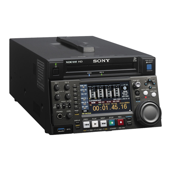
- Page 1 PROFESSIONAL DISC RECORDER PDW-HD1550 OPERATION MANUAL [English] 1st Edition (Revised 1)
-
Page 2: Table Of Contents
Initial Setup ..................25 Front Panel Tilt Mechanism ............26 Connections and Settings ............27 Connections for Content Browser and non-Sony nonlinear editors..27 Connections for cut editing ..............28 Using the editing functions of the recorder (controlling through REMOTE (9P) connector) ............31 Connections for pool coverage............ - Page 3 Loading and unloading a disc .............. 43 Formatting a disc ................. 43 Handling Memory Cards ............... 44 About memory cards................44 Handling External Storage............45 Using external storage ................. 45 Removing external storage ..............46 Chapter 4 Recording, Playback and Copy Recording..................
- Page 4 EDL Editing ..................69 What is EDL editing? ................69 Creating and editing EDLs ..............70 Disc Operations ................73 Checking the disc information ............73 Formatting (initializing) discs ............. 73 Finalizing discs..................73 Repairing discs ..................74 Chapter 6 File Operations Overview..................
- Page 5 Operating hours meter ............... 112 Troubleshooting ................114 Alarms....................114 Error messages................... 121 Specifications ................122 Using UMID Data................126 Ancillary Data................128 Ancillary data in HDSDI/SDSDI signals .......... 128 Ancillary data in MXF files............... 128 Closed caption data................129 Trademarks and Licenses ............
-
Page 6: Chapter 1 Overview
Uncompressed PCM recording of 24-bit 48 kHz audio enables 8-channel audio recording at high sound quality. The PDW-HD1550 (hereinafter, the “unit”) is a 1) Installation of the optional XDBK-106 is required. Professional Disc recorder that supports Full HD (1920 ×... -
Page 7: Usability Features
Supports SNMP for maintenance and service segment from a selected essence mark to the next This unit supports Sony’s SNMP-based remote essence mark. The selection range is divided into 12 maintenance and monitoring software. This software... - Page 8 Canada http://www.sonybiz.ca Latin America http://sonypro-latin.com Europe http://www.pro.sony.eu/pro Middle East, Africa http://sony-psmea.com Russia http://sony.ru/pro/ Brazil http://sonypro.com.br Australia http://pro.sony.com.au New Zealand http://pro.sony.co.nz Japan http://www.sonybsc.com Asia Pacific http://pro.sony-asia.com Korea http://bp.sony.co.kr China http://pro.sony.com.cn India http://pro.sony.co.in Sony Creative Software, software download page: http://www.sonycreativesoftware.com/download/ software_for_sony_equipment Features...
-
Page 9: System Configurations
System Configurations Professional Disc PDW-700/PMW-500 PDW-F1600 BP-L80S Battery Pack RM-280 Editing BKP-L551 Battery Controller Adaptor DC power source AC power source BVE-700 Headphones SD video monitor HD video monitor HDW-2000 series Audio monitor PDW-F75 Laptop computer a) For HDW-2000 series only. The unit can function as a player only when performing linear editing. -
Page 10: Chapter 2 Names And Functions Of Parts
Names and Functions of Parts Chapter Front Panel The names and symbols of buttons and knobs on the front Orange: Function when the button is operated with the panel are color coded according to function. SHIFT button held down. White: Function when the button or knob is operated Blue: Function related to thumbnail operations. -
Page 11: Access Indicator
b Remote control switch 1 Disc control section Different positions of the switch allow different operations as follows. NET: Enables access to the network. When an external network device is being accessed, operations of the buttons and dials related to recording and playback 4 EJECT/USB DRV OFF are disabled. - Page 12 a CH-1/ALL CH, CH-2 to CH-4 (audio level) You can delete essence marks on the chapter thumbnail adjustment knobs screen (see page 67). Depending on the setting of the VARIABLE switch, these b IN indicator and OUT indicator adjust the input audio or playback audio levels of channels 1 to 4.
-
Page 13: Menu Button
c Jog/shuttle transport indicators c PUSH SET knob These show the playback direction in jog, shuttle, or Use for setting menu items and for operations using variable mode. thumbnails on clip list screens. Turn the knob to select items, and press it to confirm the selection. This button is d Shuttle dial also used to set numerical values, such as timecodes. -
Page 14: Play Button
j PAGE/HOME button Displaying the last frame of the last clip: Hold down the When pressed alone, this functions as the PAGE (page SHIFT button, and press this button. switching) button. When pressed together with the SHIFT 2) When setup menu item 153 FIND MODE is set to “clip & rec start mark”, button, functions as the HOME button. -
Page 15: Display Screen
Display screen Basic operation screen 1 Function menu 2 Audio input display/audio level meters 3 System information 4 Disc status indicator 5 Recording/playback format 6 Clip information 7 Status indicator 8 Time data display area 9 Status display area a Function menu b Audio input display/audio level meters Use the PAGE/HOME button to display this menu, and to Displays information about audio. - Page 16 A Input signal indicator: Displays the audio input SD REF: SD-format reference signal signal. B Video input indicator: Displays the selected video input signal. Display Input signal HD-SDI: HDSDI video input SD-SDI: SDSDI video input ANA-1 Analog audio signal Channel 1, 3, 5, 7 or (MIC-1) SG: Test video signal from the internal signal Channel 1, 5...
- Page 17 h Time data display area Icon Status The available recordable resource space is Yellow bar A Remaining disc capacity for recording or playback running out. B REC RUN/FREE RUN C Timecode generator mode There is no available recordable resource Red bar D VITC space on the disc.
- Page 18 set with DF/NDF on page P4 TC of the function menu Display Current setup menu settings (see page 41). BANK1 Same as those in menu bank 1. Display Frame count mode BANK2 Same as those in menu bank 2. DF (drop-frame mode) BANK3 Same as those in menu bank 3.
- Page 19 You can disable the status display area with the DISPLAY button. However, it is automatically enabled when: • Display of error/warning/alarm message becomes necessary. • During battery-driven operation, the power source indicator starts flashing (the battery near end alarm is given). Front Panel...
-
Page 20: Rear Panel
REMOTE (9P) (remote control 9-pin) connector item 028 HD CHARACTER. (D-sub 9-pin) To treat the input and output signals of these connectors as Connect a controller that supports the RS-422A Sony 9-pin non-audio signals, set maintenance menu item M372 VTR control protocol. NON-AUDIO INPUT. - Page 21 1 Power supply section The audio signals of the channels selected with MONITR L and MONITR R on the HOME page of the function menu are output. 1 POWER switch You can superimpose timecodes, menu settings, and error 2 - AC IN connector messages on the HDMI output using the CHAR SEL setting on the HOME page of the function menu.
- Page 22 Microphone settings See “Basic Operations of the Function Menu” (page 39) If you have connected a microphone to this unit, you can for more information about the MONITR L and set input level, AGC, and limiter values for the MONITR R settings. microphone with setup menu items 834, 839, 840, and 841.
-
Page 23: Chapter 3 Preparations
This unit can be powered by AC power, DC power, or a operation manual for the battery charger. battery pack. For safety, use only the Sony battery packs listed below. Notes about battery usage Lithium-ion battery pack: BP-L80S • As long as a battery is connected to the unit, electric... - Page 24 Checking the remaining battery power Attach the BKP-L551 to the side panel. You can use the LEDs on the side panel of the battery to check the remaining power of the battery. When the remaining battery power decreases substantially and the voltage approaches the set shutdown voltage, the power source icon starts flashing in the status display area of the display screen (the battery near end alarm is given).
-
Page 25: Initial Setup
Turn the PUSH SET knob to select the system Initial Setup frequency. This unit is shipped with the system frequency, and current date and time still unset. Therefore, you need to make initial setup settings before using the unit. (You cannot use the unit without setting it up.) Once the unit has been set up, the settings are retained even when the unit is powered off. -
Page 26: Front Panel Tilt Mechanism
To change the angle of the front panel Front Panel Tilt To change the angle to position 2 from position 1, pull the front panel out to position 2. Mechanism To change the angle to position 1 from position 2, first unlock the front panel by pulling it all the way out to the return position. -
Page 27: Connections And Settings
You can Network cable also access this unit from a nonlinear editor that is not a (not supplied) Sony product via FTP/CIFS, and use this unit as a material server. For an overview and installation of Content Browser, (network) access the Sony website closest to your area. -
Page 28: Connections For Cut Editing
2: 9-pin remote control cable (not supplied) HD video monitor 3: HDMI cable (not supplied) Use of an optional Sony HDMI cable is recommended. a) You can use setup menu item 161 (see page 93) to set which signal to output from the HDMI OUT... - Page 29 HDW-M2000 (recorder) settings BVE-700/700A (editing control unit) setting Settings on this unit REMOTE 1 (9P) button: Lit SYNCHRONIZE menu: OFF Remote control switch: REMOTE (see page 11) REF.VIDEO INPUT connector 75 Ω termination Setup menu item 214 switch: OFF REMOTE INTERFACE: 9PIN Audio selection function switching button INPUT button: HDSDI...
- Page 30 2: 9-pin remote control cable (not supplied) HD video monitor 3: HDMI cable (not supplied) Use of an optional Sony HDMI cable is recommended. a) You can use setup menu item 161 (see page 93) to set which signal to output from the HDMI OUT...
-
Page 31: Using The Editing Functions Of The Recorder (Controlling Through Remote (9P) Connector)
3: HDMI cable (not supplied) connector: the same signal as the HDSDI OUTPUT 2 (SUPER) connector output, or the HDSDI signal and thumbnails view signal by automatically switching Use of an optional Sony HDMI cable is recommended. between them. Connections and Settings... -
Page 32: Connections For Pool Coverage
Camcorder connected. HDSDI REMOTE I/F on Remote control switch: page CAM CONFIG 1 of REMOTE (see page 11) the MAINTENANCE menu: PDW-HD1550 (this unit) Setup menu item 214 PDW-700 other than OFF REMOTE INTERFACE: SDI To SDI OUT 1 connector... -
Page 33: Synchronization Reference Signals
Synchronization Reference Signals The synchronization reference signal generator of this unit setting of OUT REF on the HOME page of the function synchronizes to a reference signal input to the REF. menu, and on the type of the selected input signal. Video VIDEO INPUT connector or to a video input signal. -
Page 34: Setting The System Frequency
Setting the System Setting the Timecode Frequency There are the following four ways of recording timecode: Internal Preset mode: This records the output of the This unit can record and play back video at the system internal timecode generator, set beforehand to an frequencies of 1080/59.94i, 50i, 29.97P, 25P, 23.98P or initial value. - Page 35 Setting user bits The first digit of the time data display starts flashing. You can record up to eight hexadecimal digits of information (date, time, event number, etc.) on the timecode track. Select UB by pressing the CNTR SEL function button (F2) in step 1 of “Setting an initial timecode value”...
-
Page 36: Superimposed Text Information
Make the following settings on page P4 TC of the Superimposed Text function menu. • Set TCG to “SDI”. Information • Set PRST/RGN to “TC”. Executing either of these procedures starts the internal The video signal output from the COMPOSITE OUTPUT timecode generator running in synchronization with the 2 (SUPER) connector, SDSDI OUTPUT 2 (SUPER) external timecode generator. -
Page 37: Operation Mode
a Type of time data Display Operation mode Display Meaning Block A Block B Counter data PLAY Playback mode (servo unlocked) TC reader timecode PLAY LOCK Playback mode (servo locked) TC reader user bits data Record mode (servo unlocked) TCR. VITC reader timecode LOCK Record mode (servo locked) - Page 38 • Do not store for long periods under high temperatures or Display Name Description in locations exposed to direct sunlight. Disc This appears during cache exchange recording. If playback conditions have deteriorated cache If a yellow or red playback condition mark appears, the For details, see page 50.
-
Page 39: Basic Operations Of The Function Menu
To change the setting of a function menu Basic Operations of the item Use the function buttons. Function Menu To select the value of the setting item Press the button to the left of each setting item to change The function menu provides access to frequently used the value of the item. -
Page 40: P2 Input Page
Item Setting Item Setting F5: MONITR R Selects the channel to monitor as the right F6: A4 INPUT Selects the audio input signal to assign to monitor channel. audio channel 4. CH1, CH2, CH3, CH4, CH5, CH6, CH7, SDI: Audio signal embedded in the SDI signal CH1/2, CH3/4, CH5/6, CH7/8 (MIX) ANALOG2(MIC2): Input signal to the... -
Page 41: P3 Audio Page
P3 AUDIO page P4 TC page Item Setting Item Setting F1: A5 VOL Sets the volume of audio channel 5. F1: TCG Selects the timecode signal to which the The volume can be adjusted within the internal timecode generator synchronizes. range from –200 to 0 to +200 (–∞... -
Page 42: Handling Discs
Item Setting Handling Discs F4: ADD TO Adds a sub clip to the current EDL (see CURT.EDL page 71). F5: PB/EE Selects the video and audio signals that are output in stop, forward direction high- Discs used for recording and speed search, and reverse direction high- speed search modes. -
Page 43: Notes On Handling
For details, see “Locking (write-protecting) clips” Notes on handling (page 68). Handling The Professional Disc is housed in a cartridge, and is Loading and unloading a disc designed to allow handling free of risk from dust or fingerprints. However, if the cartridge is subjected to a When the on/standby button indicator is lit green, you can severe shock, for example by dropping it, this can result in load and unload a disc as shown in the following figure. -
Page 44: Handling Memory Cards
Memory cards that can be used with this unit Note Use the following Sony memory cards with this unit. Do not touch the write protect switch while an SxS memory card is loaded in a memory card slot. Eject the The memory cards that are supported differ depending on card before setting the write protect switch. -
Page 45: Handling External Storage
The operation of all hard disk drives is not guaranteed. For To mount a USB drive information about recommended devices, consult your Sony dealer. Connect external storage to the Super Speed USB ) connector (USB 3.0 compatible) on the It is possible to create up to 99 folders in external storage. -
Page 46: Removing External Storage
A message appears asking you whether to delete the Note folder. If formatting is executed, all existing partitions (including multipartitions) are deleted and initialized into one single To execute deleting, select “OK” and then press the partition. PUSH SET knob. To cancel deleting, select “CANCEL”... - Page 47 Note The USB drive does not need to be unmounted to remove SxS memory cards or the SBAC-US20/US30 SxS Memory Card USB Reader/Writer. To unmount the USB drive In disc thumbnail view, press the MEDIA SEL button. The display switches to USB drive thumbnail view. Press the USB DRV OFF button.
-
Page 48: Chapter 4 Recording, Playback And Copy
Recording, Playback and Copy Chapter Carrying out recording Recording One recording segment (from the start to the end of recording) is called a “clip”. This section describes video and audio recording on the unit. See page 39 for more information about function menu operations. -
Page 49: Recording With The Hdsdi Remote Control Function
• The maximum number of clips that can be recorded is Recording with the HDSDI remote 1,200. If the disc already contains 1,200 clips, recording control function operation is not possible. (The message “MAX # Clips” appears in the time data display area.) This section describes the settings required for recording in •... -
Page 50: Continuing Recording While Exchanging Discs (Disc Exchange Cache Function)
Display Meaning Note “C” flashes twice Remaining memory capacity: Low This unit begins recording operation about one second per second after the camcorder. An alarm message Remaining memory capacity: appears instead of None (disc full) “C”. Continuing recording while exchanging discs (disc exchange To stop disc exchange cache recording Do any of the following during cache recording. - Page 51 restore the disc using the device last used to record to the recognized as files, and clip contents recorded up to that point are lost. disc. However, this unit has salvage functions which can hold PDW-U1, PDW-U2, losses to the minimum by reconstructing clips on such PDW-1500, PDW-530, PDW-510, PDW-R1, PDW-F70, PDW-F350, PDW-F330, discs.
-
Page 52: Playback
Press the PLAY button to resume playback at the stop Playback position. After recording The unit stops at the position where recording ended. This section describes playback of video and audio on the To play back a clip, press the PREV button to move to the unit. -
Page 53: Playback Operation
The upper row of the time data display area displays the When two or more clips are recorded on the disc, they are original 24-frame timecode, and the lower row displays the played back in continuous playback mode. 30-frame timecode. Note No sound is output when non-audio signals are played back. - Page 54 Press the SHTL/JOG button or VAR/JOG button, Turn the shuttle dial to the desired angle turning it on. corresponding to the desired playback speed. When the SHTL/JOG or VAR/JOG button is pressed Playback in shuttle mode starts. during recording, recording stops and the unit enters The shuttle dial has a detent at the center position, for jog mode.
-
Page 55: Playback Operations Using Thumbnails
This allows you to perform repeat playback, limited to variable playback in the forward direction in the range 0 to +1 times normal speed. Playback operations using thumbnails Playback operations that you can perform with thumbnails include searching for clips, displaying clip information, playing clip lists created, and locking and deleting clips. -
Page 56: Copying
To change the folder for displaying thumbnails Copying Press the FOLDER function button (F3) and select the folder to display thumbnails. Example: To display thumbnails of MPEG-4 AVC/ H.264-format recorded clips, press the FOLDER Overview function button (F3) and select XDROOT. Do one of the following to select the clip to copy. - Page 57 Press the START function button (F5). Copying of the clips starts. The progress of the copying is shown on the Clip Copy screen, and the copy icon lights in the status display area. IN indicator OUT indicator Cue up to the frame where you want to set an OUT To abort the copy operation point.
- Page 58 • Delete the clip in which IN/OUT points are set. • Format the media. Copying...
-
Page 59: Chapter 5 Operations On Clip List Screens
Operations on Clip List Screens Chapter Overview Use clip list screens to search for scenes, play scenes found You can switch between the details view and the by searching, select clips to copy, and perform other thumbnails view of clip list screens. operations related to clips. -
Page 60: Information And Controls On Clip List Screens
• Clip names that are too long are displayed truncated. To Information and controls on clip list view the entire character string of the name, access the screens Clip Properties screen (see page 61). f Video format Thumbnails view The video format of the selected clip is displayed as a combination of the following items. -
Page 61: Edl Mark
1 Clip storage location Frame Rate: The frame rate at the time when the clip was shot. For clips shot using Slow & Quick Motion, the 3 Clip number/total number of clips PB (playback)/Capture (shooting) frame rates are 6 Duration shown. -
Page 62: Expanded Thumbnail Screen
Note When you cue up a clip, the unit always cues up the first frame, even when the index picture has been changed to a different frame. c Clip flag icon Displays the corresponding icon when a clip flag (OK/NG/ KP(KEEP)) is set in the clip (see page 67). - Page 63 g Duration Rec Start essence marks are set automatically at the start of recording, but shot marks can be set at any scene during Displays the time from the first frame of the selected recording or playback. chapter to the first frame of the next chapter. h Scrollbar See page 49 and page 53 for more information about shot mark setting.
-
Page 64: Clip Menu
g Clip date and time Item Sub-item Function Displays the date and time when the clip that contains the Finalize Disc – Finalizes a write-once selected frame was shot and recorded. type Professional Disc. Notes h Clip name • You cannot write Displays the name of the clip that contains the selected additional data to frame. - Page 65 CLIP page NEW EDL command by pressing and holding the SHIFT button and pressing the PUSH SET knob. Item Function For the procedure for creating EDLs, see “Creating and F1: CLP INFO Selects the information to be displayed at editing EDLs” (page 70). the bottom of the thumbnails.
-
Page 66: Clip Operations
On the clip list screen, select the thumbnail of the clip Clip Operations that contains the scene you want to find. Press the PAGE/HOME button to display the function menu, and press the EXPAND function button (F6). Selecting clips The selected clip is divided into 12 blocks, and a list appears on the expanded thumbnail screen (see Select clips with the selection frame (see page 60). -
Page 67: Playing A Clip By Thumbnail Search
Press the PAGE/HOME button to display the function Notes menu, and press the CHAPTER function button (F5). • You cannot switch to the Rec Start essence mark The chapter thumbnail screen (see page 62) appears, thumbnail screen by pressing the DISPLAY button in with thumbnails of the frames where chapters are set. -
Page 68: Locking (Write-Protecting) Clips
To unlock clips The clip flag is set for all selected clips, and the clip flag icon (see page 62) appears on thumbnails. Execute steps 1 to 3 in “To lock clips” (page 68). To clear clip flags Carry out steps 1 to 3, selecting a clip that has a flag set, Select Unlock Selected Clips or Unlock All Clips, and and then select “(none)”... -
Page 69: Copying Clips
Copying clips EDL Editing See “Copy operations” (page 56) for information about operations. What is EDL editing? Setting the index picture frame EDL editing is a function which allows you to select material (clips) from the material recorded on media and perform cut editing. -
Page 70: Creating And Editing Edls
Create EDLs: Use the CREATE NEW EDL command to Clips on a disc create an EDL containing the selected clips. Add sub clips: Use the ADD TO CURT.EDL command Clip 1 Clip 2 Clip 3 Clip 4 to add the clips you want to use to an EDL. You can (C0001) (C0002) (C0003) - Page 71 Display the P1 EDL page of the Clip F menu and press the SET CURT.EDL function button (F1). The selected EDL becomes the current EDL. When the current EDL is specified, the current EDL icon appears in the status display area. Adding on clip list screens See page 59 for information about screen operations.
- Page 72 To play an EDL On the chapter thumbnail screen, select the thumbnail for the sub clip you want to start playing. To start playing from the first frame of the EDL Select the thumbnail for the first sub clip. Press the PLAY button. IN indicator OUT indicator To release the current EDL...
-
Page 73: Disc Operations
Select “Format Media” and press the PUSH SET knob. Disc Operations A confirmation message appears asking you whether to execute formatting. To execute formatting, select “OK” and press the Checking the disc information PUSH SET knob. On a clip list screen, press the MENU button to display The formatting starts, and the message “Format the Clip menu. -
Page 74: Repairing Discs
To finalize another disc Remove the disc that has been finalized, and insert another disc into the disc slot. When the confirmation message appears asking if you want to execute finalizing, execute step 5 once more. To quit finalizing, select “Exit” and press the PUSH SET knob. -
Page 75: Chapter 6 File Operations
File Operations Chapter Overview A remote computer can be connected to this unit and used to operate on recorded data which has been saved in data files, such as video and audio data files. To perform file operations, use either of the following methods to interconnect this unit and a computer. -
Page 76: File Operation Restrictions
File operation restrictions This section explains which operations are possible on Partial write: Write data to a part of the file only. files stored in each directory. When required, the following operation tables distinguish Note reading and writing from partial reading and writing. File names are not case-sensitive. -
Page 77: Edit Directory
a) Only during CIFS connections h) When a C*.MXF file is created, a C*M01.XML file with the same name b) The unit can handle files with user-defined names in the “C*” part. in the “C*” part is created automatically. c) Only files which are 2 seconds or longer in length, in a format matching i) When a C*.MXF file is deleted, a C*M01.XML file and a C*M02.KLV the format (system frequency) and recording format (MPEG HD and file with the same name in the “C*”... -
Page 78: Userdata Directory
a) Only during CIFS connections Notes b) UTF-8 file names can be up to 63 bytes in length. (Depending on the character type, file names (including extension) may be limited to 21 • The maximum number of files that can be created on a characters.) disc is 5,000 for single-layer discs, 6,000 for dual-layer discs, and 20,000 for triple-layer and quad-layer discs... -
Page 79: Ftp File Operations
Making FTP connections FTP File Operations FTP connections between this unit and a remote computer can be made with either of the following. File operations between this unit and a remote computer • The command prompt can be carried out by the File Transfer Protocol (FTP). •... -
Page 80: Command List
Command syntax: STRU <SP> <structure-code> Command syntax: PASS <SP> <password> <CRLF> <CRLF> Input example: PASS pdw-hd1550 <structure-code> can be any of the following. However, for XDCAM, the structure is always “F”, regardless of the QUIT structure-code specification. - Page 81 • B: Block mode Command syntax: RETR <SP> <path-name> <CRLF> • C: Compressed mode Input example: RETR Clip/C0001.MXF Input example: MODE S STOR LIST Begins transfer of a copy of a file in the specified path on Sends a list of files from this unit to the remote computer. the remote computer to the current directory on this unit.
- Page 82 For details, see “File operation restrictions” (page 76). HELP Displays a list of the commands supported by this unit, or Extended commands an explanation of the specified command. Command syntax: HELP <SP> <command-name> In the Command syntax, <SP> means a space, entered by <CRLF>...
-
Page 83: Cifs File Operations
Command syntax: SITE REPFL <SP> <path-name> <SP> CIFS File Operations <start frame> <SP> <transfer size> <CRLF> SITE UMMD You can perform file operations using the Common When preceding the STOR command, this command saves Internet File System (CIFS) between this unit and the the UMID of the copy source file. - Page 84 To break the connections In Windows Explorer, select the network drive and right- click it, then click “Disconnect”. CIFS File Operations...
-
Page 85: Chapter 7 Menus
Menus Chapter Menu System Setup Menu Configuration The setup menu system of this unit comprises the basic setup menu and extended setup menu. The settings for this unit use the following menus. Basic menu This menu is used to make settings related to, for example, Setup menu the operating hours meter, the content and display of text The setup menu system of this unit comprises the basic... -
Page 86: Items In The Basic Menu
Item group Function Refer to Item group Function Refer to Items Settings relating to metadata page 96 Items Settings relating to control page 92 650 to 699 100 to 199 panels Items Settings relating to video page 97 Items Settings relating to the remote page 94 700 to 799 control... - Page 87 Item number Item name Settings LOCAL FUNCTION ENABLE Determine which recording and playback control buttons on the front panel are enabled when this unit is controlled from external equipment. all disable [dis]: All buttons and switches are disabled. stop & eject [st&ej]: Only the STOP button and EJECT button are enabled. all enable [ena]: All buttons and switches are enabled.
- Page 88 Item number Item name Settings HD CHARACTER Specify whether to superimpose text information on the HD video signal. Sub-item HD-SDI2 Specify whether to superimpose text information on the video signal output from the HDSDI OUTPUT 2 (SUPER) connector. off: Do not superimpose. on: Superimpose.
-
Page 89: Basic Menu Operations
Menu control Functions Basic menu operations buttons PUSH SET knob • When turned clockwise or Setup menus are displayed on the display or on a monitor counterclockwise, moves the reverse connected to the HDMI OUT connector. video to select the item to change. •... -
Page 90: Default Settings
Press the RESET button. “time data & status” (factory default setting) is selected. Press the SAVE function button (F5). The setting returned to its factory default is saved in memory as the current setting. To return all settings to their factory default Current setting settings Use the PUSH SET knob or the +/–... -
Page 91: Menu Bank Operations (Menu Items B01 To B13)
Menu bank operations (menu items B01 to B13) You can save menu settings in a menu bank. Menu settings saved in a menu bank can be recalled and used when needed. At startup and after menu ABORT (MENU button) Current settings Save menu and exit (F5 SAVE button) Current bank Recall (B01) -
Page 92: Items In The Extended Menu
Items in the extended menu The following tables show the items in the extended menu. • The underlined values are the factory defaults. • The values in the “Settings” column are the values that appear on settings screens. The values in brackets [ ] are the value shown on menu screens (when they differ from the values shown on settings screens). - Page 93 Menu items in the 100s, relating to the control panels Item number Item name Settings REPEAT MODE Set whether to set repeat playback mode. off: Do not set repeat playback mode. play & VAR fwd [P&VAR]: Perform repeat playback during normal playback and 0 to +1 times normal speed variable playback in the forward direction.
- Page 94 PARA RUN Select whether to use synchronized operation, when you have connected two or more PDW-HD1550 units in a daisy chain or distributed configuration, and are using external control from a VTR or a remote controller such as the RM-280.
- Page 95 Menu items in the 600s, relating to the timecode and metadata Item number Item name Settings VITC POSITION In 59.94i/59.94P/ Select the line into which to insert VITC signals (SD output) SEL-1 29.97P mode 12H to 16H to 20H: Any line from line 12 through line 20. Notes •...
- Page 96 Menu items in the 600s, relating to the timecode and metadata Item number Item name Settings UPCONV EMBEDDED VITC Select the source of the VITC embedded in the output HDSDI signal when up-converting during playback of an SD clip. VITC: Select the VITC of the SD clip. LTC: Select the LTC of the SD clip.
- Page 97 Menu items in the 700s, relating to video control Item number Item name Settings BLANK LINE SELECT Switch blanking of the video output signal on or off for individual lines in the vertical blanking interval. Sub-item The Y/C signal and odd/even fields are blanked simultaneously. ALL LINE - - -: Specify the blanking for each line separately.
- Page 98 Menu items in the 700s, relating to video control Item number Item name Settings VIDEO SETUP REFERENCE Set the video setup amount to be added to the composite output signal. Sub-item OUTPUT LEVEL In 59.94i/59.94P/ Add the setup level selected by this item to the output signal. 29.97P mode 0.0%, 7.5% (UC)
- Page 99 Menu items in the 700s, relating to video control Item number Item name Settings WIDE MODE Specify whether to record and play back with the addition of wide picture information. Sub-item INPUT Select whether to save wide picture information when recording. auto: Automatically save wide picture information when it is detected in the selected input video signal.
- Page 100 Menu items in the 800s, relating to audio control Item number Item name Settings INTERNAL AUDIO SIGNAL Select the operation of the internal audio test signal generator. GENERATOR off: Do not output test signal. silence [silnc]: Silent signal 1kHz sine [1kHz]: 1 kHz, –20 dB FS sine wave signal When you set the INT SG item on page P1 INPUT of the function menu to “ON”, the internal signal generator operates and outputs simultaneous test signals to channels 1 to 8 (see page 40).
- Page 101 Menu items in the 800s, relating to audio control Item number Item name Settings AUDIO AGC/LIMITER MODE For automatic input level adjustments performed on the analog audio signals recorded on channels 1 and 2, select whether to perform the adjustments in stereo mode or independently for channels 1 and 2. mono: Perform automatic adjustments independently for channels 1 and stereo: Perform automatic adjustments in stereo mode.
- Page 102 Menu items in the 900s, relating to digital processing Item number Item name Settings LIMITER (DC) Adjust the down-converter image enhancer. Set the maximum detail level added to emphasize the original signal. 00 (HEX) to 20 (HEX) to 3F (HEX) CRISP (DC) Adjust the down-converter image enhancer.
- Page 103 Menu items in the 900s, relating to digital processing Item number Item name Settings H DETAIL FREQUENCY (UC) Adjust the up-converter image enhancer. Set the center frequency and frequency properties for edge enhancement. 3.2MHz: 3.2 MHz ±1.1 MHz 4.5MHz: 4.5 MHz ±1.4 MHz 5.0MHz: 5.0 MHz ±0.7 MHz 4.0MHz: 4.0 MHz ±2.0 MHz H/V RATIO (UC)
-
Page 104: Maintenance Menu
Maintenance Menu Items in the maintenance menu The following tables show the items in the maintenance • The underlined values are the factory defaults. menu. • The values in the “Setting” column are the values that For details on the menu items that do not appear in this appear in settings screens. - Page 105 M3: OTHERS: Other setting items Item Setting M37: AUDIO M370: HEAD ROOM Select the audio reference level (headroom). CONFIG –20dB, –18dB, –16dB, –12dB, EBUL Note EBUL can be selected only when the system frequency is 50i/25P. M371: DATA LEN Specify the audio channel configuration used during IMX recording. 16bit×8ch [16×8]: 8-channel configuration with 16-bit data width.
- Page 106 M3: OTHERS: Other setting items Item Setting M3B: VANC RX M3B0: VANC RX For setting HD-SDI VANC data input parameters PARAMETER PACKET Notes • In 59.94i, 50i, 29.97P or 25P mode, selecting the line also selects the corresponding line in the second field (for example, if line 9 is selected, line 572 is also selected for VANC packet reception).
- Page 107 M4: SETUP MAINTENANCE: Items relating to the setup menu Item Setting M49: RESET ALL SETUP Reset all the menu settings to the factory settings. Push the SAVE function button (F5): Reset. Push the MENU button: Return to the next highest menu level without resetting. Notes •...
-
Page 108: Maintenance Menu Operations
a) A “jumbo” frame is a frame larger than the maximum 1514 bytes (not including FCS) of the standard Ethernet frame. Jumbo frames make it possible to deliver larger payloads per packet. Since fewer packets need to be routed, packet processing overhead is lower and network throughput is potentially improved. - Page 109 To change network settings The V/MARK1 and v/MARK2 buttons can also be used. To change network settings, carry out the procedure described in “To display the maintenance menu” To return to the factory default setting (page 108) to display the NETWORK menu item, then Press the RESET button.
- Page 110 In the NETWORK menu, press the SAVE function button (F5). When the message “NETWORK CONFIG WAS CHANGED. PLEASE REPOWER.” appears, power the unit off and then on again with the on/standby button. Maintenance Menu...
-
Page 111: Appendix
If you should experience problems with the unit, contact least 99.99%. Thus a very small proportion of pixels may your Sony representative. be “stuck”, either always off (black), always on (red, green, or blue), or flashing. In addition, over a long period... -
Page 112: Condensation
Use the information as a guide in scheduling periodic maintenance. For periodic maintenance, consult a Sony service representative. Display modes of the operating hours meter... - Page 113 To display the operating hours meter Press the MENU button to display the setup menu, then turn the PUSH SET knob to display the required item on the monitor connected to the unit. To exit from the operating hours meter Press the RETURN function button (F1) to return to the setup menu.
-
Page 114: Troubleshooting
Exchg batt! BATTERY NEEDS REPLACING. The battery of the internal clock is low or dead. PLEASE CONTACT SERVICE. Contact your Sony service or sales representative. Run Software Update RUN SOFTWARE UPDATE PROGRAM. The software update is not properly performed. Program. - Page 115 Alarm message in status Alarm message on video monitor Description/action display area screen Over DUR! EXCESSIVE DURATION IS IN DISC. The total amount of recorded data exceeds the capacity of the disc. No Support! FORMAT NOT SUPPORTED. This appears when a disc recorded in an RECORDING AND PLAYBACK IS NOT unsupported recording format has been inserted.
- Page 116 Alarm message in status Alarm message on video monitor Description/action display area screen Unknown FS!(A) CANNOT USE MEDIA(A). The inserted memory card is formatted with an UNSUPPORTED FILE SYSTEM. unsupported file system, or it is not formatted. Format the memory card, or exchange the memory card for one that is formatted with a file system supported by this unit.
- Page 117 Alarm message in status Description/action display area MAX # Clips No more clips can be recorded because the maximum number of recorded clips has been reached. Delete unneeded clips. Media Full! Recording or copying is not possible because the media is full. Delete unneeded clips.
- Page 118 Alarm message in status Alarm message on video monitor Description/action display area screen Disc Damage DISC CANNOT BE RECORDED TO. Use another disc. USE ANOTHER DISC FOR RECORDING. Index File! UNSUPPORT INDEX FILE. DISC CANNOT BE RECORDED TO. Disc Busy! –...
- Page 119 Alarm message on clip Description/action list screen Set Appropriate IN/OUT The settings of IN and OUT points for partial copy operation are invalid. Points. Check the IN and OUT point settings. No Clip! The clip selected for expansion or chapter display has been deleted. Alternatively, the disc has been ejected.
- Page 120 DISC DRIVE LASER 0 LIFETIME HAS The lifetime of the Professional Disc drive laser has ENDED. come to an end. PLEASE CONTACT SERVICE. Contact your Sony service or sales representative. Other alarms Alarm message in status Alarm message on video monitor Description/action...
-
Page 121: Error Messages
Error messages Error codes appear in the status display area when an error (usually a hardware problem) occurs. In addition, both error messages and error codes appear on the video monitor screen. When an error message appears, follow the instructions in the error message to resolve the problem. -
Page 122: Specifications
System Specifications Recording/playback format XAVC (option) General Video MPEG-4 AVC/H.264, Intra CLASS 100 Max. 112 Mbps (for frame frequencies of External dimensions (w/h/d, excluding projections) 59.94i, 50i, 29.97P, 25P) 210 × 132 × 420 mm Max. 98 Mbps (for frame frequencies of ×... -
Page 123: Audio Performance
Recording/playback times Note The actual recording and playback time may differ slightly from the values shown here, depending on usage conditions, etc. Please take the following table on recording and playback time as a guide. Recording formats XAVC AI422 MPEG HD422 MPEG HD MPEG IMX DVCAM... - Page 124 Input connectors Digital audio outputs DIGITAL AUDIO (AES/EBU) OUT 1/2, 3/4 Digital video inputs BNC type (2), channels 1/2, 3/4, SD/HDSDI INPUT complying with AES-3id-1995 BNC type, complying with SMPTE- Analog audio outputs 259M (SD)/SMPTE-292M (HD) ANALOG AUDIO OUTPUT 1, 2 XLR 3-pin, male (2), +4 dBu, 600 Ω...
- Page 125 Design and specifications are subject to change without ANY OTHER REASON WHATSOEVER. notice. • SONY WILL NOT BE LIABLE FOR CLAIMS OF ANY KIND MADE BY USERS OF THIS UNIT OR SONY WILL NOT BE LIABLE FOR DAMAGES OF MADE BY THIRD PARTIES.
-
Page 126: Using Umid Data
Using UMID Data What is a UMID? Metadata is additional information recorded on discs along with audio-visual data. It is used to bring greater efficiency A UMID (Unique Material Identifier) is a unique identifier to the flow of operations from material acquisition through for audio-visual material defined by the editing, and to make it easier to find and reuse material. - Page 127 About UMID ownership information • Recording with UTC time. UTC (coordinated universal time) is used when recording the UMID. Use of a COUNTRY (country code) universal time system enables uniform management of Set the country code by entering an abbreviated source material recorded all over the world.
-
Page 128: Ancillary Data
VANC packets Ancillary Data • The Japanese ARIB TR-B23 standard limits the number of packets that can be superimposed on the HDSDI signal to 4 packets per line. • The number of VANC packets that can be recorded, This unit can play and record ancillary data superimposed depending on the relevant maintenance menu settings, is on the HDSDI signals. -
Page 129: Closed Caption Data
Closed caption data This section explains the closed caption data that can be recorded, played back, and output during EE output. Normal EIA-708/608 recording and playback Closed caption input data that complies with the EIA-708/ EIA-708/608 standard closed caption data recorded in HD 608 standards can be recorded, played back, and output video is output as HDSDI signals, regardless of menu with no changes. -
Page 130: Trademarks And Licenses
PROVIDER LICENSED BY MPEG LA TO PROVIDE To meet the requirements of the software copyright MPEG-4 VIDEO. holders, Sony is obligated to inform you of the content of NO LICENSE IS GRANTED OR SHALL BE IMPLIED these licenses. FOR ANY OTHER USE. ADDITIONAL For the content of these licenses, see “License1.pdf”... -
Page 131: Obtaining Gpl/Lgpl/Gpl V3 Licensed Software
You can download the source code of this software from Sony Internet servers. Access the following URL, and refer to “PDW-HD1550”. http://oss.sony.net/Products/Linux/common/search.html We cannot respond to inquiries regarding the content of the source code. -
Page 132: Index
single clip playback mode 52 Display/menu control section 13 Index Clip F Menu 64 Clip list screens 59 chapter thumbnail screen 62 Editing details view 60 control unit 28 expanded thumbnail screen 62 controller 30 AC IN connector 21 thumbnails view 60 EDL 69 ACCESS indicator 11 Clip Menu 64... - Page 133 Recording and playback control section 14 Handle 10 Names and functions of parts 10 Recording/playback format 17 HDMI OUT connector 20 Network REF.VIDEO INPUT connectors 21 HDSDI assigning IP address automatically Reference signal 16 remote control function 49 REMOTE (9P) connector 20 HDSDI OUTPUT 1, 2 (SUPER) setting IP address 109 REMOTE connector 21...
- Page 134 after setting initial value 34 recording external timecode directly 36 recording sequentially upon the last recorded timecode recording with the internal timecode generator synchronized 35 setting to current time 35 Timecode input/output section 22 Troubleshooting 114 UMID Data 126 USB connector 11, 21 USB DRV OFF button 11 User bits setting 35...
- Page 135 The material contained in this manual consists of information that is the property of Sony Corporation and is intended solely for use by the purchasers of the equipment described in this manual. Sony Corporation expressly prohibits the duplication of any...
- Page 136 Sony Corporation PDW-HD1550 (SYL/CN2) 4-542-273-12 (1) © 2014...