Sony DCR-HC39E Service Manual
Digital video camera recorder
Hide thumbs
Also See for DCR-HC39E:
- Operating manual (123 pages) ,
- Service manual (35 pages) ,
- Service manual (59 pages)
Table of Contents
Advertisement
DCR-HC39E/HC41/HC42/HC42E/HC43/HC43E
SERVICE MANUAL
Ver 1.0 2005.01
Revision History
Revision History
How to use
How to use
Acrobat Reader
Acrobat Reader
Z MECHANISM (MDX-Z210)
Link
Link
SPECIFICATIONS
SPECIFICATIONS
SERVICE NOTE
SERVICE NOTE
DISASSEMBLY
DISASSEMBLY
• For ADJUSTMENTS (SECTION 6), refer to SERVICE MANUAL, ADJ (9-876-783-51).
• For INSTRUCTION MANUAL, refer to SERVICE MANUAL, LEVEL 1 (9-876-783-41). (EXCEPT J MODEL)
• For MECHANISM ADJUSTMENTS, refer to the "DV MECHANICAL ADJUSTMENT MANUAL
Z (Z200/Z210/Z300/Z310) MECHANISM " (EXCEPT J: 9-876-724-1[]) (J: 9-876-724-0[]).
• Reference No. search on printed wiring boards is available.
• Table for differences of function of each model.
• TO TAKE OUT A CASSETTE WHEN NOT EJECT (FORCE EJECT)
• HELP: Sheet attachment positions and procedures of processing the flexible boards/harnesses are shown.
On the VC-378 board
This service manual provides the information that is premised
the circuit board replacement service and not intended repair
inside the VC-378 board.
Therefore, schematic diagrams, printed wiring boards, mounted
parts location and electrical parts list of the VC-378 board are
not shown.
DCR-HC39E/HC41/HC42/HC42E/HC43/HC43E
9-876-783-31
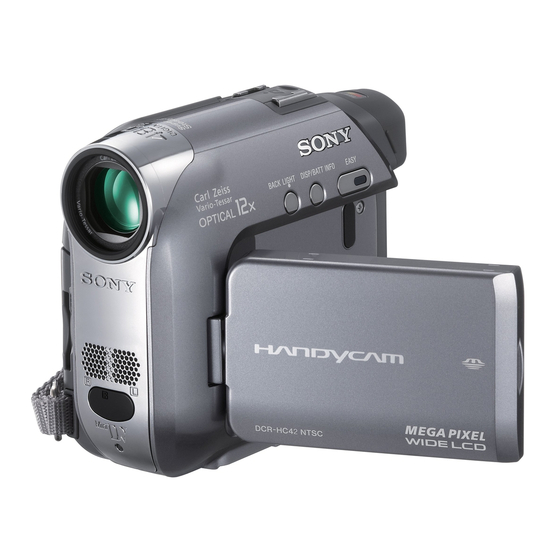
Photo: DCR-HC43E
BLOCK DIAGRAMS
BLOCK DIAGRAMS
FRAME SCHEMATIC DIAGRAMS
FRAME SCHEMATIC DIAGRAMS
SCHEMATIC DIAGRAMS
SCHEMATIC DIAGRAMS
The following pages are not shown.
Schematic diagrams ..................... Pages 4-9 to 4-46
Printed wiring boards .................... Pages 4-67 to 4-70
Waveforms ..................................... Pages 4-82 to 4-87
Mounted parts location .................. Pages 4-90 and 4-91
Electrical parts list ......................... Pages 5-15 to 5-22
DIGITAL VIDEO CAMERA RECORDER
Sony EMCS Co.
RMT-831
DCR-HC42
DCR-HC39E/HC42E
East European Model
North European Model
DCR-HC42/HC42E/HC43E
DCR-HC42E
DCR-HC43
DCR-HC43E
DCR-HC42/HC42E
DCR-HC42
DCR-HC41
PRINTED WIRING BOARDS
PRINTED WIRING BOARDS
REPAIR PARTS LIST
REPAIR PARTS LIST
VIII
Published by DI Technical Support Section
US Model
Canadian Model
AEP Model
UK Model
E Model
Australian Model
Hong Kong Model
Brazilian Model
Chinese Model
Tourist Model
Korea Model
Japanese Model
2005A0500-1
© 2005.1
Advertisement
Chapters
Table of Contents

Related Manuals for Sony DCR-HC39E


Summary of Contents for Sony DCR-HC39E
- Page 1 VC-378 board are Mounted parts location ....Pages 4-90 and 4-91 not shown. Electrical parts list ......Pages 5-15 to 5-22 DIGITAL VIDEO CAMERA RECORDER 2005A0500-1 DCR-HC39E/HC41/HC42/HC42E/HC43/HC43E © 2005.1 Sony EMCS Co. 9-876-783-31 Published by DI Technical Support Section...
-
Page 2: Specifications
(using a DVM60 cassette) DCRA-C123 (DCR-HC39E) Viewfinder Electric viewfinder LANC jack Stereo mini-minijack (Ø 2.5 mm) Audio/Video 10-pin connector DCR-HC39E: black and white Video signal: 1 Vp-p, 75 Ω (ohms), output DCR-HC42/HC42E/HC43/HC43E: LCD screen unbalanced color Luminance signal: 1 Vp-p, 75 Ω... - Page 3 ENGLISH JAPANESE ENGLISH JAPANESE DCR-HC39E/HC41/HC42/HC42E/HC43/HC43E — 3 —...
- Page 4 Table for differences of function Model DCR-HC39E DCR-HC41 DCR-HC42 DCR-HC42E US, CND, E, KR, AEP, UK, NE, EE, Destination AEP, UK, NE, EE E, AUS, HK, JE Color system NTSC NTSC Electrical viewfinder Black and White Color Color Color Digital zoom...
- Page 5 CRITIQUES POUR LA SÉCURITÉ DE FONCTIONNEMENT. NE COMPONENTS WITH SONY PARTS WHOSE PART NUMBERS REMPLACER CES COMPOSANTS QUE PAR DES PIÈSES SONY APPEAR AS SHOWN IN THIS MANUAL OR IN SUPPLEMENTS DONT LES NUMÉROS SONT DONNÉS DANS CE MANUEL OU PUBLISHED BY SONY.
- Page 6 ENGLISH JAPANESE ENGLISH JAPANESE DCR-HC39E/HC41/HC42/HC42E/HC43/HC43E — 6 —...
-
Page 7: Table Of Contents
CR-050 ·········································································· 4-73 SI-042 ············································································ 4-74 LB-109 ··········································································· 4-74 JK-278 ··········································································· 4-75 MS-249 ·········································································· 4-76 FP-180, FP-186, FP-187 FLEXIBLE ···························· 4-77 FP-826, FP-467, FP-228 FLEXIBLE ···························· 4-79 4-4. Waveforms ····································································· 4-81 4-5. Mounted Parts Location ················································ 4-89 DCR-HC39E/HC41/HC42/HC42E/HC43/HC43E — 7 —... -
Page 8: Service Note
In this unit, about 10 seconds after power is supplied to the battery terminal using the regulated power supply (8.4V), the power is shut off so that the unit cannot operate. These following method is available to prevent this. Method: Use the AC power adaptor (AC-L25A/L25B). DCR-HC39E/HC41/HC42/HC42E/HC43/HC43E... -
Page 9: To Take Out A Cassette When Not Eject (Force Eject)
C : Corrected by customer Indicates the appropriate Refer to “1-4-3. Self-diagnosis Code Table”. H : Corrected by dealer step to be taken. E : Corrected by service E.g. engineer 31 ..Reload the tape. 32 ..Turn on power again. DCR-HC39E/HC41/HC42/HC42E/HC43/HC43E... -
Page 10: Self-Diagnosis Code Table
PG fault during normal drum Remove the battery or power cable, connect, and perform operations. operations from the beginning. Phase fault during normal drum Remove the battery or power cable, connect, and perform operations. operations from the beginning. DCR-HC39E/HC41/HC42/HC42E/HC43/HC43E... - Page 11 Inspect pitch angular velocity sensor (SE601 of SI-042 board) (With pitch angular velocity sensor output peripheral circuits. stopped.) Steadyshot function does not work well. Inspect yaw angular velocity sensor (SE602 of SI-042 board) (With yaw angular velocity sensor output peripheral circuits. stopped.) DCR-HC39E/HC41/HC42/HC42E/HC43/HC43E...
- Page 12 ENGLISH JAPANESE ENGLISH JAPANESE 1. SERVICE NOTE DCR-HC39E/HC41/HC42/HC42E/HC43/HC43E...
- Page 13 ENGLISH JAPANESE ENGLISH JAPANESE DCR-HC39E/HC41/HC42/HC42E/HC43/HC43E...
- Page 14 ENGLISH JAPANESE ENGLISH JAPANESE DCR-HC39E/HC41/HC42/HC42E/HC43/HC43E...
- Page 15 ENGLISH JAPANESE ENGLISH JAPANESE DCR-HC39E/HC41/HC42/HC42E/HC43/HC43E 1-8E...
-
Page 16: Disassembly
5 Tapping screw x2 qd Flexible board: CN605 6 P2 tapping screw x2 qf Tape (W) x1 7 Claw x6 qg Flexible board: CN603 8 P cabinet (C (106)) qh P2 tapping screw x1 9 FP-185 flexible board: CN601 qj PD-238 board DCR-HC39E/HC41/HC42/HC42E/HC43/HC43E... - Page 17 6 P2 lock ace screw (M1.7) x2 7 VC-378 board 7 CS block 1 P2 tapping screw x3 2 P2 lock ace screw (M1.7) x1 3 Control key block (SS10300) 4 P2 lock ace screw (M1.7) x2 5 CS frame block 6 JK-278 board DCR-HC39E/HC41/HC42/HC42E/HC43/HC43E...
-
Page 18: Mechanism Deck Service Position
*: To eject a cassette, connect the cabinet (L) block assembly. Control key block (SS10300) Lens block Adjustment remote commander (RM95) Mechanism deck I/F unit for LANC control (J-6082-521-A) VC-378 board Color monitor LANC jack CPC-15 (J-6082-564-A) JK-278 board AC adaptor AC IN A/V jack BT panel block DCR-HC39E/HC41/HC42/HC42E/HC43/HC43E... -
Page 19: Lcd Service Position
(103) assembly in the direction of arrow Hinge (103) assembly Adjustment remote commander (RM95) Hinge cover (M) Lcd panel I/F unit for LANC control (J-6082-521-A) FP-185 flexible board PD-238 board CPC-15 (J-6082-564-A) Lighit guide plate block AC adaptor AC IN DCR-HC39E/HC41/HC42/HC42E/HC43/HC43E... -
Page 20: Circuit Boards Location
A/D CONVERTER, TIMING GENERATOR, LENS DRIVE, CAMERA SIGNAL PROCESS, VIDEO/AUDIO DSP, DS/HI CONTROL, FLASH, SDRAM, DV SIGNAL PROCESS, DV INTERFACE, REC/PB AMP, ASPECT RATIO CONVERTER, VIDEO, AUDIO I/O, MIC AMP, EVF DRIVE, CAMERA/MECHA CONTROL, SERVO, HI CONTROL, DC IN, DC/DC CONVERTER, CONNECTOR DCR-HC39E/HC41/HC42/HC42E/HC43/HC43E 2-10E... - Page 21 HELP Sheet attachment positions and procedures of processing the flexible boards/harnesses are shown. Tape (A) FP-181 flexible board FP-180 flexible board Tape (A) VC-376/VC-377 board BT panel assy Tape (BT) FP-180 flexible board DCR-HC39E/HC41/HC42/HC42E/HC43/HC43E HELP...
-
Page 22: Block Diagrams
OVERALL BLOCK DIAGRAM (3/6) POWER BLOCK DIAGRAM (2/3) OVERALL BLOCK DIAGRAM (3/6) POWER BLOCK DIAGRAM (2/3) OVERALL BLOCK DIAGRAM (4/6) POWER BLOCK DIAGRAM (3/3) OVERALL BLOCK DIAGRAM (4/6) POWER BLOCK DIAGRAM (3/3) OVERALL BLOCK DIAGRAM (5/6) OVERALL BLOCK DIAGRAM (5/6) DCR-HC39E/HC41/HC42/HC42E/HC43/HC43E... - Page 23 PITCH SENSOR IC602 XRST VTR OVERALL (4/6) PITCH/YAW SE602 SPCK (PAGE 3-7) SENSOR YAW AD YAW AD YAW SENSOR CAM DD ON VST C RESET VST C RESET OVERALL (4/6) XSHUTTER OPEN (PAGE 3-7) IR ON : VIDEO SIGNAL DCR-HC39E/HC41/HC42/HC42E/HC43/HC43E...
- Page 24 48 50 51 53 (PAGE 3-9) XCS SDRAM VM IC5201 IC5202 16M SDRAM : VIDEO SIGNAL 32M FLASH (6/19) LINEOUT V (6/19) : AUDIO SIGNAL OVERALL (6/6) XSYS RST XCS FLASH : VIDEO/AUDIO SIGNAL (PAGE 3-11) : VIDEO/AUDIO/SERVO SIGNAL DCR-HC39E/HC41/HC42/HC42E/HC43/HC43E...
- Page 25 VFI OE OVERALL (2/6) ALIGN VD MIC902 (PAGE 3-3) LINEOUT V REC PROOF REC PROOF VREF CHIME SDA, CHIME SCK 4PIN CONNECTOR S903 CC DOWN XCC DOWN XCC DOWN OVERALL (6/6) (PAGE 3-11) : VIDEO/AUDIO/SERVO SIGNAL : SERVO SIGNAL DCR-HC39E/HC41/HC42/HC42E/HC43/HC43E...
- Page 26 1 – 3 BL REG CAM DD ON 64k EEPROM 103 – 105 (5/19) OVERALL (1/6) XSHUTTER OPEN (PAGE 3-2) IR ON : VIDEO SIGNAL Q5103, 5104 BEEP MELODY MODULATOR OVERALL (5/6) MELODY ENV (PAGE 3-9) ZOOM MIC CONT SHOE STEREO DCR-HC39E/HC41/HC42/HC42E/HC43/HC43E...
- Page 27 (1/2) TPA, NTPA, TPB, NTPB TPA, NTPA, TPB, NTPB MULTI JACK IN : VIDEO SIGNAL OVERALL (6/6) MULTI JACK IN CRADLE (PAGE 3-11) : AUDIO SIGNAL USB D± USB D± D1016 : VIDEO/AUDIO SIGNAL USB DET USB DET DCR-HC39E/HC41/HC42/HC42E/HC43/HC43E 3-10...
- Page 28 EP 8.5V XCC DOWN (PAGE 3-5) IC 6001 13.5V BL REG CAM 15V MULTI JACK IN OVERALL (5/6) CAM -7.5V MULTI JACK IN CRADLE (PAGE 3-9) EVER 3.0V VOUT CAM DD ON OVERALL (4/6) LANC DC (PAGE 3-7) DCR-HC39E/HC41/HC42/HC42E/HC43/HC43E 3-11 3-12...
-
Page 29: Power Block Diagram (1/3)
HI EVER SCK CAM DD ON BATT IN BATT IN OUTC1 VTR DD ON VTR DD ON CTL1 XCS DD XCS DD XLANC PWR ON XLANC POWER ON WAKEUP XLANC ON XLANC ON XCTL2 MT 5V MT 5V DCR-HC39E/HC41/HC42/HC42E/HC43/HC43E 3-13 3-14... -
Page 30: Power Block Diagram (2/3)
EP 4.6V L7001 EP 2.8V EP 2.8V D 2.8V D303 A 4.6V IC7001 (BACKLIGHT) FB7001 A 2.8V EVF DRIVE EP 8.5V (13/19) EP 4.6V POWER (3/3) EP 2.8V (PAGE 3-17) NS 2.8V NS 2.8V BL REG BL REG DCR-HC39E/HC41/HC42/HC42E/HC43/HC43E 3-15 3-16... -
Page 31: Power Block Diagram (3/3)
COLOR L601 EP 2.8V EP 2.8V LCD UNIT LCD DRIVE FB601 CN608 NS 2.8V NS 2.8V BL 2.8V BL REG BL REG BL L Q606, 607, 611, 613 BACKLIGHT BL H DRIVE IC601 D901 BACKLIGHT BACKLIGHT CONTROL DCR-HC39E/HC41/HC42/HC42E/HC43/HC43E 3-17 3-18E... -
Page 32: Printed Wiring Boards And Schematic Diagrams
WIDE COLOR LCD UNIT XEJECT_SW HOTSHOE_ID1 PANEL BACKLIGHT REG_GND SHOE_UNREG ZOOM_VR SHOE_UNREG CONTROL D_2.8V SHOE_UNREG HOT SHOE KEY_AD2(PHOTO) SHOE_UNREG REG_GND SHOE_UNREG LCD901 XPOWER_SW HOTSHOE_ID2 XMODE_SW EXT_STROBO BLOCK XVTR_LED LANC_SIG XMEM_LED SHOE_CONT (SS10300) MODE_LED_VDD SHOE_UNREG_GND XCAM_LED SHOE_UNREG_GND REG_GND SHOE_UNREG_GND KEY_AD0(SS) SHOE_UNREG_GND DCR-HC39E/HC41/HC42/HC42E/HC43/HC43E FRAME... -
Page 33: Schematic Diagrams
JK-278 BOARD (JACK) CONTROL KEY BLOCK JK-278 BOARD (JACK) (SS10300) (SS10300) MS-249 BOARD CONTROL KEY BLOCK MS-249 BOARD (MS CONNECTOR) CONTROL KEY BLOCK (MS CONNECTOR) (SB10600) (SB10600) COMMON NOTE FOR SCHEMATIC DIAGRAMS WAVEFORMS COMMON NOTE FOR SCHEMATIC DIAGRAMS WAVEFORMS DCR-HC39E/HC41/HC42/HC42E/HC43/HC43E... - Page 34 0 are critical for safety. dusts nor exposed to strong light. Replace only with part number specified. Les composants identifiés par une marque 0 sont critiques pour la sécurité. Ne les remplacer que par une pièce portant le numéro spécifie. DCR-HC39E/HC41/HC42/HC42E/HC43/HC43E...
- Page 35 ENGLISH JAPANESE 4-2. SCHEMATIC DIAGRAMS ENGLISH JAPANESE 4-2. SCHEMATIC DIAGRAMS (JAPANESE) DCR-HC39E/HC41/HC42/HC42E/HC43/HC43E...
- Page 36 C204 0.1u 0.1u R203 C212 R213 IDRV R214 R205 IC202 C216 C213 R206 C221 100p C220 100p C214 0.1u C210 C215 C211 R202 4.7u L201 100uH R201 VC-378 (1/19) CN3201 THROUGH THE FP-179 FLEXIBLE PAGE 4-9 of LEVEL3 DCR-HC39E/HC41/HC42/HC42E/HC43/HC43E CD-534...
- Page 37 Schematic diagrams of the VC-378 board are not shown. Pages from 4-9 to 4-46 are not shown. DCR-HC39E/HC41/HC42/HC42E/HC43/HC43E...
- Page 38 A_OUT R643 2200 Q601 Q606 Q611 XP4216-TXE A_IN- B_OUT 2SA1576A-T106-QR 2SA1576A-T106-QR Q607 A_IN+ B_IN- C633 2SA1576A-T106-QR R606 4.7u B_IN+ 220k ±0.5% Q606,607,611 BACKLIGHT DRIVE C602 R639 2200p R603 R638 LND601 Q613 EMX1T2R CH_GND BACKLIGHT DRIVE R604 DCR-HC39E/HC41/HC42/HC42E/HC43/HC43E PD-238 4-47 4-48...
-
Page 39: Cradle Terminal
ACV_GND of LEVEL3 ACV_GND D007 EDZ TE61 6.8B ACV_GND ACV_GND ACV_GND ACV_GND ACV_GND ACV_GND ACV_GND N.C. N.C. N.C. N.C. TO CRADLE UNIT ACV_UNREG ACV_UNREG ACV_UNREG ACV_UNREG ACV_UNREG ACV_UNREG ACV_UNREG ACV_UNREG ACV_UNREG ACV_UNREG D001 MAZB068H0LS0 D002 MAZB068H0LS0 DCR-HC39E/HC41/HC42/HC42E/HC43/HC43E CR-050 4-49 4-50... -
Page 40: Pitch/Yaw Sensor
IC602 NJM3230V(TE2) FB603 11 12 13 14 15 16 17 18 19 20 C608 FB604 0.047u C621 0.1u 6.3V C610 Vref 0.047u SE602 YAW SENSOR C613 R602 6.3V C620 C614 R603 6.3V C619 4.7u LND603 REG_GND DCR-HC39E/HC41/HC42/HC42E/HC43/HC43E SI-042 4-51 4-52... -
Page 41: Flexible
Les composants identifiés par une marque 0 sont line with mark 0 are critical for safety. critiques pour la sécurité. Ne les remplacer que Replace only with part number specified. par une piéce portant le numéro spécifié. DCR-HC39E/HC41/HC42/HC42E/HC43/HC43E FP-182, JK-278, MS-249 4-53 4-54... -
Page 42: Evf, Evf Backlight
(PANEL REVERSE) PANEL_REVERSE S001 PAGE 4-47 LND006 REG_GND of LEVEL2 DSPL/ LND105 N.C. LND007 XCHARGE_LED BATT INFO LND106 REG_GND LND008 CHARGE_LED_VDD S002 EASY R003 D001 CL-197HB1-D-T (EASY) D002 D003 VMZ6.8NT2L VMZ6.8NT2L D004 R004 SML-311YTT86 DCR-HC39E/HC41/HC42/HC42E/HC43/HC43E LB-109, FP-180, FP-186, FP-187 4-55 4-56... -
Page 43: Flexible (Panel Reverse Detect)
S REEL Q901 SENSOR TAPE END Q902 SENSOR TAPE TOP SENSOR FP-228 D901 (TAPE LED) S903 H902 FLEXIBLE (CC DOWN) T REEL SENSOR SENSOR BOARD FP-826 4 PIN MIC902 FLEXIBLE CONNECTOR BOARD (REC PROOF) DCR-HC39E/HC41/HC42/HC42E/HC43/HC43E FP-826, FP-467, FP-228 4-57 4-58... -
Page 44: Control Key Block (Ss10300)
LND004 2ND_S/S_SW LND005 XCAM_LED LND003 REG_GND LND006 REG_GND LND002 S001 KEY_AD0(SS) LND001 START/STOP S002 R001 D003 (PHOTO REC) PLAY/EDIT R002 D002 PHOTO 2700 CAMERA-MEMORY S003 (PHOTO FREEZE) D001 CAMERA-TAPE POWER XPOWER_SW MODE XMODE_SW S004 START/STOP DCR-HC39E/HC41/HC42/HC42E/HC43/HC43E SS10300, SB10600 4-59 4-60... -
Page 45: Printed Wiring Boards
Board Name Function CD-534 CCD IMAGER PD-238 LCD DRIVE, BACKLIGHT DRIVE CR-050 CRADLE TERMINAL SI-042 REMOTE COMMANDER RECEIVER, PITCH/YAW SENSOR LB-109 EVF, EVF BACKLIGHT JK-278 JACK MS-249 MS CONNECTOR FP-180 DC IN FP-186 PANEL REVERSE DETECT FP-187 CONTROL SWITCH DCR-HC39E/HC41/HC42/HC42E/HC43/HC43E... -
Page 46: Flexible
1 layer – FP-186 Flexible – – 1 layer – FP-187 Flexible – – 1 layer – FP-826 Flexible – – 1 layer – FP-467 Flexible – – 1 layer – FP-228 Flexible – – 1 layer – DCR-HC39E/HC41/HC42/HC42E/HC43/HC43E 4-63... - Page 47 CD-534 BOARD (SIDE B) C215 C211 C220 C214 C213 R210 Q201 Q202 E C B C212 IC201 C207 C205 C208 C209 R205 R203 CN201 R215 C202 C204 C201 1-864-373- 1-864-373- Note: IC201 is not included in CD-534 complete board. DCR-HC39E/HC41/HC42/HC42E/HC43/HC43E CD-534 4-65 4-66...
- Page 48 Printed wiring boards of the VC-378 board are not shown. Pages from 4-67 to 4-70 are not shown. DCR-HC39E/HC41/HC42/HC42E/HC43/HC43E...
- Page 49 C601 C627 R610 D601 Q602 IC601 R643 Q601 R607 C607 R616 D604 R636 Q613 C613 R625 C625 R617 R619 FB601 R623 R628 R615 IC602 R609 R605 C610 R613 R620 C611 R614 C623 C609 L601 CN601 1-864-380- DCR-HC39E/HC41/HC42/HC42E/HC43/HC43E PD-238 4-71 4-72...
- Page 50 LND601 C613 CAMERA 1-864-376- 11 RECORDING 1-864-376- LB-109 : Uses unleaded solder. LB-109 BOARD (SIDE A) LB-109 BOARD (SIDE B) D006 D302 R304 CN302 D007 R303 C302 R302 1-864-368- D303 CN301 (BACKLIGHT) 1-864-374- 1-864-374- DCR-HC39E/HC41/HC42/HC42E/HC43/HC43E CR-050, SI-042, LB-109 4-73 4-74...
- Page 51 CN701 D705 EXCEPT HC39E D707 CN701 FB701 J701 J701 LANC 1-864-377- 1-864-377- BT501 1-864-375- BT501 BATTERY, CAUTION LITHIUM SECONDARY Danger of explosion if battery is incorrectly replaced. Replace only with the same or equivalent type. DCR-HC39E/HC41/HC42/HC42E/HC43/HC43E JK-278, MS-249 4-75 4-76...
- Page 52 S002, D001 D004 BACK LIGHT DISP/BATT INFO EASY D002 D001 S003 S001 S002 R001 FP-187 R003 D004 R002 : Uses unleaded solder. FP-187 FLEXIBLE BOARD S004 PANEL CLOSE/OPEN > < S004 FP-1871-864-763- 1-864-763- 11 DCR-HC39E/HC41/HC42/HC42E/HC43/HC43E FP-180, FP-186, FP-187 4-77 4-78...
- Page 53 (CC DOWN) S REEL SENSOR SENSOR Q901 TAPE END SENSOR (REC PROOF) 1-861-117- 4 PIN CONNECTOR D901 (TAPE LED) MIC902 S902 MODE SWITCH M902 LOADING MOTOR FP-228 FLEXIBLE BOARD SENSOR 1-677-049- FP-467 FLEXIBLE BOARD 1-686-798- DCR-HC39E/HC41/HC42/HC42E/HC43/HC43E FP-826, FP-467, FP-228 4-79 4-80...
-
Page 54: Waveforms
CD-534 BOARD CD-534 BOARD 4-4. WAVEFORMS CD-534 BOARD 200 mVp-p IC203 qa REC 350 mVp-p IC203 5 REC DCR-HC39E/HC41/HC42/HC42E/HC43/HC43E CD-534 4-81... - Page 55 Waveforms of the VC-378 board are not shown. Pages 4-82 to 4-87 are not shown. DCR-HC39E/HC41/HC42/HC42E/HC43/HC43E...
- Page 56 IC602 wa REC/PB 470 mVp-p 3.1 Vp-p IC602 ed REC/PB IC602 w; REC/PB 460 mVp-p 2.8 Vp-p IC602 es REC/PB IC602 1 REC/PB 4.1 Vp-p 2.8 Vp-p IC602 rk REC/PB IC602 wh REC/PB 3.1 Vp-p IC602 ws REC/PB DCR-HC39E/HC41/HC42/HC42E/HC43/HC43E PD-238 4-88...
-
Page 57: Mounted Parts Location
* C217 * C218 * C219 * C220 * C221 * CN201 B-1 * FB201 * IC203 * L201 * L202 * Q201 * Q202 * R203 * R207 * R210 * R211 * R212 * R215 DCR-HC39E/HC41/HC42/HC42E/HC43/HC43E CD-534 4-89... - Page 58 Mounted parts location of the VC-378 board are not shown. Pages 4-90 and 4-91 are not shown. DCR-HC39E/HC41/HC42/HC42E/HC43/HC43E...
- Page 59 * SE601 Q609 * SE602 Q610 Q611 Q613 R605 R606 R608 R609 R613 R614 R615 R616 R617 R619 R620 R623 R624 R625 R626 R627 R628 R634 R636 R637 R638 R639 R642 R643 R644 R645 RB601 B-2 DCR-HC39E/HC41/HC42/HC42E/HC43/HC43E PD-238, SI-042, JK-278 4-92E...
-
Page 60: Repair Parts List
MS-249 BOARD CR-050 BOARD FP-467 FLEXIBLE BOARD MS-249 BOARD FP-180 FLEXIBLE BOARD FP-826 FLEXIBLE BOARD PD-238 BOARD FP-180 FLEXIBLE BOARD FP-826 FLEXIBLE BOARD PD-238 BOARD FP-186 FLEXIBLE BOARD JK-278 BOARD SI-042 BOARD FP-186 FLEXIBLE BOARD JK-278 BOARD SI-042 BOARD DCR-HC39E/HC41/HC42/HC42E/HC43/HC43E... - Page 61 (JAPANESE) • Abbreviation AUS : Australian model : Brazilian model : Chinese model CND : Canadian model : East European model HK : Hong Kong model : Japanese model : Tourist model : Korea model : North European model DCR-HC39E/HC41/HC42/HC42E/HC43/HC43E...
- Page 62 2-188-484-01 COVER (106), SHOE 3-089-520-01 SCREW 3-080-198-31 SCREW (M1.7), LOCK ACE, P2 2-188-478-01 LID, CPC A-1101-191-A VC-378 BOARD, COMPLETE (SERVICE) 3-062-214-01 SCREW (M1.4X1.5) (HC39E) 3-081-221-01 LABEL (Z), LS A-1101-199-A VC-378 BOARD, COMPLETE (SERVICE) 1-829-774-11 CABLE, FLEXIBLE FLAT (FFC-038) (HC41/HC42/HC43) 3-089-544-01 LABEL, VF DCR-HC39E/HC41/HC42/HC42E/HC43/HC43E...
- Page 63 Part No. Description Ref. No. Part No. Description X-2024-832-1 PANEL ASSY (480), FRONT (EXCEPT HC41) A-1081-844-A SI-042 BOARD, COMPLETE X-2024-833-1 PANEL ASSY (150), FRONT (HC41) CAUTION TAPE (A) 3-089-771-01 CUSHION, MICROPHONE 2-188-425-01 RETAINER, IR 3-078-890-11 SCREW, TAPPING MIC901 1-542-513-21 MICROPHONE DCR-HC39E/HC41/HC42/HC42E/HC43/HC43E...
-
Page 64: Lens Block
3-088-645-01 RUBBER (Z), SEAL 3-080-204-01 SCREW, TAPPING, P2 2-349-848-01 SHEET (CD), RADIATION 1-788-241-11 OPTICAL FILTER BLOCK 2-594-270-01 SHEET (G), CD COPPER LEAF 3-080-204-21 SCREW, TAPPING, P2 IC201 A-1103-137-A CCD BLOCK ASSY (CCD IMAGER) (Note1, 2) A-1081-699-A CD-534 BOARD, COMPLETE DCR-HC39E/HC41/HC42/HC42E/HC43/HC43E... -
Page 65: Cabinet (R) Block
X-2024-696-1 CABINET R ASSY (HC41) 2-593-937-01 FOOT (RR), RUBBER A-1082-042-A FP-186 FLEXIBLE BOARD 3-089-565-01 CUSHION (R), PANEL 1-478-984-11 KEY BLOCK, CONTROL (SB10600) D901 1-478-990-11 BLOCK, LIGHT GUIDE PLATE (2.7) 2-188-437-01 CUSHION (106), PANEL LCD901 A-1083-763-A TP BLOCK ASSY 27STGU DCR-HC39E/HC41/HC42/HC42E/HC43/HC43E... -
Page 66: Cs Block
1-478-982-71 KEY BLOCK, CONTROL (SS10300) (HC41) 2-188-514-01 FOOT (G), RUBBER 3-080-204-01 SCREW, TAPPING, P2 2-583-616-01 BELT (FRONT), GRIP A-1081-841-A JK-278 BOARD, COMPLETE 0 BT501 1-756-075-21 BATTERY, LITHIUM (SECONDARY) 3-959-978-02 CUSHION, PANEL SP901 1-825-260-23 LOUD SPEAKER (1.6cm) X-2023-773-1 FRAME ASSY, CS DCR-HC39E/HC41/HC42/HC42E/HC43/HC43E... -
Page 67: Bat Evf Block
3-089-416-01 SHEET, PRISM J001 1-815-792-11 CONNECTOR, DC-IN (7.2V) (DC IN) 3-089-419-01 CUSHION, LCD LCD902 8-753-208-78 LCX059AKA-J 3-080-204-21 SCREW, TAPPING, P2 (HC41/HC42/HC42E/HC43/HC43E: E) X-2023-648-1 EYE CUP ASSY LCD902 8-753-208-84 LCX059ALA-1 (HC39E) LCD902 8-753-234-59 LCX059ZKA-1 (HC43E: CH) X-2023-647-1 CABINET UPPER ASSY VF DCR-HC39E/HC41/HC42/HC42E/HC43/HC43E... -
Page 68: Mechanism Deck
A-1082-424-A MD (Z210) SUB ASSY 3-079-367-01 DAMPER, CASSETTE COMPARTMENT 3-079-741-02 SCREW, DRUM FIXING 3-079-215-02 SPRING (POP UP T), EXTENSION 3-748-682-01 WASHER, T 3-085-330-01 SCREW, SPECIAL 3-087-881-01 SHEET, ADHESIVE, FLEXIBLE 3-080-545-01 COVER, SENSOR S M901 A-7048-994-A DRUM (DEH-30B-R) (SERVICE) 3-079-364-01 RETAINER, LS GUIDE DCR-HC39E/HC41/HC42/HC42E/HC43/HC43E... -
Page 69: Ls Chassis Block Assembly
MIC902 1-817-175-12 PIN, CONNECTOR (WITH DETECTION SWITCH) 3-079-267-01 HOLDER (S), SENSOR Q901 6-550-672-01 TRANSISTOR PT4850FJE00F (TAPE END) 3-079-268-01 HOLDER (T), SENSOR Q902 6-550-672-01 TRANSISTOR PT4850FJE00F (TAPE TOP) X-3952-936-2 TABLE ASSY, S REEL S903 1-529-566-51 SWITCH, PUSH (1 KEY) (C.C. DOWN) 3-085-330-01 SCREW, SPECIAL DCR-HC39E/HC41/HC42/HC42E/HC43/HC43E... -
Page 70: Mechanism Chassis Block Assembly
X-3952-927-2 COASTER (S) ASSY X-3954-273-2 PLATE ASSY (N), TG2 CAM X-3952-930-3 ROLLER ASSY, TG5 3-079-312-01 SHIELD, MOTOR X-3952-929-1 COASTER (T) ASSY 3-079-307-02 HOLDER, MOTOR M902 A-7095-396-A MOTOR BLOCK ASSY, L (LOARDING) 3-085-330-01 SCREW, SPECIAL S902 1-477-679-11 ROTARY, ENCODER (SWITCH) (MODE SWITCH) DCR-HC39E/HC41/HC42/HC42E/HC43/HC43E 5-10... -
Page 71: Electrical Parts List
A-1081-704-A CR-050 BOARD, COMPLETE *********************** < CONNECTOR > CN001 1-817-283-41 CONNECTOR, FPC (ZIF) 51P CN002 (Not supplied) CONNECTOR, MULTIPLE (SOCKET) Note: Be sure to read “Precautions for Replacement of CCD Imager” on page 4-5 when changing the CCD imager. DCR-HC39E/HC41/HC42/HC42E/HC43/HC43E 5-11... - Page 72 Les composants identifiés par une mark 0 or dotted line with marque 0 sont critiques pour la mark 0 are critical for safety. sécurité. Replace only with part num- Ne les remplacer que par une pièce ber specified. portant le numéro spécifié. DCR-HC39E/HC41/HC42/HC42E/HC43/HC43E 5-12...
- Page 73 8-729-026-53 TRANSISTOR 2SA1576A-T106-QR < CONNECTOR > Q607 8-729-026-53 TRANSISTOR 2SA1576A-T106-QR Q608 6-550-234-01 TRANSISTOR UNR32A300LS0 CN601 1-778-507-21 PIN, CONNECTOR (PC BOARD) 4P CN603 1-766-348-21 CONNECTOR, FFC/FPC 18P Q609 8-729-041-23 TRANSISTOR NDS356AP Q610 6-550-232-01 TRANSISTOR 2SA2029T2LQ/R Q611 8-729-026-53 TRANSISTOR 2SA1576A-T106-QR DCR-HC39E/HC41/HC42/HC42E/HC43/HC43E 5-13...
- Page 74 1-786-148-11 SWITCH, PUSH (1 KEY) (LENS COVER OPEN) < SENSOR > SE601 1-476-807-41 SENSOR, ANGULAR VELOCITY (PITCH SENSOR) SE602 1-476-807-31 SENSOR, ANGULAR VELOCITY (YAW SENSOR) Electrical parts list of the VC-378 board is not shown. Pages 5-15 to 5-22 are not shown. DCR-HC39E/HC41/HC42/HC42E/HC43/HC43E 5-14...
- Page 75 Les composants identifiés par une mark 0 or dotted line with marque 0 sont critiques pour la mark 0 are critical for safety. sécurité. DCR-HC39E/HC41/HC42/HC42E/HC43/HC43E Replace only with part num- Ne les remplacer que par une pièce ber specified. portant le numéro spécifié.
- Page 76 • J MODEL DCR-HC39E/HC41/HC42/HC42E/HC43/HC43E 5-24E...
- Page 77 ENGLISH JAPANESE ENGLISH JAPANESE [Description of main button functions on toolbar of the Adobe Acrobat Reader Ver5.0 (for Windows)] Toolbar Printing a text Reversing the screens displayed once • To reverse the previous screens (operation) one by one, click 1. Click the Print button 2.
- Page 78 ENGLISH JAPANESE ENGLISH JAPANESE...
-
Page 79: Revision History
Reverse 987678331.pdf Revision History S.M. Rev. Ver. Date History Contents issued 2005.01 Official Release — — DCR-HC39E/HC41/HC42/HC42E/HC43/HC43E... - Page 80 VIDEO SYSTEM ADJUSTMENTS INITIALIZATION OF 8, A, B, C, D, E, F, 14, 18, INITIALIZATION OF 8, A, B, C, D, E, F, 14, 18, AUDIO SYSTEM ADJUSTMENTS (DCR-HC39E) AUDIO SYSTEM ADJUSTMENTS (DCR-HC39E) 19, 1A, 1B, 1C, 1E, 1F PAGE DATA...
- Page 81 Overall Noise Level Check ············································ 6-56 Flange Back Check ························································ 6-27 Overall Separation Check ·············································· 6-56 Picture Frame Setting 3-6. Audio System Adjustments (Except DCR-HC39E) ······ 6-57 (Color reproduction adjustment frame) ························· 6-28 Playback Level Check ··················································· 6-57 Picture Frame Setting (Center frame) ··························· 6-29 Overall Level Characteristics Check ·····························...
- Page 82 Record of Use Check (1) ··············································· 6-66 Record of Use Check (2) ··············································· 6-67 Record of Use Check (3) ··············································· 6-68 Record of Self-diagnosis Check ···································· 6-68 * The color reproduction frame is shown on page 6-69 DCR-HC39E/HC41/HC42/HC42E/HC43/HC43E — 3 —...
-
Page 83: Adjustments
Download the data. Save the data. (The same model of the same destination) After the EVR data is saved and downloaded, check the respective items of the EVR data. (Refer to page 6-3 for the items to be checked) DCR-HC39E/HC41/HC42/HC42E/HC43/HC43E... -
Page 84: Adjusting Items When Replacing Main Parts And 2. Boards
Note 1: When replacing the drum assy or the mechanism deck, reset the data of page: 7, address: A8 to AB to “00”. (Refer to “Record of Use check” of “6-4. SERVICE MODE”) Note 2: Except DCR-HC39E model only. Replaced part... - Page 85 Switching position adj. Error rate check Video S VIDEO OUT Y level adj (1). S VIDEO OUT chroma level adj (1). S VIDEO OUT Y level adj (2). S VIDEO OUT chroma level adj (2). IC4701 automatic adj. Table 6-1-1 (2) DCR-HC39E/HC41/HC42/HC42E/HC43/HC43E...
-
Page 86: Camera Section Adjustments
Filter for color ND filter 0.4 Siemens star chart temperature correction J-6080-806-A J-6080-875-A (C14) ND filter 0.1 J-6080-058-A J-6080-807-A J-10 J-11 J-12 A: CPC-15 J-6082-564-A Back ground paper Camera table B: I/F unit for J-2501-130-A J-6082-384-A LANC control J-6082-521-A Fig. 6-1-1 DCR-HC39E/HC41/HC42/HC42E/HC43/HC43E... -
Page 87: Preparations
1) Connect the equipment for adjustments according to Fig. 6-1-3. Front of the lens L=1m (PTB-450) L=40cm (PTB-1450) Fig. 6-1-2 LANC jack A/V jack (Except DCR-HC39E) A/V OUT jack (DCR-HC39E) Adjustment remote commander (RM-95) S Video (Black) Color monitor Vectorscope... -
Page 88: Precaution
Fig. 6-1-5. 1189 mm Note: Use a non-reflecting and non-glazing vellum paper. The size must be A0 or larger and the joint between the white Fig. 6-1-5 and black paper must not have any undulations. DCR-HC39E/HC41/HC42/HC42E/HC43/HC43E... -
Page 89: Preparing The Flash Adjustment Box
4) Assemble so that the black sides and the background paper side of woody board A, B and C are internal. (Fig. 6-1-7) woody board A woody board B woody board A woody board B woody board C Fig. 6-1-7 DCR-HC39E/HC41/HC42/HC42E/HC43/HC43E... -
Page 90: Initialization Of 8, A, B, C, D, E, F
26: Initializing B and 1B page 28: Initializing A, B, D, 1A and 1B page Press PAUSE button. Check the data changes to “01”. Perform “Modification of A, B, D, 1A, 1B Page Data” Note 2: NTSC model: DCR-HC41/HC42/HC43 PAL model: DCR-HC39E/HC42E/HC43E DCR-HC39E/HC41/HC42/HC42E/HC43/HC43E... - Page 91 Fixed data-2 9F to CF Fixed data-1 (Initialized data) Fixed data-2 D3, D4 Fixed data-1 (Initialized data) Fixed data-2 Fixed data-1 (Initialized data) Fixed data-2 Fixed data-1 (Initialized data) Fixed data-2 DA to F0 Fixed data-1 (Initialized data) Fixed data-2 DCR-HC39E/HC41/HC42/HC42E/HC43/HC43E...
- Page 92 Fixed data-2 46, 47 Fixed data-1 (Initialized data) Fixed data-2 Fixed data-1 (Initialized data) Fixed data-2 Fixed data-1 (Initialized data) Fixed data-2 4E to 56 Fixed data-1 (Initialized data) Fixed data-2 58 to 70 Fixed data-1 (Initialized data) DCR-HC39E/HC41/HC42/HC42E/HC43/HC43E 6-10...
- Page 93 Order Page Address Data Procedure data: Order Page Address Data Procedure Check that the data is “00” Press PAUSE button. Press PAUSE button. Check the data changes to “1C”. Perform “Modification of 8, C, 18, 1C Page Data” DCR-HC39E/HC41/HC42/HC42E/HC43/HC43E 6-11...
-
Page 94: A Page Table
AA, AB Fixed data-1 (Initialized data) Fixed data-2 AD to B2 Fixed data-1 (Initialized data) Fixed data-2 B4, B5 Fixed data-1 (Initialized data) Fixed data-2 Fixed data-1 (Initialized data) Fixed data-2 BC, BD Fixed data-1 (Initialized data) Fixed data-2 DCR-HC39E/HC41/HC42/HC42E/HC43/HC43E 6-12... - Page 95 A5 to A8 Fixed data-1 (Initialized data) LCD automatic adj. (Contrast adj.) Fixed data-2 Fixed data-2 5A to 5E Fixed data-1 (Initialized data) Fixed data-2 60, 61 Fixed data-1 (Initialized data) AD to B1 Fixed data-1 (Initialized data) Fixd data-2 DCR-HC39E/HC41/HC42/HC42E/HC43/HC43E 6-13...
- Page 96 Fixed data-1 (Initialized data) Fixed data-2 DC, DD Fixed data-1 (Initialized data) Fixed data-2 E0 to E4 Fixed data-1 (Initialized data) Node unique ID No. Input E8 to F3 Fixed data-1 (Initialized data) Emergency memory address (Mechanism section) DCR-HC39E/HC41/HC42/HC42E/HC43/HC43E 6-14...
- Page 97 C9 to E5 Fixed data-1 (Initialized data) Fixed data-2 E7 to E9 Fixed data-1 (Initialized data) Fixed data-2 EC to EE Fixed data-1 (Initialized data) Fixed data-2 Fixed data-1 (Initialized data) Fixed data-2 F3 to FF Fixed data-1 (Initialized data) DCR-HC39E/HC41/HC42/HC42E/HC43/HC43E 6-15...
-
Page 98: Initializing Of E, F, 14, 19, 1E, 1F Page Data
PAUSE button. 2D: NTSC model 2F: PAL model Press PAUSE button. Check the data changes to “01”. Press PAUSE button. Perform “Modification of E, F, 14, 19, 1E, 1F Page Data” Note 3: NTSC model: DCR-HC41/HC42/HC43 PAL model: DCR-HC39E/HC42E/HC43E DCR-HC39E/HC41/HC42/HC42E/HC43/HC43E 6-16... - Page 99 Fixed data-1 (Initialized data) CF to D7 Fixed data-1 (Initialized data) Fixed data-2 D9 to FF Fixed data-1 (Initialized data) Fixed data-2 28 to 3B Fixed data-1 (Initialized data) Fixed data-2 40 to 43 Fixed data-1 (Initialized data) Fixed data-2 DCR-HC39E/HC41/HC42/HC42E/HC43/HC43E 6-17...
- Page 100 Fixed data-1 (Initialized data) Auto white balance adj. Fixed data-2 74, 75 Fixed data-1 (Initialized data) Fixed data-1 (Initialized data) Color reproduction adj. Fixed data-1 (Initialized data) Mechanical shutter adj. Color reproduction adj. 3A to 3F Fixed data-1 (Initialized data) DCR-HC39E/HC41/HC42/HC42E/HC43/HC43E 6-18...
- Page 101 Fixed data-1 (Initialized data) Fixed data-2 DE to E2 Fixed data-1 (Initialized data) Fixed data-2 E5 to F4 Fixed data-1 (Initialized data) Fixed data-2 F6, F7 Fixed data-1 (Initialized data) Fixed data-2 FC to FF Fixed data-1 (Initialized data) DCR-HC39E/HC41/HC42/HC42E/HC43/HC43E 6-19...
-
Page 102: E Page Table
Fixed data-1 (Initialized data) Fixed data-2 D7 to DA Fixed data-1 (Initialized data) Fixed data-2 DC, DD Fixed data-1 (Initialized data) Fixed data-2 DF to E7 Fixed data-1 (Initialized data) Auto white balance standard data input Auto white balance adj. DCR-HC39E/HC41/HC42/HC42E/HC43/HC43E 6-20... - Page 103 Fixed data-2 6C to 76 Fixed data-1 (Initialized data) Fixed data-2 79, 7A Fixed data-1 (Initialized data) Fixed data-2 7C, 7D Fixed data-1 (Initialized data) Fixed data-2 7F to 86 Fixed data-1 (Initialized data) Emergency memory address (Camera section) DCR-HC39E/HC41/HC42/HC42E/HC43/HC43E 6-21...
- Page 104 Fixed data-1 (Initialized data) C7 to C9 Fixed data-1 (Initialized data) Fixed data-2 CB to D1 Fixed data-1 (Initialized data) Fixed data-2 D6 to D8 Fixed data-1 (Initialized data) Fixed data-2 DD to FF Fixed data-1 (Initialized data) DCR-HC39E/HC41/HC42/HC42E/HC43/HC43E 6-22...
-
Page 105: Camera System Adjustments
Note 4: The right two digits of the page: 1 displayed data of the adjusting remote commander. 1 : 00 : XX Note: NTSC model: DCR-HC41/HC42/HC43 Displayed data PAL model: DCR-HC39E/HC42E/HC43E Switch setting Switch setting 1) POWER ..........CAMERA-TAPE mode 1) POWER ..........CAMERA-TAPE mode... -
Page 106: Mr Adjustment
3. Note 5: The adjustment data will be automatically input to page: F, address: 58, 5A to 65. Processing after Completing Adjustment: Order Page Address Data Procedure Press PAUSE button. Press PAUSE button. Press PAUSE button. DCR-HC39E/HC41/HC42/HC42E/HC43/HC43E 6-24... -
Page 107: Flange Back And Zoom Lever Center Adjustment
Flange back adjustment jig Order Page Address Data Procedure Press PAUSE button. Camera Press PAUSE button. Press PAUSE button. Set the bit value of bit4 is “0”, and press PAUSE Fig. 6-1-10 button. (Note 7) Perform “Flange Back Check”. DCR-HC39E/HC41/HC42/HC42E/HC43/HC43E 6-25... -
Page 108: Flange Back Adjustment
3) COLOR SLOW S (Menu setting) ........OFF Perform “Flange Back Adjustment (2)”. Preparations before adjustments: 1) Check that the center of Flange back adjustment chart meets the center of shot image screen with the zoom lens at TELE end and WIDE end respectively. DCR-HC39E/HC41/HC42/HC42E/HC43/HC43E 6-26... -
Page 109: Flange Back Adjustment (2)
Note 5: The adjustment data will be automatically input to page: Order Page Address Data Procedure F, address: 11, 48 to 58. Processing after Completing Adjustment: Order Page Address Data Procedure Press PAUSE button. Press PAUSE button. Press PAUSE button. Perform “Flange Back Check”. DCR-HC39E/HC41/HC42/HC42E/HC43/HC43E 6-27... -
Page 110: Picture Frame Setting
How to reset the zoom and focus when they deviated: If the zoom and focus deviated due to some reason, reset them in the following method. Order Page Address Data Procedure Color bar chart picture frame Monitor TV picture frame Press PAUSE button. Fig. 6-1-13 DCR-HC39E/HC41/HC42/HC42E/HC43/HC43E 6-28... -
Page 111: Picture Frame Setting (Center Frame)
Note 5: The adjustment data will be automatically input to page: F, address: 1C to 29. Processing after completing adjustment: Order Page Address Data Procedure Press PAUSE button. A clear chart must be shot in larger size than central nine grids. Fig.6-1-14 DCR-HC39E/HC41/HC42/HC42E/HC43/HC43E 6-29... -
Page 112: Max Gain Adjustment
Address Data PAUSE button. Note 4: NTSC model: DCR-HC41/HC42/HC43 PAL model: DCR-HC39E/HC42E/HC43E Note 5: If the pattern box (PTB-450) is used, the stability of brightness is reduced, and thus the adjustment value will be shifted a little. The use of small pattern box (PTB-1450) is recom- mended. -
Page 113: Color Reproduction Adjustment
Note 1: Check that the data of page: 0, address: 10 is “00”. Note 2: Perform “Flange Back Adjustment” before this adjust- ment. Note 3: NTSC model: DCR-HC41/HC42/HC43 PAL model: DCR-HC39E/HC42E/HC43E Switch setting: 1) POWER ..........CAMERA-TAPE mode Burst 2) NIGHTSHOT PLUS ............OFF 3) DIGITAL ZOOM (Menu setting) ........ -
Page 114: Color Reproduction Check
Switch setting 1) POWER ..........CAMERA-TAPE mode 2) NIGHTSHOT PLUS ............OFF 3) DIGITAL ZOOM (Menu setting) ........OFF 4) STEADY SHOT (Menu setting) ........OFF 5) FOCUS (Menu setting) .......... MANUAL 6) WIDE SELECT ..............4: 3 DCR-HC39E/HC41/HC42/HC42E/HC43/HC43E 6-32... -
Page 115: Picture Frame Setting (All White Frame)
How to release the zoom and focus when they deviated: If the zoom and focus deviated due to some reason, reset them in the following method. Order Page Address Data Procedure Press PAUSE button DCR-HC39E/HC41/HC42/HC42E/HC43/HC43E 6-33... -
Page 116: Auto White Balance Standard Data Input
Order Page Address Data Procedure (Note 5) satisfied the Press PAUSE button. specified value. Note 6: The adjustment data will be automatically input to page: F, address: 2A, 2B. Processing after Completing Adjustment: Order Page Address Data Procedure Press PAUSE button. DCR-HC39E/HC41/HC42/HC42E/HC43/HC43E 6-34... -
Page 117: Auto White Balance Adjustment
(1.0 + 0.4 + 0.1) on the lens. Press PAUSE button. Note 4: When bit15 of the display data is “1”, the display data is “8000” to “FFFF”. Remove the C14 filter on the Processing after Completing Adjustment: lens. Order Page Address Data Procedure DCR-HC39E/HC41/HC42/HC42E/HC43/HC43E 6-35... -
Page 118: Steady Shot Check
With the set in still state, check that the displayed data (Note 1) satisfies the YAW data specified value. Steady shot operation check Shake the set vertically and horizontally to check that the steady shot function operates normally. DCR-HC39E/HC41/HC42/HC42E/HC43/HC43E 6-36... -
Page 119: Electronic Viewfinder System Adjustments
Note 1: Check that the data of page: 0, address: 10 is “00”. Note 5: Refer to table 6-4-1. “Hexadecimal-decimal conversion Note 2: NTSC model: DCR-HC41/HC42/HC43 table”. PAL model: DCR-HC39E/HC42E/HC43E Data of page: 3, address: C6 Contents of error Switch setting VCO adjustment error WIDE SELECT ................ -
Page 120: White Balance Adjustment (Lb-109 Board)
2. White Balance Adjustment (LB-109 board) (Except DCR-HC39E) Correct the white balance. If deviated, the EVF screen color cannot be reproduced. Mode VTR stop (PLAY/EDIT mode) Signal No signal Measurement Point Check on EVF screen Measuring Instrument Adjustment Page Adjustment Address... -
Page 121: Lcd System Adjustments
Note 4: The adjustment data will be automatically input to page: Note 3: NTSC model: DCR-HC41/HC42/HC43 C, address: 50 and 58. PAL model: DCR-HC39E/HC42E/HC43E Note 5: If the data change to “01”, adjustment has error. Con- tents of error is written into page: 3, address: C6. See the Switch setting following table. -
Page 122: V-Com Adjustment (Pd-238 Board)
LCD screen is not colored. Subtract 7 from the data. (Note 3) Press PAUSE button. Press PAUSE button. Note 3: To write in the non-volatile memory (EEPROM), press the PAUSE button each time to set the data. Fig. 6-1-16 DCR-HC39E/HC41/HC42/HC42E/HC43/HC43E 6-40... -
Page 123: Reflective Mode White Balance Adjustment
Note 2: The adjustment data will be automatically input to page: C, address: 7B. Note 3: The adjustment data will be automatically input to page: C, address: 7C. Note 4: If the data is “01”, adjustment has error. DCR-HC39E/HC41/HC42/HC42E/HC43/HC43E 6-41... -
Page 124: Mechanism Section Adjustments
7) Select page: 3, address: 26, set data: 31, and press the PAUSE button. 8) Check that the oscilloscope RF waveform is normal at the en- trance and exit. If not normal, adjust according to the separate volume “DV MECHANICAL ADJUSTMENT MANUAL VIII Z (Z200) Mechanism ” . DCR-HC39E/HC41/HC42/HC42E/HC43/HC43E 6-42... -
Page 125: Video Section Adjustments
• Audio operation check for PAL (XH5-3P) Table 6-3-1 Parts code: 8-967-997-55 • System operation check for PAL (XH5-5P) Parts code: 8-967-997-66 10) Adjustment remote commander (J-6082-053-B) 11) CPC connecting jigs • CPC-15 (J-6082-564-A) • I/F unit for LANC control (J-6082-521-A) DCR-HC39E/HC41/HC42/HC42E/HC43/HC43E 6-43... -
Page 126: Connecting The Equipment
Connect the measuring instruments as shown in Fig. 6-3-1, and perform the adjustments. For tape path adjustment CN001 Not used CPC-15 (J-6082-564-A) BATT A/V jack (Except DCR-HC39E) LANC A/V OUT jack (DCR-HC39E) Not used Not used LANC jack CN002 RF MON... -
Page 127: Alignment Tapes
S video input/output Output level: 327mV (at load impedance 47 kΩ) A/V jack Output impedance: Below 2.2 kΩ 1 Vp-p, 75 Ω unbalanced, Luminance signal: sync negative Chrominance signal: 0.286 Vp-p, 75Ω unbalanced (NTSC) : 0.300 Vp-p, 75Ω unbalanced (PAL) DCR-HC39E/HC41/HC42/HC42E/HC43/HC43E 6-45... -
Page 128: System Control System Adjustments
A. 2) Using a ball-point pen etc., push the center of “ ” indicated in the part B. 3) Using a ball-point pen etc., push the center of “ ” indicated in the part C. DCR-HC39E/HC41/HC42/HC42E/HC43/HC43E 6-46... -
Page 129: Node Unique Id No. Input
655360 to 720895 D – 655360 720896 to 786431 D – 720896 786432 to 851967 D – 786432 851968 to 917503 D – 851968 917504 to 983039 D – 917504 983040 to 999999 D – 983040 Table 6-3-2 DCR-HC39E/HC41/HC42/HC42E/HC43/HC43E 6-47... - Page 130 15872 3E00 24064 5E00 32256 7E00 40448 9E00 48640 BE00 56832 DE00 65024 FE00 7936 1F00 16128 3F00 24320 5F00 32512 7F00 40704 9F00 48896 BF00 57088 DF00 65280 FF00 Note: D : Decimal Table 6-3-3 : Hexadecimal DCR-HC39E/HC41/HC42/HC42E/HC43/HC43E 6-48...
-
Page 131: Servo And Rf System Adjustments
No data is returned from IC4201 When the ODD channel is defective Data of page: C, Contents of defect address: 12 Writing into EEP ROM (IC5302) is defective Adjustment data is out of range No data is returned from IC4201 DCR-HC39E/HC41/HC42/HC42E/HC43/HC43E 6-49... -
Page 132: Error Rate Check (Vc-378 Board)
After the data reading/writing finished, return the data on page: 0, address: 10 to “00”. Initial Value of Page 1C: Address: B3 to C8 Press PAUSE button. Initial Initial Initial Address Address Address value value value Table 6-3-4 DCR-HC39E/HC41/HC42/HC42E/HC43/HC43E 6-50... -
Page 133: Video System Adjustments
Note 1: Check that the data of page: 0, address: 10 is “00”. Measuring Instrument Oscilloscope Note 2: NTSC model: DCR-HC41/HC42/HC43 Adjustment Page PAL model: DCR-HC39E/HC42E/HC43E Adjustment Address Switch setting Y level: A = 1000 ± 14 mVp-p Specified value Sync level: B = 286 ±... - Page 134 Press PAUSE button. Press PAUSE button. Set the bit value of bit1 is “1”, and press PAUSE button. (Note 2) Note 2: For the bit values, refer to “6-4. SERVICE MODE”, “4- 3. 3. Bit value discrimination”. Fig. 6-3-6 DCR-HC39E/HC41/HC42/HC42E/HC43/HC43E 6-52...
-
Page 135: (Vc-378 Board)
(Note 4) Note 2: Check that the data of page: 0, address: 10 is “00”. Note 3: NTSC model: DCR-HC41/HC42/HC43 PAL model: DCR-HC39E/HC42E/HC43E Note 4: For the bit values, refer to “6-4. SERVICE MODE”, “4- Switch setting 3. 3. Bit value discrimination”. -
Page 136: S Video Out Y Level Adjustment
Table. Data of page:3, Contents fo error address: 03 S VIDEO OUT Y level adjustment (1) error IC4701 Panel Clamp level adjustment error Fig. 6-3-8 IC4001 Panel Output Gain adjustment error IC4701 Panel Output Gain adjustment error DCR-HC39E/HC41/HC42/HC42E/HC43/HC43E 6-54... -
Page 137: Audio System Adjustments (Dcr-Hc39E)
1. Playback Level Check 3-5. AUDIO SYSTEM ADJUSTMENTS (DCR-HC39E) Mode Playback (PLAY/EDIT mode) Alignment tape: [Connecting the measuring instruments for the audio] Signal For audio operation check Connect the audio system measuring instruments in addition to (XH5-3P) the video system measuring instruments as shown in Fig. 6-3-9. -
Page 138: Overall Distortion Check
10) Select page: 7, address: 01, and set data: 94. 11) Select page: 7, address: 04, and set data: 0F 12) Select page: 7, address: 00, set data: 01, and press the PAUSE button. 13) Select page: 7, address: 02, and check that the changes to “01”. DCR-HC39E/HC41/HC42/HC42E/HC43/HC43E 6-56... -
Page 139: Audio System Adjustments (Except Dcr-Hc39E)
1. Playback Level Check 3-6. AUDIO SYSTEM ADJUSTMENTS (Except DCR-HC39E) Mode Playback (PLAY/EDIT mode) Signal Alignment tape: [Connecting the measuring instruments for the audio] For audio operation check Connect the audio system measuring instruments in addition to (XH5-3 (NTSC)) the video system measuring instruments as shown in Fig. 6-3-10. -
Page 140: Overall Distortion Check
Connect the audio right terminal of A/V jack to GND using a jumper wire. 2) Record the signal. 3) Remove the jumper wires. 4) Playback the recorded section. 5) Check that the noise level is the specified value. DCR-HC39E/HC41/HC42/HC42E/HC43/HC43E 6-58... -
Page 141: Service Mode
(The new adjusting data will not be recorded in the nonvolatile memory if this step is not performed) 4) After completing all adjustments, turn off the main power sup- ply (8.4 V) once. DCR-HC39E/HC41/HC42/HC42E/HC43/HC43E 6-59... -
Page 142: Data Process
Because the upper digit of the adjustment number is B ( ), and the lower digit is D ( ), the meeting point “189” of 1 and 2 in the above table is the corresponding decimal number. Table 6-4-1 DCR-HC39E/HC41/HC42/HC42E/HC43/HC43E 6-60... -
Page 143: Service Mode
EMG Code (Emergency Code) Codes corresponding to the errors which occur are written in 19 page, addresses 87 to 8A. The type of error indicated by the code are shown in the following table. Code Emergency Type No error DCR-HC39E/HC41/HC42/HC42E/HC43/HC43E 6-61... -
Page 144: Emg Code (Emergency Code)
(FC to FF). Note: After completing adjustments, be sure to initialize the data of addresses F4 to FF to “00”. Initializing method: Order Page Address Data Procedure Press PAUSE button. Check the data changes to “00”. DCR-HC39E/HC41/HC42/HC42E/HC43/HC43E 6-62... -
Page 145: Msw Code
PB, REC, CUE, REVIEW, PAUSE, FF, REW positions. When pinch roller is pressed, and the tension regulator is ON, the mechanism is operating at this position in modes in which normal images are shown. NULL Code not existing in the MD. Default value. Status before finding any mechanism position. DCR-HC39E/HC41/HC42/HC42E/HC43/HC43E 6-63... -
Page 146: Bit Value Discrimination
EJECT (SS10300 block S001) CC DOWN (Mechanism chassis) ON (DOWN) OFF (UP) DISP/BATT INFO (FP-187 flexible S001) Using method: 1) Select page: 2, address: 81. 2) By discriminating the bit value of display data, the state of switch can be discriminated. DCR-HC39E/HC41/HC42/HC42E/HC43/HC43E 6-64... -
Page 147: Switch Check (2)
PANEL EASY BACK LIGHT CLOSE OPEN (KEY AD3) (FP-187 flexible) (FP-187 flexible) (FP-187 flexible) (FP-187 flexible) (IC5102 <zvx ) (S002) (S003) (S004) (S004) (KEY AD4) (IC5102 <zvc ) (KEY AD5) (IC5102 <zvv ) (KEY AD6) (IC5102 <zvb ) DCR-HC39E/HC41/HC42/HC42E/HC43/HC43E 6-65... -
Page 148: Led, Ir Light Check
1000th place digit and 100th place digit of counted time (decimal digit) Hour (L) 10th place digit and 1st place digit of counted time (decimal digit) (BCD code) Minute Using method: 1) The record of use data is displayed at page: 7, addresses: A4 to DCR-HC39E/HC41/HC42/HC42E/HC43/HC43E 6-66... -
Page 149: Record Of Use Check (2)
1) The record of use data is displayed at page: 7, addresses: 90 to Initializing method: Order Page Address Data Procedure Press PAUSE button. Press PAUSE button. Press PAUSE button. Press PAUSE button. Press PAUSE button. Press PAUSE button. DCR-HC39E/HC41/HC42/HC42E/HC43/HC43E 6-67... -
Page 150: Record Of Self-Diagnosis Check
*1 : “01” t “C”, “03” t “E” Using method: 1) The past self-diagnosis codes are displayed at page: 7, ad- dress: BC to C6. Refer to “1-4. SELF-DIAGNOSIS FUNC- TION” of “SERVICE MANUAL, LEVEL 2 (987678331.pdf)” for detail of the self-diagnosis code. DCR-HC39E/HC41/HC42/HC42E/HC43/HC43E 6-68... - Page 151 FOR CAMERA COLOR REPRODUCTION ADJUSTMENT Take a copy of CAMERA COLOR REPRODUCTION FRAME with a clear sheet for use. DCR-HC41/HC42/HC43 DCR-HC39E/HC42E/HC43E DCR-HC39E/HC41/HC42/HC42E/HC43/HC43E 6-69E 6-69...
- Page 152 Reverse 987678351.pdf Revision History S.M. Rev. Ver. Date History Contents issued 2005.01 Official Release — — DCR-HC39E/HC41/HC42/HC42E/HC43/HC43E...
- Page 153 DV MECHANICAL ADJUSTMENT MANUAL VII Ver 1.0 2003. 01 Z MECHANISM Please use this manual with the service manual of the respective models. The capstan motor and the drum base block assy of this mechanism require very high precision work to install them in the mechanism. Therefore, the capstan motor and the drum base block assy are not supplied as the repair part independently.
- Page 154 TABLE OF CONTENTS Preparations for Check, Adjustment and Adjustment Replacement of Mechanism Block 4-1. FWD Position Adjustment ················································ 47 4-2. Reel Torque Check ··························································· 47 1-1. Cassette Compartment Assy, Damper Assy ······················· 3 4-3. LS Cam Plate Position Adjustment ·································· 48 4-4.
-
Page 155: Preparations For Check, Adjustment And Replacement Of Mechanism Block
DV MECHANICAL ADJUSTMENT MANUAL VII 1. Preparations for Check, Adjustment and Replacement of Mechanism Block • Refer to the “DISASSEMBLY” section of the SERVICE MANUAL of the respective models for details of removing cabinets and printed wiring boards. • When making any adjustment to a mechanism or replacing mechanical parts, be sure to use the Mode Selector II and select the appropriate status of the mechanical deck such that the mechanical status is suitable for the desired work. -
Page 156: Periodic Inspection And Maintenance
DV MECHANICAL ADJUSTMENT MANUAL VII 2. Periodic Inspection and Maintenance • Be sure to perform the following maintenance and inspection so that the machine delivers its full performance and functions, and to protect the machine and tape. Also, perform the following maintenance items after completing the repair work, regardless of the number of hours the machine has been operated by the user. -
Page 157: Periodic Inspection List
DV MECHANICAL ADJUSTMENT MANUAL VII 2-3. Periodic Inspection List Operating hours (H) Maintenance and inspection item Remarks 1000 1500 2000 2500 3000 3500 4000 4500 5000 Tape running surface cleaning Be careful not to attach oil Rotary drum cleaning and Be careful not to attach oil degaussing Capstan bearing... -
Page 158: Service Jigs And Tools
DV MECHANICAL ADJUSTMENT MANUAL VII 2-4. Service Jigs and Tools Ref. No. Name Part code Jig inscription Used for Cleaning fluid Y-2031-001-0 Wiping cloth 7-741-900-53 Super-fine applicator — (made by Nippon Applicator (P752D)) Mirror (small oval type) J-6080-840-A GD-2038 Tape path Tracking tape (XH2-1) (NTSC, PAL) 8-967-997-01 Tape path... - Page 159 DV MECHANICAL ADJUSTMENT MANUAL VII J-10 J-11 J-12 J-13 Fig. 2-2 — 7 —...
-
Page 160: Mode Selector Ii Operating Procedure
DV MECHANICAL ADJUSTMENT MANUAL VII 2-5. Mode Selector II Operating Procedure 2-5-1. Introduction The Mode Selector II is a mechanism drive tool that assists LCD display screen maintenance work of the various mechanism decks. It has the Selector button following functions. Mode Selector II (Ref. - Page 161 DV MECHANICAL ADJUSTMENT MANUAL VII 2-5-2. Operation 1. Operation Flow Chart Note: The ROM in the Mode Selector II supports the Z mechanism. POWER ON MECHA SELECT RVS, FF From any status RVS, FF MODE SELECT Press RVS and FF for 2 sec.
- Page 162 DV MECHANICAL ADJUSTMENT MANUAL VII 4. Mecha Select When the main power is turned on, the MECHA SELECT display appears on the LCD screen. Select the desired mechanism name MECHA SELECT using the RVS and FF buttons. Selection is complete when the SEL button is pressed.
-
Page 163: Battery Alarm Indication
DV MECHANICAL ADJUSTMENT MANUAL VII 2-5-3. Mechanism Status (Position) Transition Table Using Mode Selector II After selecting a mechanism deck, select either the MANUAL or MD name Z Mechanism STEP test (not AUTO) using the Mode Selector II. The desired Code mechanism status (position) can be specified by pressing the RVS or FF button. -
Page 164: Check, Adjustment And Replacement Of Mechanical Parts
DV MECHANICAL ADJUSTMENT MANUAL VII 3. Check, Adjustment and Replacement of Mechanical Parts HELP HELP 3-1. Flowchart of Replacement of Mechanical Parts MDX-Z100 3-2. Drum 3-5. Motor Holder Block Assy (Loading), 3-3. Cassette Compartment Assy 3-4. TG7 Support L Motor Block Assy (page 14) (page 15) (page 13) -
Page 165: Drum
DV MECHANICAL ADJUSTMENT MANUAL VII 3-2. Drum Removal procedure Attachment procedure Remove head drum flexible board C from the notch of the Ensure that head drum fixible board is hooked on the tape mechanical chassis block assy. supporter block. Remove the drum fixing screw (M1.4 × 1.3) 1 and remove Hold the tape-supporter block of the drum 2 and insert the the drum assy 2. -
Page 166: Cassette Compartment Assy
DV MECHANICAL ADJUSTMENT MANUAL VII 3-3. Cassette Compartment Assy Removal procedure Attachment procedure 1) Set the [EJ] mode. 1) Set the [ULE] mode. 2) Press the cassette compartment down halfway. Pull the cassette 2) Install the tension spring (cassette compartment S) (POP UP compartment damper 1 in the direction of the arrow A. -
Page 167: Tg7 Support
DV MECHANICAL ADJUSTMENT MANUAL VII 3-4. TG7 Support Removal procedure Attachment procedure Remove the screw (special head screw M1.4 × 6.0) 1. Install the FP-468 flexible board 2 into the groove B of TG7 Remove the FP-468 flexible board 2 from the dowel A of support 3. -
Page 168: Motor Holder Block Assy And L Motor Block Assy
DV MECHANICAL ADJUSTMENT MANUAL VII 3-5. Motor Holder Block Assy and L Motor Block Assy Removal procedure Attachment procedure 1) Confirm the direction of the L motor block assy 7. Align the 1) Remove soldering at the two locations 1, and remove the FP- dowels E then install into the motor holder. -
Page 169: Mic Terminal (Mic902)
DV MECHANICAL ADJUSTMENT MANUAL VII 3-6. MIC Terminal (MIC902) Removal procedure Attachment procedure Remove soldering at the five locations A, and remove the FP- While pressing the top of the MIC terminal (MIC902) 3, tighten the two screws (special head screw M1.4 × 2.0) 2 in 467 flexible board 1 from the MIC terminal (MIC902) 3. -
Page 170: Led (D901)
DV MECHANICAL ADJUSTMENT MANUAL VII 3-7. LED (D901) Removal procedure Attachment procedure 1) Remove LED (D901) and the FP-468 flexible board 1 from 1) Install the LED (D901) 2 to the FP-468 flexible board by the retainer plate. making soldering at the two locations A. 2) Remove soldering at the two locations A and remove LED 2) Fold the FP-468 flexible board 1 beneath the LED (D901) (D901) 2. -
Page 171: Retainer Plate
DV MECHANICAL ADJUSTMENT MANUAL VII 3-8. Retainer Plate Removal procedure Attachment procedure Remove LED 1 from the retainer plate. Install the reel lock release 4. Remove the two screws (special head screw M1.4 × 2.0) 2. Place the retainer plate 3 on top of the LS chassis block assy Release the three claws B, C and D, and remove the retainer and engage the three claws in the order starting from D, C plate 3 in the direction of the arrow mark E. -
Page 172: T Reel Table Assy
DV MECHANICAL ADJUSTMENT MANUAL VII 3-9. T Reel Table Assy Removal procedure Attachment procedure 1) Remove the T reel table assy 1, averting three claws A. 1) Confirm that the supplied part is really the T reel table assy 1. Insert the T reel table assy 1 into the T reel shaft. -
Page 173: Brake (S) And Release Rack (S)
DV MECHANICAL ADJUSTMENT MANUAL VII 3-10.Brake (S) and Release Rack (S) Removal procedure Attachment procedure Remove the release rack (S) 3 by holding it with a ultra Remove the brake (S) 1. precision tweezers. Install the tension spring (release rack) 2 Remove the tension spring (release rack (S)) 2. -
Page 174: Tg2 Arm Block Assy
DV MECHANICAL ADJUSTMENT MANUAL VII 3-11.Band Adjuster, S Reel Table Assy and TG2 Arm Block Assy Removal procedure Attachment procedure 1) Remove the screw (special head screw M1.4 × 2.5) 1. 1) Install the S reel table assy 3. 2) Apply grease in the TG2 arm pivot shaft B. 2) Remove the band A of the TG2 arm block and remove the Amount of grease: a ball of 1.0 mm diameter of grease band adjuster 2. -
Page 175: Ule Brake Assy
DV MECHANICAL ADJUSTMENT MANUAL VII 3-12.ULE Brake Assy Removal procedure Attachment procedure Remove the tension spring (ULE brake) 1 from the ULE brake Confirm the front side and the rear side of the ULE brake assy assy 2. 2. Hold it correctly with tweezers. Insert the portion C into Slide the LS chassis block assy slightly in the direction of the the hole D of the LS chassis block assy and install the center arrow F. -
Page 176: Cassette Positioning (S)
DV MECHANICAL ADJUSTMENT MANUAL VII 3-13.Cassette Positioning (S) Removal procedure Attachment procedure 1) Remove the tention spring (ULE brake) 2 from the hook B 1) Hook the tension spring (ULE brake) 2 on the cassette of ULE brake assy. positioning (S) 3 with tweezers. 2) Slide the cassette positioning (S), then remove the cassette Hold the cassette positioning (S) 3 with tweezers and insert positioning (S) and tension spring (ULE brake) 1 all together... -
Page 177: Tg7 Arm Block Assy And Pinch Arm Assy
DV MECHANICAL ADJUSTMENT MANUAL VII 3-14.TG7 Arm Block Assy and Pinch Arm Assy Removal procedure Attachment procedure Hold the torsion spring (pinch return) 3 with tweezers. Confirm Remove the TG7 arm block assy 1. that the hook faces upward and install it in the bearing. Rotate the pinch arm assy 2 in the direction of the arrow A Hold the pinch arm assy 2 as shown in D and install it in the and remove it. - Page 178 DV MECHANICAL ADJUSTMENT MANUAL VII 3-15.TG7 Removal procedure Attachment procedure 1) Remove the TG7 nut 1 by turning it in the direction of the 1) Install the compression coil spring 3 and TG7 2 in the TG7 arrow. shaft of the TG7 arm block assy. 2) Remove the TG7 2 and compression coil spring 3 from the 2) Install the TG7 nut 1 by turning it in the opposite direction of TG7 arm block assy.
-
Page 179: Gooseneck Gear Assy
DV MECHANICAL ADJUSTMENT MANUAL VII 3-16.Gooseneck Gear Assy Removal procedure Attachment procedure Move the LS chassis block assy 1 in the direction of the arrow Apply grease to the gooseneck gear shaft D portion. A to make it in YJ position. Amount of grease: a ball of grease of 1.0 mm diameter YJ position: The position B where gooseneck gear assy can Need no re-application to one which applied already. -
Page 180: Ls Guide Retainer And Ls Cam Plate
DV MECHANICAL ADJUSTMENT MANUAL VII 3-17.LS Guide Retainer and LS Cam Plate Removal procedure Attachment procedure 1) Remove the screw (special head screw M1.4 × 2.0) 1. and 1) Hold the LS cam plate with A and place it aligning the two dowels. -
Page 181: Ls Chassis Block Assy And Mechanical Chassis Block Assy
DV MECHANICAL ADJUSTMENT MANUAL VII 3-18.LS Chassis Block Assy and Mechanical Chassis Block Assy Removal procedure Attachment procedure Apply grease to the GL drive arm J portion and mechanism Remove soldering at the eight locations 1. Release the claw A and remove the FP-468 flexible board 2 chassis block L. -
Page 182: Brake (T) Block Assy
DV MECHANICAL ADJUSTMENT MANUAL VII 3-19.Brake (T) Block Assy Removal procedure Attachment procedure 1) Hold the A portion and remove the brake (T) block assy 1. 1) Hold the A portion of the brake (T) block assy 1. While inserting the slot portion into the notch of the LS chassis block assy, install it into the shaft B. -
Page 183: End Sensor (Q901)
DV MECHANICAL ADJUSTMENT MANUAL VII 3-20.END Sensor (Q901) Removal procedure Attachment procedure Peel off the sensor S cover 1. Connect the END sensor (Q901) 2 and the sensor holder (S) Release the claw A of the sensor holder (S) 3. Remove it 3 to the FP-468 flexible board by soldering them at the two from the LS chassis block assy by sliding it in the direction of locations B. -
Page 184: Top Sensor (Q902)
DV MECHANICAL ADJUSTMENT MANUAL VII 3-21.TOP Sensor (Q902) Removal procedure Attachment procedure 1) Peel off the MNO seal 1. 1) Connect the TOP sensor (Q902) 3 and the sensor holder (T) 2) Release the two claws of the sensor holder (T) 2 at the two 4 to the FP-468 flexible board by soldering them at the two locations A. - Page 185 DV MECHANICAL ADJUSTMENT MANUAL VII 3-22.C-IN Switch (S903), S Reel Sensor (H901) and T Reel Sensor (H902) Removal procedure Attachment procedure Connect the S reel sensor (H901) 3 to the FP-468 flexible Remove soldering at the two locations A and remove the C- board by soldering it at the four locations C.
-
Page 186: Guide Rail
DV MECHANICAL ADJUSTMENT MANUAL VII 3-23.Guide Rail Removal procedure Attachment procedure 1) Remove the screw (special head screw M1.4 × 2.0) 1. 1) Hold the center of the guide rail 2. While pressing the TG2 2) Remove the guide rail 2 in the direction of the arrow. cam plate assy, insert the four claws A of the guide rail in a slant angle from the top into the drum base’s groove B. -
Page 187: Conversion Gear
DV MECHANICAL ADJUSTMENT MANUAL VII 3-24.Conversion Gear Attachment procedure Removal procedure Apply grease to the conversion gear shaft. Remove the belt 1 from the conversion gear. Amount of grease: a ball of grease of 1.0 mm diameter Remove the conversion gear 2 from the conversion gear shaft. Install the conversion gear 2 in the conversion gear shaft. -
Page 188: Coaster (T) Block Assy
DV MECHANICAL ADJUSTMENT MANUAL VII 3-25. Coaster (S) Block Assy and Coaster (T) Block Assy Removal procedure Attachment procedure 1) Install the coaster (S) assy 3 into the key hole of the GL (S) 1) Remove the coaster (T) block assy 1 from the coaster (T) assy 4 by rotating it. -
Page 189: Tg5 Roller Assy And Gl Gear (T)
DV MECHANICAL ADJUSTMENT MANUAL VII 3-26.TG5 Roller Assy and GL Gear (T) Removal procedure Attachment procedure Rotate the TG5 roller assy 1 in the direction of the arrow and Install the GL gear (T) 3 and the torsion coil spring (GLT) 4 remove the TG5 roller assy 1 and the TG5 spring 2 from the into the coaster (T) assy. -
Page 190: Tg2 Cam Plate Assy
DV MECHANICAL ADJUSTMENT MANUAL VII 3-27.TG2 Cam Plate Assy Removal procedure Attachment procedure 1) Remove the LS guide roller (S1) 1 from the S1 shaft. 1) Move the brake driving arm of the TG2 cam plate assy 3 in 2) Remove the LS guide roller (S2) 2 from the S2 shaft. the direction of the arrow D. - Page 191 DV MECHANICAL ADJUSTMENT MANUAL VII 3-28.LS Arm Assy Removal procedure Attachment procedure Remove the LS arm assy 1 from the LS guide S1 shaft. Apply grease to the LS arm shaft A (on the side). Turn over the LS arm assy and remove the LS roller 2. Install the LS roller 2 into the LS arm shaft.
- Page 192 DV MECHANICAL ADJUSTMENT MANUAL VII 3-29.M Slider Assy (1) Removal procedure Attachment procedure 1) Remove an end of the tension spring (pinch) 1 from the round (continued from the previous items 1) through 5) on next page) hole of the M slider. Move the conversion gear shaft in the direction opposite tot he 2) Remove another end of the tension spring (pinch) 1 from the arrow mark B as far as it can go.
- Page 193 DV MECHANICAL ADJUSTMENT MANUAL VII 3-30.M Slider Assy (2) Removal procedure Attachment procedure (continued from the previous items 1) through 5) on previous page) Apply grease to the cam gear shaft and the M slider shaft (neck Remove the cam gear shaft and the M slider shaft from the two groove of the shaft where the M slider slides).
-
Page 194: Ej Arm
DV MECHANICAL ADJUSTMENT MANUAL VII 3-31.EJ Arm Removal procedure Attachment procedure 1) Remove the hook 1 of the tension coil spring (EJ arm) 3 that 1) Install the tension coil spring (EJ arm) 3 into the round hole is hooked on the round hole A. of the EJ arm 4 with the hook facing upward. -
Page 195: Cam Gear And Gl Driving
DV MECHANICAL ADJUSTMENT MANUAL VII 3-32.Cam Gear and GL Driving Removal procedure Attachment procedure Rotate the GL driving arm H block assy in the direction of the Insert the GL driving arm 3 into the shaft J of the mechanical arrow I until it contacts with the conversion gear shaft. - Page 196 DV MECHANICAL ADJUSTMENT MANUAL VII 3-33.Rotary Encoder (S902) Removal procedure Attachment procedure 1) Remove the three claws A of the rotary encoder (S902) 1 1) Make soldering (at the four locations) C so that the rotary from the three notches of the mechanical chassis. encoder (S902) 1 is connected to the FP-467 flexible board.
- Page 197 DV MECHANICAL ADJUSTMENT MANUAL VII 3-34.FP-228 Flexible Board (DEW SENSOR) and FP-467 Flexible Board Removal procedure Attachment procedure Match the phase of the two holes A of the FP-467 flexible Remove the soldering at the two locations 1 and remove the board 3 with the holes of the mechanical chassis, and attach FP-228 flexible board (DEW SENSOR) 2.
- Page 198 DV MECHANICAL ADJUSTMENT MANUAL VII 2003.01.30 HELP Application of grease, soldering method and precautions, and phase matching adjustment are compiled and below. Apply grease (1) Tension spring TG2 arm block assy (Tension regulator) Note: Re-application of grease to the point which is greased already before is not necessary.
-
Page 199: Ls Arm Assy
DV MECHANICAL ADJUSTMENT MANUAL VII Apply grease (2) Apply Grease Points to be noted LS guide roller S1, S2 Apply Apply grease when installing it. Apply grease Amount of grease: a ball of 1.0 mm grease diameter of grease Conversion gear TG2 cam LS guide roller (S2) plate assy... -
Page 200: M Slider Assy (1)
DV MECHANICAL ADJUSTMENT MANUAL VII Apply grease (3) Apply grease when installing it. Amount of grease: a ball of grease of 1.0 mm diameter Apply grease when installing it. Amount of grease: GL driving arm GL driving arm a ball of grease of 1.0 mm Apply diameter grease... - Page 201 DV MECHANICAL ADJUSTMENT MANUAL VII Soldering (1) FP-468 • Be careful not to create the Lead-free solder flexible board hollow soldering, Br, and there ∅ Wire type Temperature of the : 320 ° C must be no lacking of parts. •...
- Page 202 DV MECHANICAL ADJUSTMENT MANUAL VII Soldering (2) Use the rubber finger tip cover Lead-free solder : ∅ TOP sensor (Q902) Wire type : 941 made Soldering iron by Hakko Soldering iron tip : T1-1BC Temperature of the : 300 ± 10 ° C soldering iron tip Contacting time of soldering iron tip...
-
Page 203: Rotary Encoder (S902)
DV MECHANICAL ADJUSTMENT MANUAL VII Soldering (3) Rotary encoder (S902) Four solderings Lead-free solder Wire type: diameter ∅ 0.6 Soldering iron: 941 made by Hakko Temperature of the soldering iron tip: 350 ± 10 ° C Contacting time of soldering iron tip: within 2 sec. FP-467 flexible board FP-228 flexible board (DEW SENSOR) - Page 204 DV MECHANICAL ADJUSTMENT MANUAL VII Matching Phase When re-assembling, adjust the gear phase at the three positions. GL gear (T) GL gear (S) Coaster (S) block assy Coaster (T) block assy Drum base groove Coaster (S) GL driving arm shaft GL gear (T) mark V groove...
-
Page 205: Adjustment
DV MECHANICAL ADJUSTMENT MANUAL VII 4. Adjustment 4-1. FWD Position Adjustment 4-2. Reel Torque Check When the TG2 arm block assy or the band adjuster or the S reel Check Procedure table assy is replaced or removed, the following adjustment becomes [FWD torque] necessary. -
Page 206: Ls Cam Plate Position Adjustment
DV MECHANICAL ADJUSTMENT MANUAL VII 4-3. LS Cam Plate Position Adjustment Adjustment Procedure 1) Loosen the LS cam plate fixing screw (special head screw M1.4 × 1.4) by 180 degrees. 2) Set the STOP mode. 3) While pressing the center of the LS chassis block with the force of 1.5 ±... -
Page 207: Tape Path Adjustment
DV MECHANICAL ADJUSTMENT MANUAL VII 4-4. Tape Path Adjustment Envelope must be flat 4-1. Adjustment Preparation Clean the tape running surface (tape guides, drum, capstan, pinch roller) referring to section 2-2. Connect the adjustment remote commander (Ref. No. J-13) to the LANC terminal of the machine. - Page 208 DV MECHANICAL ADJUSTMENT MANUAL VII 4-2. TG3/TG5 Guide Coarse Adjustment 4-4. TG3/TG5 Guide Fine Adjustment 1) Play back the tracking alignment tape (XH 2-1) (Ref. No. J-5). 1) Play back the tracking alignment tape (XH 2-1) (Ref. No. J-5). 2) Adjust the TG3 and TG5 guides until the RF envelope waveform 2) Adjust the TG3 so that the RF envelope has the larger amplitude becomes flat.
- Page 209 DV MECHANICAL ADJUSTMENT MANUAL VII 4-5. Tape Run Check 4-6. Check upon Completion of Adjustment Play back the tracking alignment tape (XH 2-1) (Ref. No. J-5). Tracking Check Establish the CUE mode first then the REV mode. Confirm in Play back the tracking alignment tape (XH 2-1) (Ref. No. J-5). the respective modes that there are no large tape curls at the Establish the CUE (or REV) mode.
- Page 210 DV MECHANICAL ADJUSTMENT MANUAL VII CUE/REV Check Rise-up Check 1) Play back the tracking alignment tape (XH 2-1) (Ref. No. J-5). 1) Play back the tracking alignment tape (XH 2-1) (Ref. No. J-5). 2) Establish the CUE mode. Confirm that the pitches between the 2) Change the modes from CUE mode to FWD.
-
Page 211: Exploded Views
DV MECHANICAL ADJUSTMENT MANUAL VII 5. Exploded Views NOTE: • -XX, -X mean standardized parts, so they may have some differences from the original one. • Items marked “*” are not stocked since they are seldom required for routine service. Some delay should be anticipated when ordering these items. -
Page 212: Ls Chassis Block Assembly
DV MECHANICAL ADJUSTMENT MANUAL VII 5-2. LS Chassis Block Assembly ns : not supplied MIC902 Q901 FP-468 D901 (Note) H901 Q902 H902 S903 Note: FP-468 is included in the LS block assy and is attached to chassis by hot-press. Because installation of FP-468 requires a very high accuracy, FP-468 is not supplied as an independent service parts. -
Page 213: Mechanical Chassis Block Assembly
DV MECHANICAL ADJUSTMENT MANUAL VII 6. Schematic Diagrams 5-3. Mechanical Chassis Block Assembly ns : not supplied M902 S902 M902 LOADING LM_LOAD MOTOR FP-467 LM_UNLOAD FLEXIBLE MODE_SW_COM S902 MODE XMODE_SW_A SWITCH XMODE_SW_B XMODE_SW_C H901 DEW- Q901 S REEL SENSOR TAPE END DEW+ SENSOR FP-228... -
Page 214: Printed Wiring Boards
DV MECHANICAL ADJUSTMENT MANUAL VII 7. Printed Wiring Boards Q902 TAPE TOP SENSOR FP-468 FLEXIBLE BOARD H902 S903 H901 T REEL (CC DOWN) S REEL SENSOR SENSOR Q901 TAPE END SENSOR S901 1-686-799- (REC PROOF) MIC902 D901 (TAPE LED) S902 MODE SWITCH M902 LOADING... - Page 215 DV MECHANICAL ADJUSTMENT MANUAL VII 2003A1600-1 Sony EMCS Co. 9-876-210-11 ©2003.1 — 60 — Published by DI Customer Center...
- Page 216 Reverse 987621011.pdf Revision History S.M. Rev. Ver. Date History Contents issued 2003.01 Official Release — —...