Table of Contents
Advertisement
In the interests of user-safety (Required by safety regulations in some countries) the set should be restored
to its original condition and only parts identical to those specified should be used.
» IMPORTANT SERVICE SAFETY PRECAUTION ...................................................................................... 2
» SPECIFICATIONS ...................................................................................................................................... 4
» OPERATION MANUAL ............................................................................................................................... 5
» DIMENSIONS ............................................................................................................................................. 8
» REMOVING OF MAJOR PARTS ................................................................................................................ 9
» ADJUSTMENT PROCEDURE .................................................................................................................. 18
» TROUBLE SHOOTING TABLE ................................................................................................................ 34
» MAJOR IC INFOMATIONS ....................................................................................................................... 48
» OVERALL WIRING DIAGRAM ................................................................................................................. 52
» BLOCK DIAGRAM .................................................................................................................................... 54
» PRINTED WIRING BOARD ASSEMBLIES .............................................................................................. 58
» PARTS LIST .............................................................................................................................................. 90
» PACKING OF THE SET ......................................................................................................................... 127
» SCHEMATIC DIAGRAM ................................................................................................................ D1-D000
SERVICE MANUAL
MODELS
CONTENTS
SHARP CORPORATION
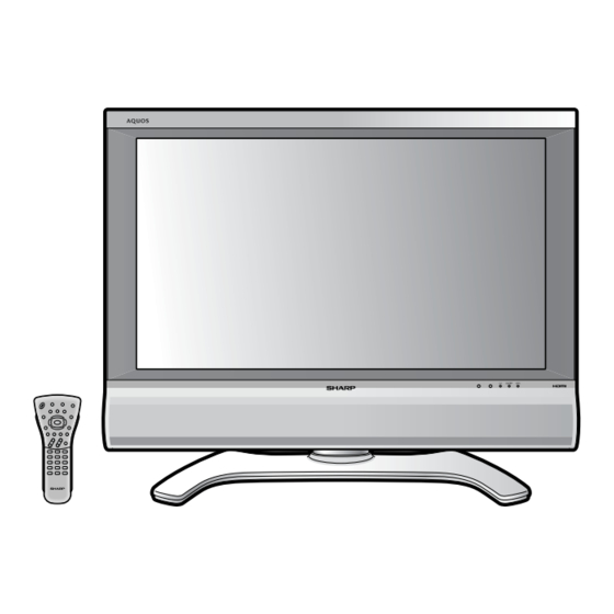
LCD COLOUR
TELEVISION
LC-26P50E
LC-32P50E
LC-37P50E
LC-26P50E
LC-32P50E
LC-37P50E
Page
Advertisement
Table of Contents

Related Manuals for Sharp LC-32P50E


Summary of Contents for Sharp LC-32P50E
-
Page 1: Table Of Contents
LC-26P50E LC-32P50E LC-37P50E SERVICE MANUAL LCD COLOUR TELEVISION LC-26P50E LC-32P50E LC-37P50E MODELS In the interests of user-safety (Required by safety regulations in some countries) the set should be restored to its original condition and only parts identical to those specified should be used. -
Page 2: Important Service Safety Precaution
LC-26P50E LC-32P50E LC-37P50E IMPORTANT SERVICE SAFETY PRECAUTION Ë Service work should be perfomed only by qualified service technicians who are thor- oughly familiar with all safety checks and the servicing guidelines which follow: WARNING ground, such as electrical conduit or electrical ground connected to an earth ground. - Page 3 LC-26P50E LC-32P50E LC-37P50E Precautions for using lead-free solder 1 Employing lead-free solder “PWBs"of this model employs lead-free solder. The LF symbol indicates lead-free solder, and is attached on the PWBs and service manuals. The alphabetical character following LF shows the type of lead-free solder.
-
Page 4: Specifications
25 kg (Display with stand) • As a part of policy of continuous impr ovement, SHARP reserves the right to make design and specification changes for product impr ovement without prior notice. The per formance specification figur es indicated ar e nominal values of production... -
Page 5: Operation Manual
LC-26P50E LC-32P50E LC-37P50E Operation Manual... - Page 6 LC-26P50E LC-32P50E LC-37P50E...
- Page 7 LC-26P50E LC-32P50E LC-37P50E...
-
Page 8: Dimensions
LC-26P50E LC-32P50E LC-37P50E Dimensions LC-26/32/37P50E (402) / [432] / ((453)) ( ) : LC-26P50E [ ] : LC-32P50E (( )) : LC-37P50E : LC-26/32/37 P50E (560) / [631] / ((671)) (674) / [804] / ((926)) (567.9) / [700.4] / ((822.6)) -
Page 9: Removing Of Major Parts
LC-26P50E LC-32P50E LC-37P50E REMOVING OF MAJOR PARTS (LC-26P50E) 1. Remove the Terminal Cover1. 2. Remove the 1 lock screw 2 and detach the ID Cover. 3. Remove the 2 lock screws 3 and detach the Hinge Cover. 4. Remove the 4 lock screws 4 and detach the stand. - Page 10 LC-26P50E LC-32P50E LC-37P50E 9. Unplug the FFC/FPC wires from SC4651, SC4652, and SC1202 - SC3701. 10.Unplug the connecting cables from these connectors: CN702, CN1701, CN1702, CN1703, CN1704, CN1705, P5700, P1201, and P3900. 11.Remove the 9 lock screws 9 and detach the Power Unit.
- Page 11 LC-26P50E LC-32P50E LC-37P50E 19.Loosen the 6 inverter unit ass’y fixing screws i, and unplug the connecting cables from the 8 lamp wire connectors to remove the inverter unit and inverter shield. 20.Remove the 2 lock screws o and detach the LCD Unit.
- Page 12 LC-26P50E LC-32P50E LC-37P50E REMOVING OF LCD PANEL UNIT (LC-26P50E) 21.Remove the 4 LCD Panel unit lock screws p and detach the LCD Panel unit. Detach the Difusion Sheets and Difusion Panel. 22.Remove the 6 lock screws a and 4 lock screws s, and detach the Panel fixing Angles from Panel Holder.
- Page 13 LC-26P50E LC-32P50E LC-37P50E REMOVING OF MAJOR PARTS (LC-32/37P50E) 1. Remove the Terminal Cover1. 2. Remove the 1 lock screw 2 and detach the ID Cover. 3. Remove the 2 lock screws 3 and detach the Hinge Cover. 4. Remove the 4 lock screws 4 and detach the stand.
- Page 14 LC-26P50E LC-32P50E LC-37P50E 10.Unplug the FFC/FPC wires from SC4651, SC4652, and SC1202 - SC3701. 11.Unplug the connecting cables from these connectors: CN702, CN1701, CN1702, CN1703, CN1704, CN1705, P5700, P1201, and P3900. 12.Remove the 9 lock screws 9 and detach the Power Unit.
- Page 15 LC-37P50E 18.Loosen the 9 (LC-32P50E) / 10 (LC-37P50E) inverter unit ass’y fixing screws u, and unplug the connecting cables from the 10 (LC-32P50E) / 11 (LC-37P50E) lamp wire connectors to remove the inverter unit and inverter shield. 19.Remove the 3 lock screws i and detach the LCD Unit.
- Page 16 20.Remove the 4 LCD Panel Unit Ass’y lock screws o and detach the LCD Panel Unit Assembly. 21.Remove the LCD Panel Unit lock screws (p:8pcs., a:12pcs., s:4pcs. for LC-32P50E, 12pcs. for LC-37P50E). 22.Remove the 2 Glass Fixing Angle lock screws d and detach the Glass Fixing Angle. Remove 4 Source PWB lock clips f.
- Page 17 LC-26P50E LC-32P50E LC-37P50E 23.Remove the 2 Panel Holder lock screws g and detach the Panel Holder. 24.Detach the Difusion Sheets and Difusion Panel. 25.Remove the 6 Lapm Holder lock screws h and detach the Lamp Holders. 26.Detach the Lamps. Back Light Chassis...
-
Page 18: Adjustment Procedure
1.After replacement of any PWB and/or IC for repair, note the following. When replacing the following units, be sure to prepare the new units loaded with updated software. AV-UNIT : DUNTKD187WE01/02/03/04/05(LC-26P50E/K/F/I/R) : DUNTKD187WE07/08/10/11/12(LC-32P50E/K/F/I/R) : DUNTKD187WE14/16/17/18/19(LC-37P50E/K/F/I/R) MAIN-UNIT : DUNTKD186FE01(LC-26P50E) : DUNTKD186FE02(LC-32P50E) : DUNTKD186FE03(LC-37P50E) 2.Upgrading of each microprocessor software... - Page 19 LC-26P50E LC-32P50E LC-37P50E 3. Entering and exiting the adjustment process mode (1) Unplug the AC power cord of running TV set to force off the power. (2) While holding down the "VOL (–)" and "INPUT" keys on the set at once, plug in the AC power cord to turn on the power.
-
Page 20: Adjustment Process Mode Menu
LC-26P50E LC-32P50E LC-37P50E 5. Adjustment process mode menu The character string in brackets [ ] will appear as a page title in the adjustment process menu header. Page Line Item Description Remarks (adjustment detail, etc.) 1/12 [INFO] Main Version 1.xx (xx/xx/xxx) - Page 21 LC-26P50E LC-32P50E LC-37P50E 8/12 [TUNER] TUNER TEST ENTER 9/12 [M GAMMA INFO] M GAMMA IN 1 W/B adjustment, gradation 1 input setting M GAMMA IN 2 W/B adjustment, gradation 2 input setting M GAMMA IN 3 W/B adjustment, gradation 3 input setting...
- Page 22 LC-26P50E LC-32P50E LC-37P50E 6. Special features ERROR STANDBY CAUSE (Page 1/12) Display of a operating hours of the last standby. The cause (code) of the last standby is recorded in EEPROM whenever possible. Checking this code will be useful in finding a problem when you repair the set in trouble.
- Page 23 LC-26P50E LC-32P50E LC-37P50E (4) PAL signal & tuner adjustment Adjustment point Adjustment conditions Adjustment procedure » Feed the PAL full field color bar signal (75% color saturation) to EXT3 Setting [Signal] VIDEO IN. » Feed the RF signal (PAL color bar) to TUNER.
- Page 24 LC-26P50E LC-32P50E LC-37P50E (7) ADC adjustment (Component 15K) Adjustment point Adjustment conditions Adjustment procedure » Feed the COMPONENT 15K 100% full field color bar signal (100% color Adjustment [Signal] saturation) to EXT3 COMPONENT IN. COMP15K, 50Hz 100%Full Field Color Bar...
-
Page 25: Adjustment Of White Balance
LC-26P50E LC-32P50E LC-37P50E (10) ADC adjustment (SCART RGB) Adjustment point Adjustment conditions Adjustment procedure » Feed the full field color bar signal to EXT1 SCART RGB IN. Adjustment [Signal] Full Field Color Bar [Terminal] EXT1 SCART IN 100% white Black Auto adjustment Adjustment process page 7 Bring the cursor on [ËRGB ADJ] and press [OK]. -
Page 26: Initialization To Factory Settings
LC-26P50E LC-32P50E LC-37P50E 6) Take the same steps as in 5) for the following. 1 Set Point 2 to the specified gradation "136". Multiply the G initial value "B2" of Point 2 by ["A" / Gradation "136" of Point 2] to have the G setting C2 of Point 2. - Page 27 LC-26P50E LC-32P50E LC-37P50E 10. Display adjustment procedure 10-1. Procedural steps Enter the display process mode. Adjust the common bias. 10-2. Entering and exiting the display process mode (1)While holding down the "VOL (+)" and "P (Ù)" keys at once, plug in the AC power cord to turn on the power.
- Page 28 LC-26P50E LC-32P50E LC-37P50E 10-5. Lamp error detection (1) Function This LCD color TV set incorporates a lamp error detection feature that automatically turns off the power for safety under abnormal lamp or lamp circuit conditions. If by any chance anything is wrong with the lamp or lamp circuit or if the lamp error detection feature is activated for some reason, the following will result.
- Page 29 LC-26P50E LC-32P50E LC-37P50E 10-6. List of adjustment process modes (Display) (Examples LC-32P50E)
- Page 30 LC-26P50E LC-32P50E LC-37P50E First layer Page Item Setting range Initial value Reference Description AD value Table of CSLEVEL 0000 0000 0000 CS Level adjustment contents COM BIAS 0~1023 0850 0860 Common bias adjustment ERR STBY "Show the cause type when entering STANDBY due to a problem."...
- Page 31 LC-26P50E LC-32P50E LC-37P50E VL 159 0~1023 *3 282/278/279 0278 VL 191 0~1023 *3 254/249/250 0249 VL 247 0~1023 *3 098/086/086 0086 PATTERN PATTERN1 0~1/0~E Show test pattern. PATTERN2 0~1/0~C Show test pattern. PATTERN3 0~1/0~5 Show QS test pattern. PATTERN4 0~1/0~5 Show test pattern.
-
Page 32: Trouble Shooting Table
LC-26P50E LC-32P50E LC-37P50E TROUBLE SHOOTING TABLE o power-up even if the power is turned on (Front LED does not changed from red to green) Connect the power cable and harness properly, and turn on the re the power cable and harness in the unit properly power. - Page 33 LC-26P50E LC-32P50E LC-37P50E TROUBLE SHOOTING TABLE (Continued) o sound (1) (during the reception of TV broadcasting) o audio output during UHF/VHF reception Confirmation of the settings: 1) Is the volume set to MI or MUTE on the remote control? ¥¥¥ Set the desired volume.
- Page 34 LC-26P50E LC-32P50E LC-37P50E TROUBLE SHOOTING TABLE (Continued) o sound (3) (output to external devices) No audio output from No audio output from the No audio output from No audio output from EXT-3 headphones S ART-1 (EXT-1) S ART-2 (EXT-2) Is there audio output on pins...
- Page 35 LC-26P50E LC-32P50E LC-37P50E TROUBLE SHOOTING TABLE (Continued) o sound (4) (from external input devices) o external audio input o external audio input o external audio input signal o external audio input signal o external audio input signal which is sent...
- Page 36 LC-26P50E LC-32P50E LC-37P50E TROUBLE SHOOTING TABLE (Continued) On input of the tuner (U/V)> No picture (1) o picture appears on LCD during the tuner (U/V) reception. Confirmation of the settings: 1) Is "I PUT SOURCE" button on the remote control set up correctly? ¥¥¥ See the operation manual and set "I PUT SOURCE" to "TV".
- Page 37 LC-26P50E LC-32P50E LC-37P50E TROUBLE SHOOTING TABLE (Continued) During external connection> No picture (2) CART1: CART2: CART2: No picture appears on EXT1-connected No picture from EXT1 appears on EXT2- No picture from EXT3 appears on EXT2- monitor during the tuner (U/V) reception.
- Page 38 LC-26P50E LC-32P50E LC-37P50E TROUBLE SHOOTING TABLE (Continued) When EXT1 is used for external input> No picture (3) XT1 in trouble. XT1-RGB in trouble. XT1-Y/C in trouble. Confirmation of the settings: 1) Is "INPUT SOURC " button on the remote control set up correctly?áááSee the operation manual and set "INPUT SOURC " to " XT1".
- Page 39 LC-26P50E LC-32P50E LC-37P50E TROUBLE SHOOTING TABLE (Continued) When EXT2 is used for external input> No picture (4) XT2 in trouble. XT2-RGB in trouble. XT2-Y/C in trouble. Confirmation of the settings: 1) Is "INPUT SOURC " button on the remote control set up correctly?áááSee the operation manual and set "INPUT SOURC " to " XT2".
- Page 40 LC-26P50E LC-32P50E LC-37P50E TROUBLE SHOOTING TABLE (Continued) When EXT3 is used for external input> No picture (5) XT3-COMPON NT (Y, Pb and Pr) in XT3 in trouble. XT3-Y/C in trouble. trouble. Confirmation of the settings: 1) Is "INPUT SOURC " button on the remote control set up correctly?áááSee the operation manual and set "INPUT SOURC "...
- Page 41 LC-26P50E LC-32P50E LC-37P50E TROUBLE SHOOTING TABLE (Continued) When EXT4 is used for external input> No picture (6) XT4 (HDMI) in trouble. Confirmation of the settings: 1) Is "INPUT SOURC " button on the remote control set up correctly?áááSee the operation manual and set "INPUT SOURC " to " XT4".
- Page 42 LC-26P50E LC-32P50E LC-37P50E TROUBLE SHOOTING TABLE (Continued) DISPLAY AREA > o picture and no sound Is the power Replace the Is the power LED lit green? Is the power LED flashing red? cord normal? power cord. Did it flash once? Go to "The backlight does not light".
- Page 43 LC-26P50E LC-32P50E LC-37P50E TROUBLE SHOOTING TABLE (Continued) he backlight does not light. Replace the fluorescent lamps that do not Check the fluorescent lamps that do not o all fluorescent lamps fail to light? light. light. In POWER UNIT: Replace the blown fuse(F703) or R1765...
- Page 44 LC-26P50E LC-32P50E LC-37P50E TROUBLE SHOOTING TABLE (Continued) he backlight turns on, but no picture appears on the LCD. Is the power supplied to M IN-PWB? (P1800: +14V/UR4.5V/UR+3.5/BU+3.3V) Check IC4104 (DC/ C-CONV) djustment process menu: When the P TTERN Is the VLS voltage (VLS15V) of and its peripheral circuits.
- Page 45 LC-26P50E LC-32P50E LC-37P50E hen the QC drive is turned on, noise appears in the moving picture. Is IC4501 (E2PROM) mounted properly? Mount IC4501 (E2PROM) properly. Is the amplitude of each terminal of IC4503 (64M-SDR M) Check IC4502 (LCD-CTL) thru IC4503 (64M-SDR M) and their approx.
-
Page 46: Major Ic Infomations
LC-26P50E LC-32P50E LC-37P50E MAJOR IC INFOMATIONS ●IC1203 VIDEO-SELECTOR, VHiMM1630EQ-1 This is a video switch with I2C bus control developed for use in high resolution TVs and projection TVs. It can switch 4 color difference signal lines (component signal), 5 S video signal lines and 8 composite signal lines. - Page 47 LC-26P50E LC-32P50E LC-37P50E ●IC1905 24bit-DAC, VHiAK4384ET-1 The AK4384 is a 24-bit DAC that provides for better cost performance in digital audio equipment. The ∆Σ modulator is equipped with the brand-new advanced multi-bit system for a wide dynamic range. The built-in post-filter is of switch-cum-capacitor-filter (SCF) type to cope with the accuracy problem by clock jitters.
- Page 48 LC-26P50E LC-32P50E LC-37P50E ●IC4502 LCD-CONT, RH-iXB326WJZZ Equipped with LVDS input and RSDS output interfaces and overdrive support, this LCD control IC drives the HE, WXGA, XGA, WVGA and VGA panels. Its main functions include: 1) The LCD drive timing signal generating circuit processes the pixel clock, horizontal and vertical sync signals, and display enable signal to produce various signals for driving the LCD source and gate driver.
- Page 49 LC-26P50E LC-32P50E LC-37P50E - M E M O -...
-
Page 50: Overall Wiring Diagram
LC-26P50E LC-26P50E LC-32P50E LC-32P50E LC-37P50E LC-37P50E OVERALL WIRING DIAGRAM... -
Page 51: Block Diagram
LC-26P50E LC-26P50E LC-32P50E LC-32P50E LC-37P50E LC-37P50E BLOCK DIAGRAM-1/2 SYSTEM BLOCK DIAGRAM... - Page 52 LC-26P50E LC-26P50E LC-32P50E LC-32P50E LC-37P50E LC-37P50E BLOCK DIAGRAM-2/2 POWER-SOURCE BLOCK DIAGRAM...
- Page 53 LC-26P50E LC-26P50E LC-32P50E LC-32P50E LC-37P50E LC-37P50E PRINTED WIRING BOARD ASSEMBLIES Ë MAIN Unit-1/4 (Side-A)
- Page 54 LC-26P50E LC-26P50E LC-32P50E LC-32P50E LC-37P50E LC-37P50E Ë MAIN Unit-2/4 (Chip Parts Side-A)
- Page 55 LC-26P50E LC-26P50E LC-32P50E LC-32P50E LC-37P50E LC-37P50E Ë MAIN Unit-3/4 (Side-B)
- Page 56 LC-26P50E LC-26P50E LC-32P50E LC-32P50E LC-37P50E LC-37P50E Ë MAIN Unit-4/4 (Chip Parts Side-B)
- Page 57 LC-26P50E LC-26P50E LC-32P50E LC-32P50E LC-37P50E LC-37P50E Ë AV Unit-1/4 (Side-A)
- Page 58 LC-26P50E LC-26P50E LC-32P50E LC-32P50E LC-37P50E LC-37P50E Ë AV Unit-2/4 (Chip Parts Side-A) LUG5702 P3900 C3928 R3917 C3927 R5700 LUG5701 Q5700 P5700 C3931 C3930 Q5701 R1141 C1112 C1122 R1366 R5701 D3903 C3913 X1100 C3914 SC1202 R3913 R1367 C1130 C3919 C1121 Q1217...
- Page 59 LC-26P50E LC-26P50E LC-32P50E LC-32P50E LC-37P50E LC-37P50E Ë AV Unit-3/4 (Side-B)
- Page 60 LC-26P50E LC-26P50E LC-32P50E LC-32P50E LC-37P50E LC-37P50E Ë AV Unit-4/4 (Chip Parts Side-B) TL5706 TL5702 TL5700 TL5707 TL5703 TL5701 TL5705 TL1109 TL1112 TL1298 TL5704 TL1307 TL1297 TL1305 TL1313 TL1303 TL1296 TL1309 TL1310 TL1302 TL1299 TL1314 TL1312 TL1259 TL1110 TL1308 TL1300 TL1301...
- Page 61 LC-26P50E LC-32P50E LC-37P50E Ë R/C LED Unit (Side-A) (Chip Parts Side-A) (Side-B) (Chip Parts Side-B)
-
Page 62: Key Unit
LC-26P50E LC-32P50E LC-37P50E Ë KEY Unit (Side-A) (Chip Parts Side-A) (Side-B) (Chip Parts Side-B) - Page 63 LC-26P50E LC-32P50E LC-37P50E Ë POWER Unit (Side-A)
- Page 64 LC-26P50E LC-32P50E LC-37P50E Ë POWER Unit (Side-B)
- Page 65 LC-26P50E LC-26P50E LC-32P50E LC-32P50E LC-37P50E LC-37P50E Ë INVERTER Unit (LC-26P50E) (Side-A) PKG-2 PKG-4 PKG-3...
- Page 66 LC-26P50E LC-26P50E LC-32P50E LC-32P50E LC-37P50E LC-37P50E Ë INVERTER Unit (LC-26P50E) (Side-B) PKG-2 PKG-4 PKG-3...
- Page 67 LC-26P50E LC-26P50E LC-32P50E LC-32P50E LC-37P50E LC-37P50E Ë INVERTER Unit (LC-32P50E) (Side-A) PKG-2 PKG-4 PKG-3 PKG-5...
- Page 68 LC-26P50E LC-26P50E LC-32P50E LC-32P50E LC-37P50E LC-37P50E Ë INVERTER Unit (LC-32P50E) (Side-B) PKG-2 PKG-4 PKG-3 PKG-5...
- Page 69 LC-26P50E LC-26P50E LC-32P50E LC-32P50E LC-37P50E LC-37P50E Ë INVERTER Unit (LC-37P50E) (Side-A) PKG-2 PKG-4 PKG-3 PKG-6...
- Page 70 LC-26P50E LC-26P50E LC-32P50E LC-32P50E LC-37P50E LC-37P50E Ë INVERTER Unit (LC-37P50E) (Side-B) PKG-2 PKG-4 PKG-3 PKG-6...
-
Page 71: Printed Wiring Board Assemblies
— IC4501 RH-iXB438WJZZY J I.C.(LC-32P50E) DUNTKD188WE12 – KEY Unit(LC-32P50R) — IC4501 RH-iXB439WJZZY J I.C.(LC-37P50E) DUNTKD189WE07 – R/C, LED Unit(LC-32P50E) — IC4502 RH-iXB326WJZZQ J IXB326 DUNTKD189WE08 – R/C, LED Unit(LC-32P50K) — IC4503 RH-iXB029WJZZQ J MT48LC2M32B2P6 DUNTKD189WE10 – R/C, LED Unit(LC-32P50F) —... - Page 72 LC-26P50E LC-32P50E LC-37P50E ★ ★ Ref. No. Part No. Description Code Ref. No. Part No. Description Code C1809 VCEASY1CN107MY J 100 Electrolytic DUNTKD186FE01/02/03(LC-26/32/37P50E) C1810 VCKYCY1EF104ZY J 0.1 Ceramic C1811 VCEASY1CN226MY J 22 Electrolytic MAIN Unit (Continued) C1812 VCEASY1CN107MY J 100 Electrolytic C1813 VCKYCY1EF104ZY J 0.1...
- Page 73 LC-26P50E LC-32P50E LC-37P50E ★ ★ Ref. No. Part No. Description Code Ref. No. Part No. Description Code C3724 VCKYCY1EF104ZY J 0.1 Ceramic DUNTKD186FE01/02/03(LC-26/32/37P50E) C3725 VCKYCY1EB473KY J 0.047 25V Ceramic C3726 VCKYCY1EF104ZY J 0.1 Ceramic MAIN Unit (Continued) C3727 VCKYCY1EF104ZY J 0.1 Ceramic C3728 VCKYCY1EF104ZY J 0.1...
- Page 74 LC-26P50E LC-32P50E LC-37P50E ★ ★ Ref. No. Part No. Description Code Ref. No. Part No. Description Code R1808 VRS-CY1JF103JY J 10k 1/16W Metal Oxide DUNTKD186FE01/02/03(LC-26/32/37P50E) R1809 VRS-CY1JF103JY J 10k 1/16W Metal Oxide R1810 VRS-CY1JF103JY J 10k 1/16W Metal Oxide MAIN Unit (Continued)
- Page 75 LC-26P50E LC-32P50E LC-37P50E ★ ★ Ref. No. Part No. Description Code Ref. No. Part No. Description Code DUNTKD186FE01/02/03(LC-26/32/37P50E) R3319 VRS-CK1JF680JY J 68 1/16W Metal Oxide R3320 VRS-CZ1JF330JY J 33 1/16W Metal Oxide MAIN Unit (Continued) R3321 VRS-CK1JF680JY J 68 1/16W Metal Oxide...
- Page 76 LC-26P50E LC-32P50E LC-37P50E ★ ★ Ref. No. Part No. Description Code Ref. No. Part No. Description Code R4129 VRS-CY1JF100JY J 10 1/16W Metal Oxide DUNTKD186FE01/02/03(LC-26/32/37P50E) R4130 VRS-CY1JF100JY J 10 1/16W Metal Oxide R4131 VRS-CY1JF100JY J 10 1/16W Metal Oxide MAIN Unit (Continued)
- Page 77 LC-26P50E LC-32P50E LC-37P50E ★ ★ Ref. No. Part No. Description Code Ref. No. Part No. Description Code P1800 QCNCMA492WJZZ J Connector, 24pin (PB) DUNTKD186FE01/02/03(LC-26/32/37P50E) P1804 QEARBA005WJFMY J Ground-Part SC2001 QSOCNA480WJQZY J Socket, 40pin MAIN Unit (Continued) SC3701 QCNCWA284WJZZY J Connector, 50pin (To AV)
- Page 78 LC-26P50E LC-32P50E LC-37P50E ★ ★ Ref. No. Part No. Description Code Ref. No. Part No. Description Code DIODES DUNTKD187WE01/02/03/04/05(LC-26P50E) D1100 VHD1SS390++-1Y J D1SS390 DUNTKD187WE07/08/10/11/12(LC-32P50E) D1101 RH-EX0677GEZZY J Zener Diode, 33V D1102 RH-EX1232CEZZY J Zener Diode, 3.3V D1103 VHD1SS390++-1Y J D1SS390...
- Page 79 LC-26P50E LC-32P50E LC-37P50E ★ ★ Ref. No. Part No. Description Code Ref. No. Part No. Description Code DUNTKD187WE01/02/03/04/05(LC-26P50E) C1216 VCKYTV1CB105KY J 1 Ceramic C1217 VCKYTV1CB105KY J 1 Ceramic DUNTKD187WE07/08/10/11/12(LC-32P50E) C1218 VCKYCY1HB102KY J 1000p 50V Ceramic C1219 VCCCCY1HH560JY J 56p Ceramic...
- Page 80 LC-26P50E LC-32P50E LC-37P50E ★ ★ Ref. No. Part No. Description Code Ref. No. Part No. Description Code DUNTKD187WE01/02/03/04/05(LC-26P50E) C1954 VCKYCY1EF104ZY J 0.1 Ceramic C1955 VCKYCY1HB102KY J 1000p 50V Ceramic DUNTKD187WE07/08/10/11/12(LC-32P50E) C1957 VCKYCY1EF104ZY J 0.1 Ceramic C1958 VCKYCY1HB102KY J 1000p 50V...
- Page 81 LC-26P50E LC-32P50E LC-37P50E ★ ★ Ref. No. Part No. Description Code Ref. No. Part No. Description Code DUNTKD187WE01/02/03/04/05(LC-26P50E) C5712 VCKYCY1EF104ZY J 0.1 Ceramic C5713 VCKYCY1HB102KY J 1000p 50V Ceramic DUNTKD187WE07/08/10/11/12(LC-32P50E) C5719 VCKYCY1EF104ZY J 0.1 Ceramic C5720 VCKYCY1EF104ZY J 0.1 Ceramic...
- Page 82 LC-26P50E LC-32P50E LC-37P50E ★ ★ Ref. No. Part No. Description Code Ref. No. Part No. Description Code DUNTKD187WE01/02/03/04/05(LC-26P50E) R1284 VRS-CY1JF000JY 1/16W Metal Oxide R1285 VRS-TW2ED750JY J 75 1/4W Metal Oxide DUNTKD187WE07/08/10/11/12(LC-32P50E) R1286 VRS-CY1JF101JY J 100 1/16W Metal Oxide R1287 VRS-CY1JF101JY...
- Page 83 LC-26P50E LC-32P50E LC-37P50E ★ ★ Ref. No. Part No. Description Code Ref. No. Part No. Description Code DUNTKD187WE01/02/03/04/05(LC-26P50E) R2514 VRS-CJ1JF470JY J 47 1/16W Metal Oxide R2515 VRS-CY1JF222JY J 2.2k 1/16W Metal Oxide DUNTKD187WE07/08/10/11/12(LC-32P50E) R2516 VRS-CJ1JF102JY J 1k 1/16W Metal Oxide...
- Page 84 LC-26P50E LC-32P50E LC-37P50E ★ ★ Ref. No. Part No. Description Code Ref. No. Part No. Description Code DUNTKD187WE01/02/03/04/05(LC-26P50E) DUNTKD188WE01/02/03/04/05(LC-26P50E) DUNTKD187WE07/08/10/11/12(LC-32P50E) DUNTKD188WE07/08/10/11/12(LC-32P50E) DUNTKD187WE14/16/17/18/19(LC-37P50E) DUNTKD188WE14/16/17/18/19(LC-37P50E) AV Unit (Continued) KEY Unit FB1206 RBLN-0062TAZZY J Ferrite Beads DIODES FB1207 RBLN-0062TAZZY J Ferrite Beads D151...
-
Page 85: Inverter Unit
LC-26P50E LC-32P50E LC-37P50E ★ ★ Ref. No. Part No. Description Code Ref. No. Part No. Description Code DUNTKD189WE01/02/03/04/05(LC-26P50E) RUNTKA151WJZZ(LC-26P50E) DUNTKD189WE07/08/10/11/12(LC-32P50E) INVERTER Unit DUNTKD189WE14/16/17/18/19(LC-37P50E) INTEGRATED CIRCUIT Z7501 9JG00034070407 J IC, STR-H2013 R/C, LED Unit TRANSISTORS Q7501 9JG00034094624 J 2SK3561 INTEGRATED CIRCUIT... - Page 86 LC-26P50E LC-32P50E LC-37P50E ★ ★ Ref. No. Part No. Description Code Ref. No. Part No. Description Code C7542 9JG00034033099 J 100p Ceramic RUNTKA151WJZZ(LC-26P50E) C7543 9JG00034033099 J 100p Ceramic C7544 9JG00034033099 J 100p Ceramic INVERTER Unit (Continued) C7545 9JG00034033099 J 100p...
- Page 87 LC-26P50E LC-32P50E LC-37P50E ★ ★ Ref. No. Part No. Description Code Ref. No. Part No. Description Code R7558 9JG00034016321 J 47k 1/10W Resistor RUNTKA151WJZZ(LC-26P50E) R7559 9JG00034016240 J 10k 1/10W Resistor R7561 9JG00034005273 J 1k 1/4W Resistor INVERTER Unit (Continued) R7562 9JG00034004579...
- Page 88 LC-26P50E LC-32P50E LC-37P50E ★ ★ Ref. No. Part No. Description Code Ref. No. Part No. Description Code RUNTKA151WJZZ(LC-26P50E) RUNTKA152WJZZ(LC-32P50E) INVERTER Unit (Continued) INVERTER Unit INTEGRATED CIRCUIT PN7513 9JG00034092923 J Connector, IMSA-9210B-1- 11Z789-PT1 Z7501 9JG00034070407 J IC, STR-H2013 PN7514 9JG00034092958 J Connector, IMSA-9210B-1-...
- Page 89 LC-26P50E LC-32P50E LC-37P50E ★ ★ Ref. No. Part No. Description Code Ref. No. Part No. Description Code C7530 9JG00034090165 J 22p 6.3kV Ceramic RUNTKA152WJZZ(LC-32P50E) C7531 9JG00034090165 J 22p 6.3kV Ceramic C7532 9JG00034090165 J 22p 6.3kV Ceramic INVERTER Unit (Continued) C7533 9JG00034090165 J 22p 6.3kV Ceramic...
- Page 90 LC-26P50E LC-32P50E LC-37P50E ★ ★ Ref. No. Part No. Description Code Ref. No. Part No. Description Code R7545 9JG00034003750 J 1k 1/10W Resistor RUNTKA152WJZZ(LC-32P50E) R7546 9JG00034003750 J 1k 1/10W Resistor R7547 9JG00034003750 J 1k 1/10W Resistor INVERTER Unit (Continued) R7548 9JG00034003750...
- Page 91 LC-26P50E LC-32P50E LC-37P50E ★ ★ Ref. No. Part No. Description Code Ref. No. Part No. Description Code RUNTKA152WJZZ(LC-32P50E) RUNTKA154WJZZ(LC-37P50E) INVERTER Unit (Continued) INVERTER Unit INTEGRATED CIRCUIT R7655 9JG00034005273 J 1k 1/4W Resistor Z7501 9JG00034070407 J IC, STR-H2013 R7657 9JG00034016321 J 47k 1/10W Resistor R7658 9JG00034003955 J 4.7k 1/10W Resistor...
- Page 92 LC-26P50E LC-32P50E LC-37P50E ★ ★ Ref. No. Part No. Description Code Ref. No. Part No. Description Code C7524 9JG00034116180 J 18p Ceramic RUNTKA154WJZZ(LC-37P50E) C7525 9JG00034116180 J 18p Ceramic C7526 9JG00034116180 J 18p Ceramic INVERTER Unit (Continued) C7527 9JG00034116180 J 18p...
- Page 93 LC-26P50E LC-32P50E LC-37P50E ★ ★ Ref. No. Part No. Description Code Ref. No. Part No. Description Code R7533 9JG00034041997 J 1.8k 1/10W Resistor RUNTKA154WJZZ(LC-37P50E/K/F/I/R) R7534 9JG00034005974 J 10k 1/10W Resistor R7535 9JG00034003750 J 1k 1/10W Resistor INVERTER Unit (Continued) R7536 9JG00034004579...
- Page 94 LC-26P50E LC-32P50E LC-37P50E ★ ★ Ref. No. Part No. Description Code Ref. No. Part No. Description Code RUNTKA154WJZZ(LC-37P50E) RDENCA122WJZZ(LC-26/32P50E) INVERTER Unit (Continued) RDENCA133WJZZ(LC-37P50E) POWER Unit R7631 9JG00034003920 1/10W Resistor R7637 9JG00034005273 J 1k 1/4W Resistor R7638 9JG00034004293 J 100 1/4W...
- Page 95 LC-26P50E LC-32P50E LC-37P50E ★ ★ Ref. No. Part No. Description Code Ref. No. Part No. Description Code C716 9JG00034002126 J 100p Ceramic RDENCA122WJZZ(LC-26/32P50E) C717 9JG00034019452 J 1000p 1kV Ceramic C719 9JG00034094233 J 150 450V Electrolytic RDENCA133WJZZ(LC-37P50E) C721 9JG00034006601 J 0.47...
- Page 96 LC-26P50E LC-32P50E LC-37P50E ★ ★ Ref. No. Part No. Description Code Ref. No. Part No. Description Code R761 9JG00034003904 J 10k 1/8W Resistor RDENCA122WJZZ(LC-26/32P50E) R762 9JG00034016240 J 10k 1/10W Resistor R763 9JG00034016240 J 10k 1/10W Resistor RDENCA133WJZZ(LC-37P50E) R764 9JG00034016240 J 10k 1/10W Resistor...
- Page 97 LC-26P50E LC-32P50E LC-37P50E ★ ★ Ref. No. Part No. Description Code Ref. No. Part No. Description Code RDENCA122WJZZ(LC-26/32P50E) RDENCA133WJZZ(LC-37P50E) POWER Unit (Continued) R1757 9JG00034001421 J 10k 1/4W Carbon R1758 9JG00034001421 J 10k 1/4W Carbon R1759 9JG00034004021 J 470 1/10W Resistor R1760 9JG00034003866 J 6.8k 1/10W Resistor...
-
Page 98: Cabinet And Mechanical Parts
J Lamp, x8 Not Available – Front Cabinet — 5-6-3-2 QCNW-D683WJQZ J Connector, x7 GCOVAB240WJSA S R/C, LED Decoration Cover 5-6-3-3 QCNW-D686WJQZ J Connector HBDGBA015WJSA S Badge, ”SHARP” PSPAHA323WJZZ S Mask Spacer, x2 5-6-4 LHLDZA592WJKZ J Lamp Holder, x2 PSPAHA324WJZZ... - Page 99 LC-26P50E LC-32P50E LC-37P50E ★ ★ Ref. No. Part No. Description Code Ref. No. Part No. Description Code CABINET AND MECHANICAL PARTS (LC-26P50E/K/F/I/R) (Continued) QCNW-D843WJQZ S Connecting Cord, MAIN-POWER (PB) QCNW-D844WJQZ S Connecting Cord, MAIN-POWER (PC) QCNW-D845WJQZ S Connecting Cord, INV_GND-GND...
- Page 100 LC-26P50E LC-32P50E LC-37P50E CABINET AND MECHANICAL PARTS (LC-26P50E) 5-6-5 5-6-7 5-6-7 5-7-2 5-6-1-11 5-6-1-2 5-6-1-10 5-6-1-11 5-6-1 5-6-1-11 5-6-1-4 5-6-1-6 5-6-1-9 5-6-1-11 5-6-1-3 5-6-1-8 5-6-3-2 5-6-3-1 5-6-1-5 5-6-1-11 5-6-8 5-6-1-7 5-6-1-8 5-6-4 5-6-8 5-6-4 46 52 4-1-1 4-1-2 4-2-1 4-2-2...
- Page 101 – KEY Unit (LC-32P50R) — 5-2-8 XBPS730P06WS0 J Screw, x4 (for Stand) DUNTKD189WE07 – R/C, LED Unit (LC-32P50E) — DUNTKD189WE08 – R/C, LED Unit (LC-32P50K) — CANGTA188WJ01 J Panel Fixing Angle Ass’y (Bottom) DUNTKD189WE10 – R/C, LED Unit (LC-32P50F) —...
- Page 102 Description Code Ref. No. Part No. Description Code CABINET AND MECHANICAL PARTS (LC-32P50E/K/F/I/R) (Continued) PSPAZA848WJKZ S Cooling Sheet for IC1203 QCNCMA201WJZZ S Connecting Cord, MAIN-AV AH (B to B) QCNW-D576WJQZ S Connecting Cord, AV-KEY QCNW-D577WJQZ S Connecting Cord, AV-R/C,LED QCNW-D578WJQZ S Connecting Cord, AV-SP (SP)
- Page 103 LC-26P50E LC-32P50E LC-37P50E CABINET AND MECHANICAL PARTS (LC-32P50E) 5-7-5 5-7-6 5-7-6 5-7-2 5-7-1-3 5-7-1-1 5-7-1-8 5-7-1-10 5-7-1-7 5-7-3-2 5-7-3-1 5-7-7 5-7-1-6 5-7-1-7 5-7-4 5-7-7 48 21 5-7-4 4-1-1 4-1-2 4-2-1 4-2-2 4-2-5 4-2-4 4-2-5 4-2-3...
- Page 104 – Front Cabinet — 5-7-1-13 TCAUZA031WJZZ J Caution Label GCOVAB240WJSA S R/C, LED Decoration Cover 5-7-1-14 XBPS730P06WS0 J Screw, x17(M3*6) HBDGB3142CESB S Badge, ”SHARP” PSPAHA412WJZZ S Mask Spacer, x2 5-7-2 CHLDZA633WJ01 J Panel Holder, Ass’y PSPAHA416WJZZ S Mask Spacer, x2...
- Page 105 LC-26P50E LC-32P50E LC-37P50E ★ ★ Ref. No. Part No. Description Code Ref. No. Part No. Description Code CABINET AND MECHANICAL PARTS (LC-37P50E/K/F/I/R) (Continued) PSPAZA845WJKZ S Cooling Sheet For IC4101 PSPAZA846WJKZ S Cooling Sheet For IC4503 PSPAZA848WJKZ S Cooling Sheet For IC1203...
- Page 106 LC-26P50E LC-32P50E LC-37P50E CABINET AND MECHANICAL PARTS (LC-37P50E) 5-7-5 5-7-6 5-7-6 5-7-2 5-7-1-13 5-7-1-11 5-7-1-10 5-7-3-2 5-7-3-1 5-7-1-9 5-7-1-10 5-7-4 5-7-4 4-1-1 4-1-2 4-2-1 4-2-2 4-2-4 4-2-5 4-2-5 4-2-3...
-
Page 107: Packing Parts
S Cable Clamp TLABKA002WJZZ – Bar Code Label — LHLDWA083WJ00 S Cable Band QACCBA021WJPZ S AC Code (LC-32P50K) LC-37P50E/K/F/I/R QACCKA007WJPZ S AC Code (LC-32P50E/F/I/R) AK SPAKCB953WJZZ – Packing Case — RRMCGA387WJSA S Infrared Remote Control SPAKFA788WJZZ – Accessories Case —... -
Page 108: Packing Of The Set
LC-26P50E LC-32P50E LC-37P50E PACKING OF THE SET ★S7 ★S7 ★S2 ★S5 ★S11 ★S8 ★S6 ★S7 ★S3 ★S7 ★S4 ★S9 ★S12 ★S10 (LC-32P50F/37P50F only) ★S1 ★ Not Replacement item... - Page 109 LC-26P50E LC-32P50E LC-37P50E COPYRIGHT © 2005 BY SHARP CORPORATION ALL RIGHTS RESERVED. No part of this publication may be reproduced, stored in a retrieval system, or transmitted in any form or by any means, electronic, mechanical, photocopying, recording, or otherwise, without prior written permission of the publisher.
-
Page 110: Schematic Diagram
THE SET. BE SURE TO REPLACE THESE PARTS WITH SPECIFIED ONES FOR MAINTAINING THE POWER Unit …………………………………………………………………………………D33 SAFETY AND PERFORMANCE OF THE SET. INVERTER Unit (LC-26P50E) ……………………………………………………………D35 INVERTER Unit (LC-32P50E) ……………………………………………………………D37 INVERTER Unit (LC-37P50E) ……………………………………………………………D39 R/C, LED Unit ……………………………………………………………………………………… D41... - Page 111 Ë AV Unit-1/4...
- Page 112 Ë AV Unit-2/4...
- Page 113 Ë AV Unit-3/4...
- Page 114 Ë AV Unit-4/4...
- Page 115 Ë MAIN Unit-1/8 (LC-26P50E)
- Page 116 Ë MAIN Unit-1/8 (LC-32P50E)
- Page 117 Ë MAIN Unit-1/8 (LC-37P50E)
- Page 118 Ë MAIN Unit-2/8...
- Page 119 Ë MAIN Unit-3/8...
- Page 120 Ë MAIN Unit-4/8...
- Page 121 Ë MAIN Unit-5/8...
- Page 122 Ë MAIN Unit-6/8...
- Page 123 Ë MAIN Unit-7/8...
- Page 124 Ë MAIN Unit-8/8...
- Page 125 Ë KEY Unit...
- Page 126 Ë POWER Unit...
- Page 127 Ë INVERTER Unit (LC-26P50E)
- Page 128 Ë INVERTER Unit (LC-32P50E)
- Page 129 Ë INVERTER Unit (LC-37P50E)
- Page 130 Ë R/C, LED Unit...