Table of Contents
Advertisement
Service
Manual
HIGH POWER CASSETTE PLAYER WITH FM/MW/LW TUNER
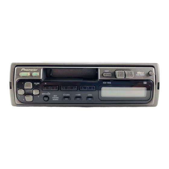
KEH-1940
KEH-1960
- This service manual should be used together with the following manual(s):
Model No.
Order No.
CX-644
CRT1800
CONTENTS
1. SAFETY INFORMATION............................................2
2. EXPLODED VIEWS AND PARTS LIST ......................2
4. PCB CONNECTION DIAGRAM................................20
5. ELECTRICAL PARTS LIST........................................28
6. ADJUSTMENT .........................................................32
PIONEER CORPORATION
PIONEER ELECTRONICS SERVICE INC.
PIONEER ELECTRONIC [EUROPE] N.V.
PIONEER ELECTRONICS ASIACENTRE PTE.LTD. 253 Alexandra Road, #04-01, Singapore 159936
C PIONEER CORPORATION 1999
KEH-1940/X1M/EW
X1M/EW
Mech. Module Remarks
2M
Cassette Mech. Module:Circuit Description, Mech.Description, Disassembly
4-1, Meguro 1-Chome, Meguro-ku, Tokyo 153-8654, Japan
P.O.Box 1760, Long Beach, CA 90801-1760 U.S.A.
Haven 1087 Keetberglaan 1, 9120 Melsele, Belgium
7. GENERAL INFORMATION.......................................34
7.1 DISASSEMBLY ..................................................34
7.2 PARTS ................................................................35
7.2.1 IC ...............................................................35
7.2.2 DISPLAY ...................................................38
8. OPERATIONS AND SPECIFICATIONS ....................39
K-ZZY. NOV. 1999 Printed in Japan
ORDER NO.
CRT2425
X1M/EW
Advertisement
Table of Contents

Related Manuals for Pioneer KEH-1940


Summary of Contents for Pioneer KEH-1940
- Page 1 PIONEER ELECTRONICS SERVICE INC. P.O.Box 1760, Long Beach, CA 90801-1760 U.S.A. PIONEER ELECTRONIC [EUROPE] N.V. Haven 1087 Keetberglaan 1, 9120 Melsele, Belgium PIONEER ELECTRONICS ASIACENTRE PTE.LTD. 253 Alexandra Road, #04-01, Singapore 159936 C PIONEER CORPORATION 1999 K-ZZY. NOV. 1999 Printed in Japan...
-
Page 2: Safety Information
KEH-1940,1960 1. SAFETY INFORMATION This service manual is intended for qualified service technicians; it is not meant for the casual do-it-yourselfer. Qualified technicians have the necessary test equipment and tools, and have been trained to properly and safely repair complex products such as those covered by this manual. - Page 3 KEH-1940,1960 NOTE: - Parts marked by “*” are generally unavailable because they are not in our Master Spare Parts List. ∇ mark on the product are used for disassembly. - Screws adjacent to - PACKING SECTION PARTS LIST Part.No Mark No. Description...
- Page 4 KEH-1940,1960 2.2 EXTERIOR...
- Page 5 KEH-1940,1960 (1) EXTERIOR SECTION PARTS LIST Mark No. Description Part No. Mark No. Description Part No. 1 Screw BSZ26P050FMC 36 Spring CBH1836 2 Screw BSZ30P055FUC 37 Spring CBH2307 3 Screw BSZ30P060FMC 38 Cover See Contrast table(2) 4 Screw BSZ30P100FMC 39 Keyboard Unit...
- Page 6 KEH-1940,1960 (2) CONTRAST TABLE KEH-1940/X1M/EW and KEH-1960/X1M/EW are constructed the same except for the following: Part No. Mark No. Description KEH-1940/X1M/EW KEH-1960/X1M/EW Chassis Unit CXB4636 CXB4637 Detach Grille Assy CXB4671 CXB4672 Button(EJECT) CAC5870 CAC5871 Button(REW) CAC5872 CAC5873 Button(FF) CAC5874 CAC5875...
- Page 7 KEH-1940,1960...
- Page 8 KEH-1940,1960 2.3 CASSETTE MECHANISM ASSY...
- Page 9 KEH-1940,1960 - CASSETTE MECHANISM ASSY SECTION PARTS LIST Mark No. Description Part No. Mark No. Description Part No. 1 Screw BSZ23P050FMC 46 Gear ENV1475 2 Washer CBG1003 47 Gear ENV1512 3 Connector(CN1) CKS2829 48 Gear ENV1513 4 Screw(M2x5) EBA1038 49 Gear ENV1502 5 Screw(M2x2.5)
-
Page 10: Block Diagram And Schematic Diagram
KEH-1940,1960 3. BLOCK DIAGRAM AND SCHEMATIC DIAGRAM 3.1 BLOCK DIAGRAM TUNER AMP UNIT TUN-L FM/AM TUNER UNIT ILL+B Q31 CF51 CF52 CF53 FM/AM MIX FM/AM IF FM IF FM IF FM RF CN301 FWD-L 41 9 10 14 15 FM/AM PROCESSOR... - Page 11 KEH-1940,1960 TUN-L ILL+B ELECTRONIC VOLUME FWD-L POWER AMP CASSETTE EQUALIZER IC 401 FWD/REV SWITCH IC 501 SN761029DL IC 201 TDA7384 LA3161P STBY MUTE FIX+B SYSPW REV-L FWD/REV MUTE SWITCH Q609 Q501 MUTE LOAD SWITCH MECHA MUTE LOAD POWER SWITCH Q502...
- Page 12 KEH-1940,1960 3.2 OVERALL CONNECTION DIAGRAM(GUIDE PAGE) Note: When ordering service parts, be sure to refer to “EXPLODED VIEWS AND PARTS LIST” or “ELECTRICAL PARTS LIST”. TUNER AMP UNIT ELECTRONIC VO Large size SCH diagram FM/AM TUNER UNIT Guide page AM : -26.0dBs FM : -16.0dBs...
-
Page 13: Keyboard Unit
KEH-1940,1960 FM : 100% 35.1dBs OLUME AM : 30% 24.1dBs TAPE : 315Hz 0dB 22.1dBs -29.0dBs BACK POWER AMP TAPE : -3.9dBs AM : -0.9dBs FM : 9.1dBs TAPE : 22.1dBs FUSE 600µH B.REMOTE KEY/LCD DRIVER CEL 1547 (1940/X1M/EW) CEL 1479... - Page 14 KEH-1940,1960...
- Page 15 KEH-1940,1960...
- Page 16 KEH-1940,1960...
- Page 17 KEH-1940,1960...
- Page 18 KEH-1940,1960 3.3 FM/AM TUNER UNIT FM/AM TUNER UN...
- Page 19 KEH-1940,1960 R UNIT...
-
Page 20: Pcb Connection Diagram
KEH-1940,1960 4. PCB CONNECTION DIAGRAM CORD ASSY 4.1 TUNER AMP UNIT NOTE FOR PCB DIAGRAMS 1. The parts mounted on this PCB include all necessary parts for several destination. For further information for respective destinations, be sure to check with the schematic diagram. - Page 21 KEH-1940,1960 SIDE A CN901...
- Page 22 KEH-1940,1960 TUNER AMP UNIT...
- Page 23 KEH-1940,1960 SIDE B...
- Page 24 KEH-1940,1960 4.2 FM/AM TUNER UNIT SIDE A...
- Page 25 KEH-1940,1960 SIDE B...
- Page 26 KEH-1940,1960 4.3 KEYBOARD UNIT SIDE B SIDE A...
- Page 27 KEH-1940,1960 4.4 CASSETTE PCB CASSETTE PCB LOAD SW MOTOR FWD/REV PB HEAD MUTE SW 5 7 9 FWD/REV SW 8 10 CN601...
-
Page 28: Electrical Parts List
KEH-1940,1960 5. ELECTRICAL PARTS LIST NOTE: - Parts whose parts numbers are omitted are subject to being not supplied. - The part numbers shown below indicate chip components. Chip Resistor RS1/_S___J,RS1/__S___J Chip Capacitor (except for CQS..) CKS.., CCS.., CSZS..=====Circuit Symbol and No.===Part Name Part No. - Page 29 KEH-1940,1960 =====Circuit Symbol and No.===Part Name Part No. =====Circuit Symbol and No.===Part Name Part No. ------ ------------------------------------------ ------------------------- ------ ------------------------------------------ ------------------------- RS1/10S103J 4.7µF/16V CCH1250 RD1/4PU332J CKSQYB103K50 RS1/10S473J CEJAR47M50 RS1/10S222J CKSQYB223K50 RS1/10S222J CKSQYB223K50 RD1/4PU473J CKSQYB223K50 RS1/10S123J CKSQYB223K50 RD1/4PU472J CEJA1R0M50 RD1/4PU473J CEJA1R0M50...
- Page 30 KEH-1940,1960 =====Circuit Symbol and No.===Part Name Part No. =====Circuit Symbol and No.===Part Name Part No. ------ ------------------------------------------ ------------------------- ------ ------------------------------------------ ------------------------- Transistor 2SC2412K RS1/16S683J Transistor DTC124EU RS1/16S222J Transistor 2SC2412K RS1/16S222J 2SK932 RS1/16S393J Transistor 2SC2412K RS1/16S104J Transistor DTC124EU RS1/16S273J Diode 1SV250...
- Page 31 KEH-1940,1960 =====Circuit Symbol and No.===Part Name Part No. =====Circuit Symbol and No.===Part Name Part No. ------ ------------------------------------------ ------------------------- ------ ------------------------------------------ ------------------------- CEJAR15M50 Lamp 14V 40mA (1960/X1M/EW) CEL1479 CEJANP100M10 Lamp 14V 40mA (1940/X1M/EW) CEL1547 CKSRYB182K50 Lamp 14V 40mA (1960/X1M/EW) CEL1479 CKSRYB682K25...
-
Page 32: Connection Diagram
KEH-1940,1960 6. ADJUSTMENT - Connection Diagram BACK UP +14.4V DC Regulated Power Supply Lch + 4Ω Lch - mV Meter (1) Oscilloscope Rch + 4Ω Rch - Dummy Antenna Antenna Plug 50Ω (37.5Ω ) Stereo FM SSG Modulator 50Ω (75Ω ) - Page 33 KEH-1940,1960 FM ADJUSTMENT Modulation M:MONO MOD., 400Hz 30%(22.5kHz Dev.) or 400Hz 100%(75kHz Dev.) S:STEREO MOD., 1kHz, L or R=30%(20.25kHz+7.5kHz Dev.) NOTE:Before proceeding to further adjustments after switching power ON, let the tuner run for ten minutes to allow the circuits to stabilize.
-
Page 34: General Information
KEH-1940,1960 7. GENERAL INFORMATION 7.1 DISASSEMBLY Cassette Mechanism Assy Remove the Case(not shown) 1. Remove the three screws. 2. Remove the Case. Remove the Cassette Mechanism Assy (not shown) 1. Remove the four screws. 2.Disconnect the connector, and then remove the Cassette Mechanism Assy. -
Page 35: Parts
KEH-1940,1960 7.2 PARTS 7.2.1 IC SN761029DL AVcc IN1-L IN1-R IN2-L IN2-R IN3-L IN3-R IN4(+)-L IN4(+)-R IN4(-)-L IN4(-)-R AGND AGND SWout-L SWout-R ZCin-L ZCin-R LOUD-L LOUD-R VRin-L VRin-R TREB-L TREB-R BASS-C1-L BASS-C1-R BASS-R-L BASS-R-R BASS-C2-L BASS-C2-R TONEout-L TONEout-R FADERin-L FADERin-R FRNTout-L... - Page 36 KEH-1940,1960 Pin Functions (PE5107A) Pin No. Pin Name Format Function and Operation mcmute Cassette mechanism mute input tapld Tape loading input Error output VDD1 Power supply VCOIN AM/FM VCO input ACC power sense input VDD2 Power supply Serial clock input and output for LCD driver...
- Page 37 KEH-1940,1960 *PE5107A IC's marked by* are MOS type. Be careful in handling them because they are very liable to be damaged by electrostatic induction. Format Meaning C MOS - Pin Functions(PDC045A) Pin No. Pin Name Function and Operation 1–4 Not used 5–8...
-
Page 38: Display
KEH-1940,1960 7.2.2 DISPLAY - CAW1568... -
Page 39: Operations And Specifications
KEH-1940,1960 8. OPERATIONS AND SPECIFICATIONS... - Page 40 KEH-1940,1960 8.1 OPERATIONS...
- Page 41 KEH-1940,1960...
-
Page 42: Specifications
KEH-1940,1960 8.2 SPECIFICATIONS Specifications General FM tuner Power source ..14.4 V DC (10.8 – 15.1 V allowable) Frequency range ........87.5 – 108 MHz Grounding system ........Negative type Usable sensitivity ............ 11 dBf (1.0 µV/75 Ω, mono, S/N: 30 dB) Max.