Epson DFX-9000 Service Manual
Serial impact dot matrix printer
Hide thumbs
Also See for DFX-9000:
- Repair manual (223 pages) ,
- Reference manual (198 pages) ,
- User manual (28 pages)
Table of Contents
Advertisement
Quick Links
Advertisement
Table of Contents
Troubleshooting

Related Manuals for Epson DFX-9000


Summary of Contents for Epson DFX-9000
-
Page 1: Service Manual
SERVICE MANUAL Serial Impact Dot Matrix Printer EPSON DFX-9000 SEDM04003... - Page 2 SEIKO EPSON CORPORATION. All effort have been made to ensure the accuracy of the contents of this manual. However, should any errors be detected, SEIKO EPSON would greatly appreciate being informed of them.
- Page 3 MAKE CERTAIN THAT THE SOURCE VOLTAGES IS THE SAME AS THE RATED VOLTAGE, LISTED ON THE SERIAL NUMBER/RATING PLATE. IF THE EPSON PRODUCT HAS A PRIMARY AC RATING DIFFERENT FROM AVAILABLE POWER SOURCE, DO NOT CONNECT IT TO THE POWER SOURCE.
-
Page 4: About This Manual
Provides preventive maintenance procedures and the achieved through a previous action. lists of Epson-approved lubricants and adhesives required for servicing the product. Indicates an operating or maintenance procedure, practice W A R N I N G... - Page 5 Revision Status Revision Date of Issue Description July 1, 2005 First release. Revision-up: October 24, 2005 All pages are reviewed and revised.
-
Page 6: Table Of Contents
Epson DFX-9000 Revision B Contents Product Description OP board ......................89 Power supply circuit .................... 90 Overview ........................2 Features........................2 Troubleshooting Basic specifications ..................... 6 Overview ........................94 Printing ........................6 Troubleshooting procedure.................. 94 Electrical specifications ..................11 Preliminary checks ....................95 Safety approvals.................... - Page 7 Epson DFX-9000 Revision B Adjustment program ..................218 Hardware adjustment....................220 CR drive belt (SP BELT) tension adjustment............ 220 LF drive belt tension adjustment ............... 222 APTC UNIT mount position adjustment ............224 Card guide mount position adjustment .............. 227 Carriage parallelism adjustment ................
- Page 8 C H A P T E R PRODUCT DESCRIPTION...
-
Page 9: Overview
Epson DFX-9000 Revision B 1.1 Overview Input buffer 128 Kbytes Acoustic noise 58 dB (A) (ISO 7779 pattern) 1.1.1 Features Reliability Columns: 136 columns at 10 cpi MVBF Mean print Volume Between Failures (except print head) = 1.3 billion lines (MTBF 25% duty... - Page 10 Epson DFX-9000 Revision B 1.1.1.1 External view and part names Optional Perforation Cutter Auto paper thickness adjustment Adjusts platen gap automatically. Manual adjustment also can be selected. Control Panel Auto paper change Paper source change (Rear Tractor / Front Tractor) from software or the control panel.
-
Page 11: Consumables And Options
Epson DFX-9000 Revision B 1.1.1.2 Consumables and options Table 1-1. DFX-9000 consumables and options Epson Product Name Code Consumables Ribbon cartridge (black) S015384 Options Pull tractor unit C12C800381 Perforation cutter C815071 Serial I/F card C823051 Power connector 32 KB intelligent serial I/F card... -
Page 12: Model Comparison
Table 1-2. Overview comparison (continued) Item DFX-9000 DFX-8500 The following table describes the differences between the DFX-8500 Noise Level 58 dB (A) 58 dB (A) and the DFX-9000. Control ECS/P-9 ESC/P-9 Table 1-2. Overview comparison Code/ IBM PPDS IBM Pro Printer (2380/... -
Page 13: Basic Specifications
Epson DFX-9000 Revision B 1.2 Basic specifications Table 1-4. Print speed and printable columns Printing speed (cps) Character Printable 1.2.1 Printing Printing mode Normal Copy-1 Copy-2 pitch (cpi) columns mode mode mode Print method Impact dot matrix High speed draft 10... -
Page 14: Input Data Buffer
Epson DFX-9000 Revision B 1.2.1.2 Input data buffer 2. Print mode: The SelecType Platen Gap (PG) setting affects print speed. As the platen gap increases, speed is slowed to 128 Kbyte allow the printhead to drive the pins with additional force. -
Page 15: Character Tables
Epson DFX-9000 Revision B 1.2.1.5 Character tables Table 1-5. Character tables and typefaces Version Character table Bitmap font Basic character tables Standard Italic table Epson High speed Table 1-5 for the details. version Draft PC437 (US Standard (10 CPI, 12 CPI) - Page 16 Epson DFX-9000 Revision B Table 1-5. Character tables and typefaces (continued) Table 1-5. Character tables and typefaces (continued) Version Character table Bitmap font Version Character table Bitmap font NLSP Italic table Epson High speed NLSP Bulgaria (Bulgarian) version Draft version...
- Page 17 Epson DFX-9000 Revision B 1.2.1.6 Platen gap setting (SelecType) Table 1-6. Platen Gap Setting and Paper Thickness Paper thickness The DFX-9000 platen gap is controlled by firmware, and is configured SelecType Platen gap (inch) Paper thickness (mm) through SelecType. There are two platen-gap setting modes: Auto and...
-
Page 18: Electrical Specifications
Epson DFX-9000 Revision B 1.2.2 Electrical specifications 1.2.3 Safety approvals The DFX-9000 has an auto-switching, universal power supply with the Safety standards: UL60950 following specifications: CSA C22.2 No.60950 Rated voltage range: AC 100 to 240 V EN60950 (Low Voltage Directive 73/23/EEC) -
Page 19: Reliability
Epson DFX-9000 Revision B 1.2.4 Reliability 1.2.5 Operating environment conditions Mean print volume Operating between failure: 133 million lines (except print head) 5 to 35 °C Temperature MTBF: 20,000 Power-on hours 15 to 25 °C when printing labels, continuous Print head life:... -
Page 20: Paper Specifications
Epson DFX-9000 Revision B 1.2.6 Paper specifications 1.2.6.2 Continuous paper (multipart) Table 1-8. Multipart paper specifications, rear paper path 1.2.6.1 Continuous paper (single sheet) Tractor only Tractor and Cutter Item Table 1-7. Continuous form, single sheet paper specifications, front Min. - Page 21 Epson DFX-9000 Revision B Table 1-9. Multipart paper specifications, front paper path Recommended Maximum Weight for Individual Sheets in Multipart Forms Tractor only Tractor and Cutter Item Min. Max. Min. Max. To use the table below, find the column that represents the total number Width 76.2...
- Page 22 Epson DFX-9000 Revision B Approved joining of multipart form sheets Printing Side Don’t use continuous multipart forms that are joined with C A U T I O N metal staples, one sided crimping, tape-staples, or bar- gluing. Non printing Side The thickness of the crimped part when extended should be less than 0.9 mm.
- Page 23 Epson DFX-9000 Revision B Perforations cuts Pre-printed paper (continuous forms) The ratio of the cut/uncut length of the First Dot perforation should be between 2:1 and 5:1. Cut Area 2:1 ~ 5:1 12 mm 12 mm Uncut Area 5 mm...
- Page 24 Epson DFX-9000 Revision B 1.2.6.3 Labels 7. When printing on labels with base sheets not completely covered with label material, make sure the paper thickness Labels and labeled forms must be plain paper or equivalent quality. (platen gap) is measured on the label, or use the appropriate manual setting.
-
Page 25: Continuous Forms With Labels
Epson DFX-9000 Revision B 1.2.6.4 Continuous forms with labels Base Sheet Table 1-12. Rear paper path Front paper path Item Min. Max. Min. Max. Less than 0.53 mm Base sheet 76.2 419.1 76.2 419.1 (Rear Entry) width 0.79 mm inch 16.5... -
Page 26: Overlapping Multipart Forms
Epson DFX-9000 Revision B 1.2.6.5 Overlapping multipart forms Table 1-13. Overlapping multipart forms specifications Rear paper path Front paper path Cut Sheet Item (Multipart) Base Sheet Min. Max. Min. Max. Base sheet 76.2 419.1 76.2 419.1 Glue Point width Area inch 16.5... -
Page 27: Printable Area
Epson DFX-9000 Revision B 1.2.7 Printable area Table 1-14. Printable area for continuous paper Item Continuous paper 1.2.7.1 Continuous paper PW (width) Refer to sections 1.2.6.1 Continuous paper (single sheet) (p.13) 1.2.6.2 Continuous PL (length) paper (multipart) (p.13). LM (left margin) - Page 28 Epson DFX-9000 Revision B 1.2.7.2 Labels Table 1-15. Printable area for continuous labels Parameter Specifications PW (width) Refer to 1.2.6.3 Labels (p.17). PL (length) LM (left margin) 13 mm or more when the paper width is 127 mm / 5 inches...
- Page 29 Epson DFX-9000 Revision B 1.2.7.3 Continuous forms with labels Table 1-16. Printable area specification for continuous labels Parameter Specification Printable area is on both of base sheet and label as follows. PW (width) Refer to 1.2.6.4 Continuous forms with labels (p.18).
- Page 30 Epson DFX-9000 Revision B 1.2.7.4 Overlapping multipart forms Table 1-17. Printable area for overlapping multipart forms Item Labels paper Base Sheet PW (width) Refer to 1.2.6.5 Overlapping multipart forms (p.19) Cut Sheet PL (length) LM (left margin) 16 mm or more...
-
Page 31: Interfaces
Epson DFX-9000 Revision B 1.2.8 Interfaces Data transmission timing This printer provides 4 interfaces as standard: bi-directional 8-bit parallel, serial, USB, and a Type-B optional interface slot. DATA Data byte n Data byte n+1 hold 1.2.8.1 Parallel interface (forward channel) - Page 32 Epson DFX-9000 Revision B The BUSY signal is active (high) under the following conditions: When receiving data The -ERROR signal is active (low) under the following conditions: When the input buffer is full When there is a printer hardware error (fatal error)
- Page 33 Epson DFX-9000 Revision B Table 1-20. Connector pin assignment, forward channel (continued) Signal Return Pin No. In/Out* Function description name GND Pin BUSY This signal, when high, means that the printer is not ready to accept data. This signal, when high, means that the printer has a paper-out error.
- Page 34 Epson DFX-9000 Revision B 1.2.8.2 Parallel interface (reverse channel) Device ID: The printer sends the following device ID strings when it is requested. Transmission mode: IEEE-1284 nibble mode When IEEE 1284.4 is enabled, Compatible connector: 57-30360 (Amphenol) or equivalent [00h][50h]...
- Page 35 Epson DFX-9000 Revision B Table 1-21. Connector pin assignment, reverse channel (continued) Return GND Pin No. Signal name In/Out* Function description DATA4 bit 3 DATA5 bit 4 DATA6 bit 5 DATA7 bit 6 DATA8 bit 7: MSB PtrClk Printer clock signal PtrBusy / DataBit-3, 7 Printer busy signal and reverse channel transfer data bit 3 or 7.
-
Page 36: Serial Interface
Epson DFX-9000 Revision B 1.2.8.3 Serial interface Table 1-22. Connector pin assignment Synchronization: Asynchronous Signal name Function description Signal level: EIA-232D Transmits data. MARK logical 1: –3 V to –25 V Indicates whether the printer is ready to receive data or not. -
Page 37: Usb Interface
Epson DFX-9000 Revision B 1.2.8.4 USB Interface Pin #2 Pin #1 Specifications Universal Serial Bus Specifications Revision 1.1 Universal Serial Bus Device Class Definition for Printing Devices Version 1.1 Bit rate: 12 Mbps (Full Speed Device) Data encording: NRZI Pin #3... - Page 38 Epson DFX-9000 Revision B 1.2.8.5 USB device requests When IEEE 1284.4 is disabled, [00h][4Dh] GET PORT STATUS MFG:EPSON; The reply specification for GET PORT STATUS is shown below: CMD:ESCP9,PRPII9,BDC; Table 1-24. GET PORT STATUS reply specification MDL:DFX-9000; Field Field CLS:PRINTER;...
-
Page 39: Optional Interfaces
Epson DFX-9000 Revision B 1.2.8.6 Optional interfaces Type-B optional interface cards are available, including Type-B I/F Level 1 & Level 2 cards, and a simplified serial I/F Card. The main and optional commands supported by each are shown in the tables below: Table 1-25. - Page 40 Epson DFX-9000 Revision B Table 1-26. Reply for Type-B I/F Level 2 optional command Option command Command name Reply-A Count 1 & 2 Count 1 & 2 Reply-B (OPCMD) number No-operation Start Hardware Reset Accept 0000h Execute OK Start Software Reset...
- Page 41 Epson DFX-9000 Revision B Table 1-26. Reply for Type-B I/F Level 2 optional command (continued) Option command Command name Reply-A Count 1 & 2 Count 1 & 2 Reply-B (OPCMD) number (Reserved) Unknown Inquire Emergency Message Accept 0000h Execute OK...
- Page 42 Epson DFX-9000 Revision B Reply for OPCMD 0Ch (Send Status) is shown below. Count 1 & 2 and Message are different depending on the printer status. Table 1-28. OPCMD send status (06h) replies, Level 2 Type-B interface Status:<SP>State:<SP>Reason MNSTS Status...
- Page 43 Epson DFX-9000 Revision B The following information is added only when the ST command (06h) is Background Job Command Count 1 & 2 and Message are different sent with 02h or 03h. depending on the BGJC. Table 1-29. Supplemental printer information returned for Table 1-30.
-
Page 44: Interface Selection
Epson DFX-9000 Revision B 1.2.8.7 Interface selection Note that interrupt signals, such as the -INIT signal on the parallel interface, and the software reset on the USB interface, are not effective The printer has 4 interfaces: the parallel interface, the USB interface, the while that interface is not selected. - Page 45 Epson DFX-9000 Revision B 1.2.8.9 IEEE 1284.4 protocol The packet protocol described by IEEE 1284.4 is supported on the parallel I/F and the USB I/F. Two modes of the IEEE 1284.4 protocol, “Off” and “Auto”, are available, and are selected through SelecType.
-
Page 46: Operations
Epson DFX-9000 Revision B 1.3 Operations This section describes the operations on this printer. 1.3.1 Control panel 1.3.1.1 Buttons The control panel of this printer is equipped with 9 switches, 6 LEDs The following table explains the button functions. Some buttons perform and 1 LCD (16 characters ×... - Page 47 Epson DFX-9000 Revision B Table 1-31. Summary of button functions Function Button Normal mode At power on SelecType mode Pause Switches between printing and non-printing status. Bi-D adjustment Micro Feed Executes micro feed forward. Micro Feed Executes micro feed backward.
- Page 48 Epson DFX-9000 Revision B Table 1-31. Summary of button functions Function Button Normal mode At power on SelecType mode Pause + Micro Feed + LF/ Clears the EEPROM. See FF Load Clear EEPROM, p. 51 Pitch & Font & Front/Rear Error analysis mode.
-
Page 49: Led Indicators
Epson DFX-9000 Revision B 1.3.1.2 LED indicators Table 1-32. LED indication of printer status This printer uses LEDs to indicate its condition. All LEDs blink together Printer status to indicate a fatal error. Other LED indications are described below. Paper... -
Page 50: Lcd Screen Messages
Epson DFX-9000 Revision B 1.3.1.3 LCD screen messages Table 1-33. LCD messages Priority Printer status LCD Message The control panel utilizes an LCD screen to display status information. Top of Form Top-of-form Table 1-33. LCD messages adjustment Priority Printer status... -
Page 51: Basic Functions
Epson DFX-9000 Revision B 1.3.2 Basic functions 1.3.1.4 Buzzer This printer has a buzzer to audibly indicate its status as shown in the Pause table below: This stops or resumes printing. The symbols used in the table below represent the following: When an incomplete paper change occurs, push this button to go to the “•”... - Page 52 Epson DFX-9000 Revision B Top of Form Font Enters the Top of form adjust mode and advances the paper so that the Pressing this button selects one of the following fonts. desired first line of print (characters’ base line) can be aligned with the High speed draft (factory default) print-line mark on the ribbon mask holder.
-
Page 53: Selectype Functions Setting
Epson DFX-9000 Revision B 1.3.3 SelecType functions setting 8. After setting the selected parameter, you may either continue to make changes to other parameters by pressing the [Item↑] or [Item↓] SelecType allows you to change many of the printer’s operating settings. - Page 54 Epson DFX-9000 Revision B 1.3.3.1 SelecType function map Ready [Menu] Language Software Buzzer SM byte 1 [Menu] [Menu] [Menu] English ESC/P 000.000.000.000 [Set↑] or [Set↓] [Item↑] or [Item↓] [Item↑] or [Item↓] [Item↑] or [Item↓] [Item↑] or [Item↓] Low-noise mode Print settings...
- Page 55 Epson DFX-9000 Revision B The SelecType values available are as shown in the table below. Table 1-35. Setting values available in Selectype (continued) Underlined values are the factory default settings. Setting Items Setting Values Table 1-35. Setting values available in Selectype...
- Page 56 Epson DFX-9000 Revision B Table 1-35. Setting values available in Selectype (continued) Notes: 1. When one of the values is not chosen, it shows “Others”. 2. This setting is available only in IBM PPDS emulation mode. Setting Items Setting Values 3.
-
Page 57: Special Operations
Epson DFX-9000 Revision B 1.3.4 Special operations Bi-D adjustment The following shows how to start up and operate the special functions. Setting method 1. Close the cover and turn the printer on while pressing the [Pause] 1.3.4.1 Special user functions button. - Page 58 Epson DFX-9000 Revision B 1.3.4.2 Special service functions Table 1-36. Panel lock out mode - setting status Item Setting Values Clear EEPROM Pause Unlock, Lock This function resets the printer to the standard factory settings. Note that Micro Feed Unlock, Lock these settings may not be correct for all geographical markets.
- Page 59 Epson DFX-9000 Revision B The values available for power-on default and factory settings are shown The instructions and current settings are printed out in the C H E C K in the table below. The underlined value is the factory default settings.
-
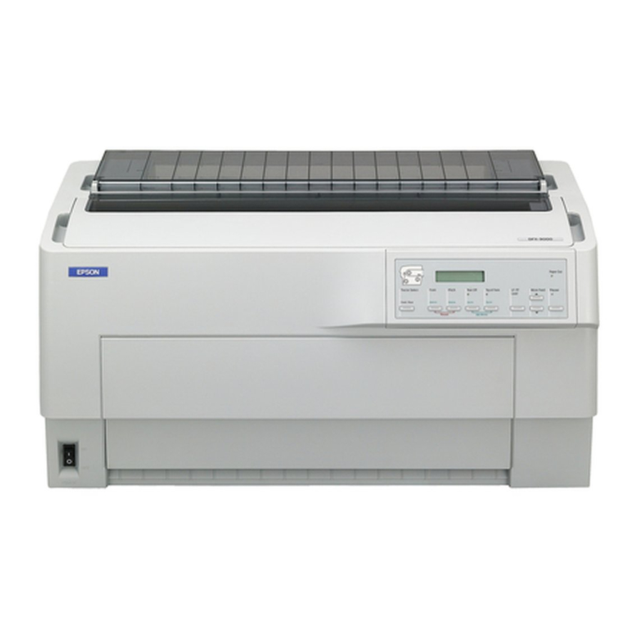
Page 60: Dimensions And Weight
Epson DFX-9000 Revision B 1.4 Dimensions and weight Physical specifications Dimensions: 700 mm (W) × 378 mm (D) × 363 mm (H) 27.5 inches × 14.9 inches × 14.3 inches Weight: 34 kg / 75 lbs Appearance: See the figure below. - Page 61 Epson DFX-9000 Revision B Product Description Dimensions and weight...
- Page 62 C H A P T E R OPERATING PRINCIPLES...
-
Page 63: Overview
Epson DFX-9000 Revision B 2.1 Overview The main components for removal and repair are: Power Unit OP Board ROM board: Control board Power unit: Power supply board OP board: Operation panel board Printer mechanism: Print Head Carrier mechanism ROM Board... -
Page 64: Part Names
Epson DFX-9000 Revision B 2.1.1 Part names Table 2-1. Part name definitions (continued) Traditional Some of the part names used in the DFX-9000 differ from part names DFX-9000 Definition Epson traditionally used in Epson printers. The table below provides part name... -
Page 65: Printer Mechanism
Epson DFX-9000 Revision B 2.2 Printer mechanism 2.2.1 Printhead The printhead contains 36 coils that drive armatures to which the print The operating principles of the printer mechanism are described below, wires are attached. and includes the following sections: When not firing, the armatures are pushed back to the stopper by coil 2.2.1 Printhead (p.58) - Page 66 Epson DFX-9000 Revision B 2.2.1.1 Printhead pinout Pin Group Each Pin Group The printhead is comprised of four 9-pin heads. The four heads are consists of 9 pins arranged in two head pairs, Front and Rear. Head numbers 3 and 4...
- Page 67 Epson DFX-9000 Revision B 2.2.1.2 Pin assignment for printing Table 2-2. Thermal sensor and print operation control Thermistor The printhead drive circuit is equipped with a print data register that has Temperature Printing operation resistance data capacity for 9 pins × 69 columns. The print data register controls 114 °C...
-
Page 68: Carrier Drive Mechanism
Epson DFX-9000 Revision B 2.2.2 Carrier drive mechanism CES Scale Carrier Shaft The Carrier unit is attached to the SP (CR) belt, which has a driven pulley on one end and an idle pulley on the other. Drive force is... - Page 69 Epson DFX-9000 Revision B 2.2.2.1 Carrier mechanism error detection 2.2.2.2 SP motor thermal protection control (with built-in thermistor) There are two error detection methods for the Carrier drive mechanism: To prevent the SP motor from burning out, if the SP motor temperature...
-
Page 70: Ribbon Drive Mechanism
Epson DFX-9000 Revision B 2.2.3 Ribbon drive mechanism The drive force from the Ribbon Feed (RF) motor is transmitted via the Bevel Gear, Gear, and the RF Gear. The RF Gear is directly linked to the RF Shaft, which rotates the ribbon. The RF Shaft rotates in one direction Bevel Gear only, regardless of which direction (right or left) the Carrier unit moves. -
Page 71: Paper Feed Mechanism
Epson DFX-9000 Revision B 2.2.4 Paper feed mechanism Tension Pulley DV Gear R1 2.2.4.1 Tractor mechanism Nip Gear F DV Roller R DV Roller F The Line Feed (LF) motor drive system is a unipolar, constant current DV Gear F drive. - Page 72 Epson DFX-9000 Revision B Continuous form feeding 1st Nip Card Roller Guide Continuous forms are fed by a pair of Pin belt tractors attached to the left Paper Eject and right ends of the Tractor shaft (square shaft). A continuous form fed...
-
Page 73: Paper Detection
Epson DFX-9000 Revision B 2.2.4.2 Paper detection Paper is detected by sensor levers located on the tractors, and reflective Sensor Lever sensors on the Card guide and Paper eject unit. Paper sensor The photo sensors on the tractors are shielded or unshielded by the movement of the sensor-lever. - Page 74 Epson DFX-9000 Revision B Top of form sensor Reflective TOFS Sensor The reflective Top of Form sensor (TOFS) attached to the Card guide Reflective TPES Sensor Card Guide detects the presence of paper by receiving light reflected from paper. Carrier Unit The sensor also detects line feed position, i.e.
-
Page 75: Auto Paper Feed
Epson DFX-9000 Revision B 2.2.4.3 Auto paper feed Tractor feed mechanism error detection Once set onto the tractors, paper is loaded into the mechanism using the An error in the tractor feed mechanism is detected by the PF driver control panel. Press the [LL/LF Load] button and the carriage moves to... - Page 76 Epson DFX-9000 Revision B path switching mechanism 2.2.4.4 Paper Paper path switching mechanism error detection The switch between front-feed and rear-feed is made automatically by Paper path switching mechanism errors are detected by the HCPP motor the Host-computer Control Paper Path (HCPP) motor drive. The drive driver.
-
Page 77: Paper Eject Mechanism
Epson DFX-9000 Revision B 2.2.4.5 Paper eject mechanism Paper eject operation mode Condition Roller 1 DV Roller R Status The DV roller R and the Nip roller in the Paper eject unit operate to prevent line feeding errors. The drive force of the Open/Close (OC) - Page 78 Epson DFX-9000 Revision B Paper eject mechanism error detection An error in the paper eject mechanism can be detected by the Open/ Close (OC) motor driver. The error ( ) is Fatal error: OC driver error detected when a single phase of the OC motor is energized for longer than the allowed period of time.
-
Page 79: Automatic Paper Thickness Control (Aptc) Mechanism
Epson DFX-9000 Revision B 2.2.5 Automatic Paper Thickness Control (APTC) mechanism The Automatic Paper Thickness control (APTC) mechanism includes Carrier Shaft the APTC unit, Carrier shaft, and the Guide stay. Carrier Unit The Carrier transports the Printhead, and travels horizontally along the Carrier Shaft and Guide Stay. - Page 80 Motor while monitoring the width of (time between) the pulses output Figure 2-15 shows the components of the DFX-9000 platen-gap from the APTC Sensor-encoder. A change in encoder pulse width is measurement. As illustrated, the platen-gap is divided into two sections: interpreted as an increase of the APTC Motor load due to the printhead the Media-gap and the Paper thickness.
-
Page 81: Error Detection
Epson DFX-9000 Revision B The relationship between paper thickness and the platen gap is shown in Platen gap adjustment sequence the table below: Table 2-4. Paper thickness and platen gap Paper Thickness (mm) Print Panel Move the printhead to the... -
Page 82: Other Mechanisms
Epson DFX-9000 Revision B 2.2.6 Other mechanisms Top Cover Actuators 2.2.6.1 Top cover open/close detection mechanism INLK SW ASY When the top cover is opened, two switches open causing the SP motor and printing to stop. The Cover Open Switch assembly (CO SW ASY) -
Page 83: Cooling Fans
Epson DFX-9000 Revision B 2.2.6.2 Cooling fans The four fans, 1 on the left side frame and 3 on the right side frame, FAN4 Motor prevent the inside temperature of the printer from rising too high. Each of the fan motors has a rotation detection sensor that outputs a pulse signal. -
Page 84: Circuit Operation
Epson DFX-9000 Revision B 2.3 Circuit operation ROM Board The printer includes the following circuits. Interface Table 2-6. DFX-9000 Circuit Boards Board Function SP Motor ROM Board Main control circuit Parallel Interface 3.3 V voltage generation/ retention circuit INLK SW ASY... -
Page 85: Rom Board
Epson DFX-9000 Revision B 2.3.1 ROM board OP Board The ROM board is a main controller of this printer and is divided into Power Unit (LCD/LED/SW) Parallel Interface the following two circuits: Serial Interface USB Interface Type-B Interface Logic Control circuit... - Page 86 Epson DFX-9000 Revision B Table 2-7. Major IC elements SoC ASIC Location Name Function (summary) The SoC (System on Chip) ASIC is a one-chip custom gate array, LSI1 SiX55513 ASIC coupled with CPU consisting of a 32-bit RISC CPU, associated standard peripheral control...
- Page 87 Epson DFX-9000 Revision B The table below shows the dot-matrix-printer-specific circuit modules Table 2-8. SoC ASIC functional modules (continued) on the SoC ASIC Module Description TIMER_PRES 8-bit timer pre-scaler. Table 2-8. SoC ASIC functional modules (used for generating a reference clock for the...
- Page 88 Epson DFX-9000 Revision B Memory circuit control As shown in the figure below, the memory circuit consists of three XWRL memory devices: Flash memory, D-RAM, and F-RAM. Brief SoC ASIC Flash Memory (LSI1) (IC1) descriptions for each memory device are given below.
- Page 89 Epson DFX-9000 Revision B 2.3.1.2 Mechanism control circuit Motor Drive control circuits The Mechanism Control circuit is managed by the Mechanism Control This printer has six circuits for driving the six motors: SP (Space or CR) ASIC, and the figure below is the internal block diagram of this ASIC.
- Page 90 Epson DFX-9000 Revision B M_BRAKE is a brake input signal. When the signal is low, the SP Motor drive circuit motor is braked. When the signal is high, the motor rotates normally. The SP motor is a DC brushless motor. A dedicated brushless motor PWMIN is a pulse input signal (M_TIM1), and its output is control IC is used to control the speed and position.
- Page 91 Epson DFX-9000 Revision B performed between the LF motor driver internal comparing circuit and LF Motor drive circuit the phase data signal to turn the internal FET OFF, keeping the output The LF Motor is a HB stepping motor. A dedicated unipolar drive current constant.
- Page 92 Epson DFX-9000 Revision B RF Motor drive circuit HCPP Motor, APTC Motor, and OC Motor Drive Circuits The RF motor is a permanent magnet (PM) stepping motor. A dedicated The HCPP motor, APTC motor, and OC motor are PM stepping motors.
- Page 93 Epson DFX-9000 Revision B Perforation Cutter Drive Circuit Motor Malfunction Detection The Perforation cutter motor is controlled by the output of the PHASE Each motor drive circuit is equipped with the overcurrent detection and ENABLE signals from the Mechanism Control ASIC. The function.
-
Page 94: Printhead Control
Epson DFX-9000 Revision B Printhead control Printhead Control Circuit The printhead control circuitry includes the print data extraction section, The following shows a block diagram of the printhead control circuit. main excitation / flyback time selection section, print trigger generation section, and the print timing control section. - Page 95 Epson DFX-9000 Revision B Main excitation / flyback time selection circuitry Printhead timing control This section utilizes an 8-bit Analog/Digital converter to monitor the After the required offset time is set on a print trigger basis, the main and head drive voltage (42 V), the 16-byte front main excitation time table, flyback pulses are generated based on the input from the main front flyback time table, and rear flyback time table.
-
Page 96: Product Description
Epson DFX-9000 Revision B 2.3.2 OP board The offset time is the sum of the following four offset values. Offset time = Speed offset + FR offset + constant offset + flight time The LCD, LED and operation buttons are mounted on the OP (Operator offset Panel) board. -
Page 97: Power Supply Circuit
Epson DFX-9000 Revision B 2.3.3 Power supply circuit +5V converter section This section consists of a ringing choke converter and has the The power supply circuit consists of the following sections. following functions. Overcurrent control Input noise filter If the +5 V load somehow becomes shorted, the +5 V output is... - Page 98 Epson DFX-9000 Revision B Overcurrent control The voltage switching timing is shown below. If the +37 V load somehow becomes shorted, the +37 V output is drooped automatically to prevent the power supply from being damaged. Overvoltage control POW_OFF If an overvoltage occurs on the +37 V output due to a...
- Page 99 Epson DFX-9000 Revision B Operating Principles Circuit operation...
- Page 100 C H A P T E R TROUBLESHOOTING...
-
Page 101: Overview
Before starting disassembly and assembly work, read and C A U T I O N understand thoroughly the contents of 3.1.2 Preliminary In addition, the User's Manual for the EPSON DFX-9000 describes checks (p.95). detailed steps to be taken for recovery from typical user errors. -
Page 102: Preliminary Checks
Epson DFX 9000 Revision B 3.1.2 Preliminary checks 13. If you cannot print data from the host computer, initiate the printer’s self test and check for problems with the output. Check the Default Before starting troubleshooting, be sure to verify that the following Settings printed on the Self Test for any incorrect settings. -
Page 103: Power-On Initialization Sequence
Epson DFX 9000 Revision B 3.1.3 Power-on initialization sequence Main Troubleshooting Overview... - Page 104 Epson DFX 9000 Revision B Mechanism initialization Troubleshooting Overview...
- Page 105 Epson DFX 9000 Revision B Mechanism initialization, continued Troubleshooting Overview...
- Page 106 Epson DFX 9000 Revision B Paper Backout RTN from TOF Mark Position Paper Ejection RTN from Tear-Off state Troubleshooting Overview...
- Page 107 Epson DFX 9000 Revision B (FF) APER EEDING APG A PPROACH Troubleshooting Overview...
-
Page 108: Error And Warning Messages
Epson DFX 9000 Revision B 3.2 Error and warning messages Table 3-1. List of General Error Beeper sounds LCD Message Status Remedy Paper Tear (see Pause Front Rear below) Form Blink Head hot warning. The Wait for the temperature of the head... - Page 109 Epson DFX 9000 Revision B Table 3-1. List of General Error Beeper sounds LCD Message Status Remedy Paper Tear (see Pause Front Rear below) Form Error: Cover Cover open error: The printer Close the top cover. • • • open top cover is open.
-
Page 110: Fatal Errors
Epson DFX 9000 Revision B 3.2.1 Fatal errors Table 3-2. List of Fatal Errors Fatal Error Description Reference 3.2.1.1 List of fatal errors Code Table 3-2. List of Fatal Errors HCPP Error Page 110 Fatal OC Driver Error Page 110... -
Page 111: Troubleshooting
Epson DFX 9000 Revision B 3.3 Troubleshooting 3.3.1.2 Sensor and switch reference Table 3-4. Sensors and switches test reference 3.3.1 Test reference values Sensor Type Logical state FTRPE Photo-interrupt Low = paper present 3.3.1.1 Motor test reference RTRPE Photo-interrupt Low = paper present The table below lists the resistance values for the motors on the printer. - Page 112 Epson DFX 9000 Revision B 3.3.1.3 Printhead coil resistance values Head coil resistance is 4.1 ~ 4.9 ohm at 20 °C. Table 3-5. Printhead - Contact pin assignment Contact (lead) Front PCB Front PCB Rear PCB Rear PCB number side A...
-
Page 113: Troubleshooting Based On Error Codes
Epson DFX 9000 Revision B 3.3.2 Troubleshooting based on error codes Fatal Error Code 02: CR Driver Error This section describes troubleshooting based on the error codes that are The SP motor or driver circuit (IC18) is malfunctioning. displayed when a fatal error occurs. - Page 114 Epson DFX 9000 Revision B This error indicates a power output problem, or a voltage detection Fatal Error Code 04: PF Driver Error circuit failure. The Mechanism Control ASIC detected either: Check and replace the following in the order below, checking Abnormal current to the LF motor functionality at each step.
- Page 115 Epson DFX 9000 Revision B Check the following in the order below, testing functionality at each Fatal Error Code 09: FAN1 Driver Error step. 0A: FAN2 Driver Error 0B: FAN3 Driver Error 1. Check that the PRINT HEAD (p.152) is installed correctly.
- Page 116 Epson DFX 9000 Revision B Check for a ribbon jam, and replace the ribbon cartridge if necessary. If Fatal Error Code 0F: APTC Error the ribbon cartridge is not jammed, this error may be the result of a This error occurs when the Home Position (HP) of the Automatic Paper malfunction of the RF sensor circuit, RF motor or RF motor driver Thickness Control (APTC) mechanism is not detected.
- Page 117 Epson DFX 9000 Revision B Fatal Error Code 13: HCPP Driver Error Fatal Error Code 15: OC Driver Error This error occurs when the Mechanism Control ASIC detects that a This error occurs when the Mechanism Control ASIC detects that a...
- Page 118 Epson DFX 9000 Revision B Fatal Error Code 17: PC Driver Error Fatal Error Code 30: CG Error This error occurs when the Mechanism Control ASIC detects that a This error is caused by a memory circuit failure on the ROM Board.
-
Page 119: Troubleshooting Based On Symptoms
Epson DFX 9000 Revision B 3.3.3 Troubleshooting based on symptoms Table 3-6. Troubleshooting Based on Symptoms Symptom Status Reference This section describes the troubleshooting based on symptoms of the Printing-related The printer does not receive or does Page 115 printer. - Page 120 Epson DFX 9000 Revision B Table 3-6. Troubleshooting Based on Symptoms Symptom Status Reference Paper feed- The printer does not feed continuous Page 119 related trouble forms from the Front or Rear. The Paper Path does not switch Page 119 properly.
- Page 121 Epson DFX 9000 Revision B The printer does not initialize when the power is Troubleshooting procedure turned on None of the Power source problem. 1. Check the power cable connection at both ends. Perform a continuity check on Control Panel the cable.
- Page 122 Epson DFX 9000 Revision B Printing-related failure Troubleshooting procedure The printer does The printer does not print at all. Perform the following and check functionality after each step. not receive or does 1. Check that the data interface cable is functional and connected correctly to the not print data sent printer and host computer.
- Page 123 Epson DFX 9000 Revision B Printing-related failure Troubleshooting procedure Some dots are missing, or unnecessary dots are printed. Perform the following, checking for functionality after each step. (NOTE: If the printed characters are uneven on their upper or 1. Clean or Replace the CES SCALE (p.159).
- Page 124 Epson DFX 9000 Revision B Printing-related failure Troubleshooting procedure The printout appears dirty, or there is ribbon ink or 1. Verify that the ribbon cartridge is correctly installed. contamination on the printout. 2. Check that the ribbon is in good condition: no excessive wear, has not frayed, or come unravelled.
- Page 125 Epson DFX 9000 Revision B Ribbon-related failure Troubleshooting procedure The printout is partially printed white or the ribbon is 1. Reinstall or replace the ribbon cassette. disengaged. 2. The ribbon may bind, bend or reverse if the CARD GUIDE ASY is not adjusted The ribbon has excess slack.
-
Page 126: The Paper Feed Position Is Incorrect
Epson DFX 9000 Revision B Paper feed related failure Troubleshooting procedure The printer does not feed continuous forms from the 1. Check and replace the LF MOTOR (p.161). Front or Rear. 2. Check and replace the ROM BOARD (p.137). The Paper Path does not switch properly. -
Page 127: Paper Is Not Fed Or Ejected Properly
Epson DFX 9000 Revision B Paper feed related failure Troubleshooting procedure Paper is not fed or ejected properly. 1. Perform the TOF sensor sensitivity adjustment (p.235), or replace the TOF Sensor - part of the CARD GUIDE ASY (p.153). 2. Check the TPE (Top Paper Empty) Sensor, and its connection to CNTPE on the Sensor Board. -
Page 128: Paper Jams Occur During Paper Feed
Epson DFX 9000 Revision B Paper feed related failure Troubleshooting procedure Paper jams occur during paper feed. 1. Verify that the paper is within all Paper specifications (p.13), and make sure the paper is mounted correctly and evenly in the tractors. - Page 129 Epson DFX 9000 Revision B Control Panel related failure Troubleshooting procedure The switches on the control panel are inoperable. 1. Check whether the printer has been Paused, and if so place the printer online. 2. Verify the OP CABLE connection between the OP Board and ROM BOARD.
-
Page 130: Disassembly And Assembly
C H A P T E R DISASSEMBLY AND ASSEMBLY... -
Page 131: Overview
This section describes procedures for disassembling and assembling the Use only the recommended tools for maintenance work. Epson DFX 9000. Unless otherwise specified, disassembled units or components can be re-assembled by reversing the disassembly Use only the recommended lubricants and adhesives. -
Page 132: Tools And Instruments
Epson DFX 9000 Revision B 4.1.2 Tools and instruments The table below lists the tools and the instruments required for disassembling, assembling or adjusting the printer. Use only tools that meet these specifications. Table 4-1. Tool and Instrument List Name Specification Epson Part No. -
Page 133: Abbreviations For Small Parts
Epson DFX 9000 Revision B 4.1.3 Abbreviations for small parts Table 4-2. List of Screws Used Name and specification Image The table below lists the abbreviations used in this manual for small parts, such as screws and washers. C.P. (M3 × 6) Table 4-2. -
Page 134: Service Check After Repair
Epson DFX 9000 Revision B 4.1.4 Service check after repair After you repair the product, use the check list below to check and record the status of the repaired product before returning the product to the user. This list can be used as a record of all service work performed with the product. - Page 135 Epson DFX 9000 Revision B Table 4-3. Repair Status Check List (continued) Category Component Item to Check Status Printer Ribbon Mask Is the ribbon mask free of damage? Checked, OK Mechanism Not necessary Operation Self-Test Was the self-test print successful?
-
Page 136: Main Components Disassembly
Epson DFX 9000 Revision B 4.2 Main components disassembly This section provides the disassembly procedures. The basic order for disassembly is shown in the flowchart below. The exploded diagrams, provided in the Appendix, “Exploded diagrams” (page 318), are helpful to see how components are engaged with each other. -
Page 137: Major Component Replacement Flowcharts
Epson DFX 9000 Revision B 4.2.1 Major component replacement flowcharts PRINT HEAD (p. 152) CARD GUIDE ASY (p. 153) PR MECHA ASY (p. 149) START START FRONT COVER ASY (p. 132) PRINT HEAD (p. 152) FRONT COVER ASY (p. 132) REAR UNIT (p. - Page 138 Epson DFX 9000 Revision B Sensors (p. 195) CARRIER UNIT (p. 191) START START FRONT COVER ASY (p.132) REAR UNIT (p.133) FRONT COVER ASY (p.132) REAR UNIT (p.133) PRINT HEAD (p.152) OP UNIT (p.134) OP UNIT (p.134) UPPER UNIT (p.135) UPPER UNIT (p.135)
-
Page 139: Covers
Epson DFX 9000 Revision B 4.2.2 Covers 2. With the FRONT COVER ASY open, push it to the right until the center bows upward enough to release it from the hinge pin on the left side of the UPPER UNIT. -
Page 140: Interface Cover
Epson DFX 9000 Revision B 4.2.2.2 INTERFACE COVER 4.2.2.3 REAR UNIT 1. Facing the rear of the printer, release the two tabs that secure the 1. Open the REAR UNIT and remove the four screws (two on either INTERFACE COVER to the REAR UNIT, and open the side) that secure it to the printer. -
Page 141: Op Unit
Epson DFX 9000 Revision B 4.2.2.4 OP UNIT 1. Open the TOP COVER, and release the three tabs on the inside top edge of the OP UNIT by pressing them from inside the UPPER UNIT. Gently pull the OP UNIT out toward you to gain access to the OP CABLE. -
Page 142: Upper Unit
Epson DFX 9000 Revision B 4.2.2.5 UPPER UNIT 7. Remove the two C.B.P. 3 × 8 screws, one on each side, that secure the TOP COVER rotation stops to the inside of the UPPER UNIT. 1. Remove the FRONT COVER ASY (p. 132) 2. -
Page 143: Electrical Circuit Board Removal
Epson DFX 9000 Revision B 4.2.3 Electrical circuit board removal 5. Lift the rear of the POWER UNIT slightly, and slide it rearward in the direction of the arrow. Release the two tabs that secure the front of the POWER UNIT as you lift it by the rear and remove it. - Page 144 Epson DFX 9000 Revision B 4.2.3.2 ROM BOARD Be careful with the edges of the shield plate, as they are W A R N I N G very sharp. When replacing the ROM BOARD, be sure to first try to...
- Page 145 Epson DFX 9000 Revision B 6. Remove the two C.B.S. 3 × 6 screws that secure the Guide plate, Guide plate slide it back from the Interface Plate, and remove the Guide plate upward. 7. Release the two tabs that secure the Guide rail to the ROM BOARD,...
-
Page 146: Sensor Board Unit
Epson DFX 9000 Revision B 4.2.3.3 SENSOR BOARD UNIT Disconnect the power cable and wait at least 5 minutes for W A R N I N G capacitors to drain before disassembling the POWER UNIT. If you touch the POWER UNIT with the power supplied, you may receive an electric shock. - Page 147 Epson DFX 9000 Revision B Table 4-4. SENSOR BOARD connector definitions Connector Name Pins Color Connects to CNO/C White OC MOTOR CNHCPP Black HCPP MOTOR Cable M CNAPTC APTC MOTOR CNRB White RF MOTOR Ferrite Core CNFAN1 White FAN1 MOTOR...
- Page 148 Epson DFX 9000 Revision B 3. Pinch the locking tabs on the four L-Cap spacers that secure the L-Cap spacer SENSOR BOARD UNIT to the bottom rear of the printer, and remove the SENSOR BOARD UNIT. Do not install the SENSOR BOARD UNIT upside down or reversed.
- Page 149 Epson DFX 9000 Revision B 4.2.3.4 AC SW ASY, INLET ASY Blue cable Disconnect the power cable and wait at least 5 minutes for INLET ASY W A R N I N G capacitors to drain before disassembling the POWER UNIT.
- Page 150 Epson DFX 9000 Revision B 5. Remove the AC SW ASY by pushing it out from inside the LOWER UNIT while pressing down the upper locking tab. 6. Pull the AC SW ASY cables out of the LOWER UNIT. To fit the cables through the switch hole, first pull the Blue...
- Page 151 Epson DFX 9000 Revision B 4.2.3.5 OP CABLE Disconnect the power cable and wait at least 5 minutes for W A R N I N G capacitors to drain before disassembling the POWER Cable clamp UNIT. If you touch the POWER UNIT with the power 4)-1 supplied, you may receive an electric shock.
- Page 152 Epson DFX 9000 Revision B 4.2.3.6 PSU1 CABLE Disconnect the power cable and wait at least 5 minutes for W A R N I N G POWER capacitors to drain before disassembling the POWER BOARD UNIT Side Side UNIT. If you touch the POWER UNIT with the power supplied, you may receive an electric shock.
- Page 153 Epson DFX 9000 Revision B 4.2.3.7 Safety switches INLK SW ASY Disconnect the power cable and wait at least 5 minutes W A R N I N G for capacitors to drain before disassembling the INLK SW ASY 5)-2 POWER UNIT. If you touch the POWER UNIT with the power supplied, you may receive an electric shock.
- Page 154 Epson DFX 9000 Revision B CO SW ASY Disconnect the power cable and wait at least 5 minutes W A R N I N G for capacitors to drain before disassembling the POWER UNIT. If you touch the POWER UNIT with the power supplied, you may receive an electric shock.
- Page 155 Epson DFX 9000 Revision B Replacing INLK SW ASY / CO SW ASY INLK SW ASY The plastic gutter is attached to both the INLK SW ASY C H E C K P O I N T and the CO SW ASY, as shown in Figure 4-22.
-
Page 156: Printer Mechanism
Epson DFX 9000 Revision B 4.2.4 Printer mechanism Lift handles (rear and front) OP CABLE 4.2.4.1 PR MECHA ASY Do not touch the motors immediately after using the W A R N I N G 2)-1 printer, or you may burn your hand. Allow the motors to cool enough to work with them. - Page 157 Epson DFX 9000 Revision B 4. Disconnect the cables shown in Figure 4-24 from the ROM CNSPHS CNRHD1 CNRHD2 CNFHD1 BOARD. CNFHD2 Connector Pins Color Connects to / Function CNHD3 CNRHD1 White Carrier PCB (Front PRINT HEAD L, R) CNRHD2...
-
Page 158: Adjustment
Epson DFX 9000 Revision B The following adjustments are required after replacing the A D J U S T M E N T R E Q U I R E D PR MECHA ASSY. APTC thickness detection adjustment (p. 238) APTC detection position adjustment (p. - Page 159 Epson DFX 9000 Revision B 4.2.4.2 PRINT HEAD Positioning pin insertion positions PRINTHEAD Do not touch the PRINT HEAD immediately after using W A R N I N G the printer, or you may burn your hand. Allow the head to cool enough to work with it.
-
Page 160: Card Guide Asy
Epson DFX 9000 Revision B 4.2.4.3 CARD GUIDE ASY CARD GUIDE ASY 1. Remove the UPPER UNIT (p. 135) 6)-1 C.P. (S-P1) TOF sensor cable 2. Remove the PRINT HEAD (p. 152) 6)-1 3. Remove the two C.P. (S-P1) 2.5 × 8 and one C.F. 2.5 × 6 screws that... -
Page 161: Adjustment
Epson DFX 9000 Revision B When installing the Carrier holder, replace the cable protector correctly in the CARRIER UNIT. See Figure CARD GUIDE ASY 4-27. When installing the CARD GUIDE ASY, thread the TOF sensor cables as shown in Figure 4-28. - Page 162 Epson DFX 9000 Revision B Ribbon MASK 1. Remove the PRINT HEAD (p. 152) 2. Slowly bow toward you the left end of the Ribbon MASK as shown Guide slot Figure 4-29. Release the Mask from the guide slot and pin that secure the MASK to the left side of the CARD GUIDE ASY.
-
Page 163: Sp Motor Asy
Epson DFX 9000 Revision B 4.2.4.4 SP MOTOR ASY Do not touch the SP MOTOR ASY immediately after W A R N I N G SP MOTOR ASY using the printer, or you may burn your hand. Allow the motor assembly to cool enough to work with it. - Page 164 Epson DFX 9000 Revision B 8. Tilt the rear of the SP MOTOR ASY to the right, and lift the Tension pulley to remove the SP MOTOR ASY together with the SP BELT. When you remove the Tension pulley, be careful not to...
-
Page 165: Adjustment
Epson DFX 9000 Revision B 4.2.4.5 SP BELT CARRIER CABLE UNIT The Carrier PCB and a ferrite core is attached are attached C A U T I O N CARRIER UNIT to the CARRIER UNIT. Handle them with care when removing or replacing the SP BELT. -
Page 166: Ces Scale
Epson DFX 9000 Revision B 4.2.4.6 CES SCALE Do not touch the PRINT HEAD immediately after using W A R N I N G the printer, or you may burn your hand. Allow the head to cool enough to work with it. - Page 167 Epson DFX 9000 Revision B 4. Remove the C.B.S. 3 × 6 screw that secures the left end of the CES SCALE to the inside of the SIDE FRAME, LEFT, and slowly pull Reassembly the CES SCALE out from the CES sensor on the bottom of the mark CARRIER UNIT.
-
Page 168: Lf Motor
Epson DFX 9000 Revision B 4.2.4.7 LF MOTOR Do not touch the LF MOTOR immediately after using the W A R N I N G printer, or you may burn your hand. Allow the motor to cool enough to work with it. - Page 169 Epson DFX 9000 Revision B 4.2.4.8 LF BELT 1. Remove the UPPER UNIT (p. 135) 2. Tilt up the rear of the PR MECHA ASY and support it using the tilt bar. Refer to section 4.2.4.1 PR MECHA ASY, p. 149.
-
Page 170: Rf Motor
Epson DFX 9000 Revision B 4.2.4.9 RF MOTOR Cable clamp Do not touch the RF MOTOR immediately after using the W A R N I N G printer, or you may burn your hand. Allow the motor to cool enough to work with it. -
Page 171: Rf Unit
Epson DFX 9000 Revision B 4.2.4.10 RF UNIT Do not touch the RF MOTOR immediately after using the W A R N I N G printer, or you may burn your hand. Allow the motor to cool enough to work with it. - Page 172 Epson DFX 9000 Revision B 6. Remove the C.B.S. 3 × 6 screw that secures the RF UNIT to the SIDE FRAME, RIGHT, and remove the RF UNIT while slowly feeding the cables through the SIDE FRAME, RIGHT. The connectors on the end of the cables will fit through the hole one-at-a-time.
-
Page 173: Oc Motor
Epson DFX 9000 Revision B 4.2.4.11 OC MOTOR Be sure to lubricate the OC gear and stud after removing or A D J U S T M E N T R E Q U I R E D replacing the OC MOTOR. See Figure 6-3. - Page 174 Epson DFX 9000 Revision B 6)-1 6)-1 Front 6)-2 Gear OC MOTOR [Front] 4)-1 CNO/C [Rear] SENSOR BOARD UNIT Figure 4-46. OC MOTOR Removal Disassembly and Assembly OC MOTOR...
-
Page 175: Hcpp Motor
Epson DFX 9000 Revision B 4.2.4.12 HCPP MOTOR Do not touch the HCPP MOTOR immediately after using W A R N I N G the printer, or you may burn your hand. Allow the motor to cool enough to work with it. -
Page 176: Adjustment
Epson DFX 9000 Revision B 4.2.4.13 APTC UNIT Dowel 1. Remove the UPPER UNIT (p. 135) 7)-1 2. Tilt up the rear of the PR MECHA ASY and support it using the tilt bar. (Refer to section 4.2.4.1 PR MECHA ASY, p. - Page 177 Epson DFX 9000 Revision B 4.2.4.14 TRACTOR UNIT Reassembly Tractor Shaft [Front] SENSOR BOARD UNIT Cable TRACTOR FL UNIT/TRACTOR FR UNIT Clamp 1. Remove the PR MECHA ASY (p. 149) 2. Position the Tractor locks of both the TRACTOR FL UNIT and TRACTOR FR UNIT at “FREE”.
-
Page 178: Adjustment
Epson DFX 9000 Revision B Secure the FTRPE sensor cable with the cable clamps, Reassembly (A) Spring washer Spring washer making length adjustments to meet the following Tractor Shaft conditions: Too much tension should not be applied to the cable when moving the TRACTOR FL UNIT to the right. -
Page 179: Adjustment
Epson DFX 9000 Revision B TRACTOR RL UNIT/TRACTOR RR UNIT [Front] RTRPE Sensor Cable SENSOR BOARD UNIT 1. Remove the PR MECHA ASY (p. 149) 2. Remove the SP MOTOR ASY (p. 156) 3. Remove the FAN3 MOTOR. See FAN MOTORS (FAN1 MOTOR to FAN4 MOTOR) (p. -
Page 180: Adjustment
Epson DFX 9000 Revision B 8. Remove the OC Slide Cam L. See 4.2.4.15 DV ROLLER UNIT (p.175). Pulley Gear TR Gear 2 9. Remove the E-ring that secures the Pulley Gear to the SIDE Bearings FRAME, LEFT, and remove the Pulley Gear. - Page 181 Epson DFX 9000 Revision B When reassembling the rear tractor assembly (TRACTOR RL UNIT, TRACTOR RR UNIT) and installing it to the printer mechanism, be sure to assemble whole parts; the springs and the guide wheels, to the Sub shaft, as shown in Figure 4-53.
- Page 182 Epson DFX 9000 Revision B 4.2.4.15 DV ROLLER UNIT DV ROLLER R ASY DV ROLLER F ASY 6)-3 DV gear 6)-2 1. Remove the PR MECHA ASY (p. 149) Belt guide 2. Remove the TPE HOLDER ASY (p. 201) 6)-1 E-ring 3.
- Page 183 Epson DFX 9000 Revision B 8. Remove the C.B.S. 3 × 6 screw that secures the OC SENSOR BR 11)-2 UNIT, and remove the OC SENSOR UNIT. (OC SENSOR BR OC cam OC SENSOR BR UNIT Nip roller shaft UNIT (p.
- Page 184 Epson DFX 9000 Revision B 13. Remove the two C.B.S. 3 × 6 screws that secure the Nip bracket unit to the SIDE FRAME, RIGHT, and remove the Nip bracket unit. 14)-1 DV gear R 14. Release the two tabs that secure the DV gear R to the right end of the DV ROLLER R ASY, and remove the DV gear R, spring washer, and washer.
- Page 185 Epson DFX 9000 Revision B 17. Remove the two C.B.S. 3 × 6 screws that secure the Lower guide F Right side Left side ASY to the SIDE FRAME, LEFT / RIGHT. Remove only the two screws without removing the Lower...
-
Page 186: Adjustment
Epson DFX 9000 Revision B The OC slide cam L and OC cam, and the OC slide cam R and OC cam have phases that must be matched. Refer to the figure below and install these parts so that the center of the phase mark on the OC cam aligns with the window in the Left and Right OC slide cam, respectively. - Page 187 Epson DFX 9000 Revision B DV ROLLER R ASY DV ROLLER R ASY 1. Remove the PR MECHA ASY (p. 149) 6)-3 2. Remove the TPE HOLDER ASY (p. 201) DV gear 6)-2 Belt guide 3. Remove the four screws that secure the Back stay ASY, and remove 6)-1 the PTRM SWITCH ASY together with the Back stay ASY.
- Page 188 Epson DFX 9000 Revision B 8. Remove the C.B.S. 3 × 6 screw that secures the OC SENSOR BR 11)-2 UNIT, and remove the OC SENSOR BR UNIT. See OC SENSOR Bearing RL OC SENSOR BR UNIT DV ROLLER R ASY BR UNIT (p.
- Page 189 Epson DFX 9000 Revision B 12. Remove the E-ring that secures the left end of the OC shaft, and remove the OC gear 1, spring washer, washer, and the OC Bearing L. 13. Remove the E-ring that secures the left end of the Nip roller shaft R, and remove the Collar.
- Page 190 Epson DFX 9000 Revision B 14. Remove the two C.B.S. 3 × 6 screws that secure the Nip bracket unit to the SIDE FRAME, RIGHT, and remove the Nip bracket unit. 15)-1 DV gear R 15. Release the tab that secures the DV gear R to the right end of the DV ROLLER R ASY, and remove the DV gear R, spring washer, and washer.
- Page 191 Epson DFX 9000 Revision B 18. Remove the E-ring that secures the right end of the Nip roller shaft R, and remove the Nip gear R2. 20)-2 OC gear1 20)-3 OC shaft 19. Remove the E-ring that secures the Collar to the Nip roller shaft R,...
- Page 192 Epson DFX 9000 Revision B 21. From inside the frame, remove the E-ring that secures the left end of Left side Right side the OC shaft to the inside of the Upper guide R unit. 23) Upper guide R spring 23) Upper guide L spring 22.
- Page 193 Epson DFX 9000 Revision B 24. Slide the OC shaft and Nip roller shaft R to the right until they clear the shaft holes on the SIDE FRAME, LEFT. 25. Lift up the left end of the Upper guide R unit to release it from the...
- Page 194 Epson DFX 9000 Revision B 26. Remove the four C.B.S. 3 × 6 screws that secure the Lower guide R, and remove it in the direction of the arrow in Figure 4-69. DV ROLLER R ASY 27)-2 27. Slide the DV ROLLER R ASY to the left to remove the right end of...
-
Page 195: Adjustment
Epson DFX 9000 Revision B The OC slide cam L and OC cam, and the OC slide cam R and OC cam have phases that must be matched. Refer to the figure below and install these parts so that the center of the phase mark on the OC cam is centered in the window in the left and right OC slide cams. - Page 196 Epson DFX 9000 Revision B 4.2.4.16 CARRIER CABLE UNIT Cable clamp Do not touch the motors or the PRINT HEAD immediately W A R N I N G after using the printer, or you may burn your hand. Allow them to cool enough to work with them.
- Page 197 Epson DFX 9000 Revision B 6. Slowly feed the CARRIER CABLE UNIT FFC inside the printer 9. Release the two tabs that secure the cable cover of the CARRIER mechanism toward the carrier as follows: First, pull the FFC from...
-
Page 198: Carrier Unit
Epson DFX 9000 Revision B 4.2.4.17 CARRIER UNIT When releasing the end of the Stay shaft from the SIDE C A U T I O N FRAME, RIGHT, pull the Stay shaft straight out without Stay shaft rotating it. Otherwise, the SS bearing may hit and damage the APTC HP sensor. - Page 199 Epson DFX 9000 Revision B 9. Hold both the SS bearing on the left end of the Stay shaft and the bearing on the right end, and slowly pull out the Stay shaft to the left rotating it until the right end of the Stay shaft nearly reaches the CARRIER UNIT.
- Page 200 Epson DFX 9000 Revision B CARRIER UNIT 11. Release all the cables from the two cable clamps on the SIDE Cable clamp FRAME, LEFT. 12. Remove the C.B.S. 3 × 6 screw that secures the CR cable cover, and remove the CR cable cover.
-
Page 201: Adjustment
Epson DFX 9000 Revision B 15. Slowly feed the CARRIER CABLE UNIT inward toward the Carrier Unit through the holes of the SIDE FRAME, RIGHT. (2 places) After removing or replacing the CARRIER UNIT, be sure A D J U S T M E N T R E Q U I R E D to perform the following maintenance and adjustments. - Page 202 Epson DFX 9000 Revision B 4.2.4.18 Sensors Screw the Nip shaft F securely with its flat-surfaces on both ends facing downward. PJS HOLDER ASY 1. Remove the PR MECHA ASY (p. 149) 2. Remove the Stay shaft. Refer to section 4.2.4.17 CARRIER UNIT, Nip Shaft F p.
- Page 203 Epson DFX 9000 Revision B [Front] SENSOR BOARD UNIT 4)-1 CNPJS 6)-1 6)-2 [Rear] [Front] Nip Shaft F VIEW FROM ABOVE THE PRINTER MECHANISM PJ sensor cable 4)-2 Figure 4-80. PJS HOLDER ASY Removal (1) Disassembly and Assembly Sensors...
- Page 204 Epson DFX 9000 Revision B 8. Remove the PJS HOLDER ASY from the PJS ROLLER. [Front] 9. Move the CARRIER UNIT to the right side of the PR MECHA Nip Shaft F ASY, and remove Nip shaft F together with the three Nip spring holders F, 3 Nip springs, PJS HOLDER ASY, and the PJS spring.
-
Page 205: Adjustment
Epson DFX 9000 Revision B 10. Slide the right-most Nip spring holder F and Nip spring F off of Nip shaft F. 11. Slide the PJS HOLDER ASY and the PJS spring off of Nip shaft F, and remove the PJS HOLDER ASY. - Page 206 Epson DFX 9000 Revision B PJS ROLLER Nip gear OC slide cam L 1. Remove the PJS HOLDER ASY (p. 195) DV gear LF BELT 2. Perform Steps 4 through 12 in DV ROLLER F ASY (p. 175), and remove the following parts from the SIDE FRAME, LEFT.
- Page 207 Epson DFX 9000 Revision B 3. Remove the E-rings on both ends of the Nip roller ASY. 4. Slide the Nip roller ASY to the left to clear the right-end of the shaft 5)-1 from the shaft hole, and then pull the left-end of the shaft from the Nip Roller F shaft hole to remove the Nip roller ASY.
- Page 208 Epson DFX 9000 Revision B TPE HOLDER ASY Disconnect the power cable and wait at least 5 minutes W A R N I N G for capacitors to drain before disassembling the POWER UNIT. If you touch the POWER UNIT with the power supplied, you may receive an electric shock.
- Page 209 Epson DFX 9000 Revision B 6. Release the TPE sensor cable from the retaining tab on the Upper guide R unit. TPE sensor Cable 7. Release the catch on the TPE HOLDER ASY, and tilt the TPE 7)-3 HOLDER ASY toward you. Pull the TPE sensor cable out from behind the Paper eject roller, and remove the TPE HOLDER ASY.
- Page 210 Epson DFX 9000 Revision B APTC HP UNIT [Front] SENSOR BOARD UNIT 4)-1 Disconnect the power cable and wait at least 5 minutes W A R N I N G for capacitors to drain before disassembling the SS Gear POWER UNIT, or you may receive an electric shock.
- Page 211 Epson DFX 9000 Revision B OC SENSOR BR UNIT [Front] SENSOR BOARD UNIT Reassembly OC sensor 1 Disconnect the power cable and wait at least 5 minutes W A R N I N G 4)-1 (Black for capacitors to drain before disassembling the Connector) POWER UNIT.
- Page 212 Epson DFX 9000 Revision B HCPP SENSOR UNIT Disconnect the power cable and wait at least 5 minutes W A R N I N G for capacitors to drain before disassembling the POWER UNIT. If you touch the POWER UNIT with the power supplied, you may receive an electric shock.
- Page 213 Epson DFX 9000 Revision B PTRM SWITCH ASY SENSOR BOARD UNIT [Front] Side Frame UL 5)-1 CNPTRM Disconnect the power cable and wait at least 5 minutes W A R N I N G 3)-1 for capacitors to drain, or you may receive an electric shock.
- Page 214 Epson DFX 9000 Revision B You need to support the Back Stay during the next step to C A U T I O N prevent it from dropping off. PTRM SWITCH ASY 8)-2 8)-1 7. Remove the four C.B.S. 3 × 6 screws that secure the Back stay ASY, 8)-1 and remove the Back stay ASY.
- Page 215 Epson DFX 9000 Revision B 4.2.4.19 FAN MOTORS (FAN1 MOTOR to FAN4 MOTOR) Air Flow FAN4 1. Remove the PR MECHA ASY (p. 149). 2. Remove the cables for each FAN MOTOR from the SENSOR BOARD UNIT on the bottom rear of the PR MECHA ASY.
- Page 216 Epson DFX 9000 Revision B 4.2.4.20 PULL TRACTOR UNIT L / PULL TRACTOR Tractor shaft UNIT R 1. Position both Tractor locks to “free”. 2. Lift the two Center guides, and remove them from the Sub shaft and the Tractor shaft.
- Page 217 Epson DFX 9000 Revision B Disassembly and Assembly PULL TRACTOR UNIT L / PULL TRACTOR UNIT R...
-
Page 218: Adjustment
C H A P T E R ADJUSTMENT... -
Page 219: Adjustment Overview
Epson DFX 9000 Revision B 5.1 Adjustment overview 5.1.1 Required adjustments This section describes the adjustments required after certain parts are removed or replaced. Table 5-1 below shows the parts removed or replaced, and the corresponding adjustments required. Numbers in cells show the adjustment order. - Page 220 Epson DFX 9000 Revision B Table 5-1. Required Adjustment Hardware Adjustment Software Adjustment Removal or Card APTC LF Drive CR Drive APTC APTC Destina- Replacement Guide Unit Left EEPROM Check EEPROM Belt Belt Sensor Thickness Detection tion & Requiring Mount...
-
Page 221: Tools
Epson DFX 9000 Revision B 5.1.2 Tools The table below shows the tools required for adjustment and functional check. Table 5-2. Required Tools Specification Adjustment Program epson11482 APG Gauge Jig 1422621 Proprietary tool SSGEAR BLOCK 1422620 Proprietary tool APG PT Jig... - Page 222 Epson DFX 9000 Revision B 5.1.2.1 APG Gauge Jig APG Gauge Jig adjustment use is summarized in the table below. Table 5-4. Applicable Adjustment The APG Gauge Jig (#F957, P/N: 1422621) comprises the following parts, and each part is used separately or assembled together, depending...
- Page 223 Epson DFX 9000 Revision B 2. Secure the dial gauge to the dummy-head with the two thumb HOW to assemble the APG Gauge Jig screws. 1. Carefully insert the tip of the dial gauge into the center hole in the back of the dummy-head.
- Page 224 Epson DFX 9000 Revision B 2. Loosen the lock screw that secures the rim of the gauge, and rotate Zero indexing the rim and dial face to align 0 (zero) with the long needle, as shown. After you assemble the APG Gauge Jig (Dial gauge + Dummy-head), Tighten the lock screw to secure the dial face position.
-
Page 225: Adjustment Program
5.1.3.1 Preparation System requirements Windows (98 SE, 2000, XP)-based PC with Parallel or USB I/F Next, select the interface port to which the DFX-9000 is connected. Installation Click Refresh, and the program searches for printers connected to all ports so you can easily find the DFX-9000. - Page 226 Epson DFX 9000 Revision B 5.1.3.3 Individual adjustment mode All available adjustments and settings can be selected manually and executed independently. To start an adjustment, double-click on it in the menu. Adjustment Adjustment overview...
-
Page 227: Hardware Adjustment
Epson DFX 9000 Revision B 5.2 Hardware adjustment 5.2.1 CR drive belt (SP BELT) tension adjustment This section describes the adjustment of the printer mechanism. Many of Summary these adjustments are performed in conjunction with the Adjustment Programs software. This adjustment is required after you remove or replace these parts:... - Page 228 Epson DFX 9000 Revision B 3. Move the CARRIER UNIT to left-most position. SP BELT (CR drive belt) Adjust direction 4. At the center of the drive belt (SP BELT), push the belt with the tension gauge in the direction shown in...
-
Page 229: Lf Drive Belt Tension Adjustment
Epson DFX 9000 Revision B 5.2.2 LF drive belt tension adjustment 2. Push the belt with the Tension Gauge at the location and direction shown in Figure 5-2, and verify that the tension level is 400 ± 20 gf when the belt is just touching the tension pulley as shown. If the belt Summary tension is not correct, adjust the tension following the steps below. - Page 230 Epson DFX 9000 Revision B 3. Slightly loosen the screw securing the TENSION PULLEY UNIT, and move it in the direction of the arrows shown in Figure 5-2 follows: Increase the tension: move the unit UP Decrease the tension: move the unit DOWN 4.
-
Page 231: Aptc Unit Mount Position Adjustment
Epson DFX 9000 Revision B 5.2.3 APTC UNIT mount position adjustment Adjustment Procedure Before performing this adjustment, remove these parts. Summary C H E C K P O I N T Ribbon Cartridge This procedure adjusts the backlash between a gear on the APTC Unit... - Page 232 Epson DFX 9000 Revision B 2. Hold Gear C immobile with your finger, and slowly rotate Gear B 2. Verify that the reference pin on the side frame is in the positioning back and forth. Check that the backlash level you could sense while hole of APTC UNIT.
- Page 233 Epson DFX 9000 Revision B 3. Hold Gear B immobile with your finger, and slowly rotate Gear C (the SS Gear, attached to the left-end of carriage guide shaft) back and forth. Check that the needle deflection reading on the APG Gauge Jig is within 0.002 ~ 0.006 mm (about 1/2 the distance...
-
Page 234: Card Guide Mount Position Adjustment
Epson DFX 9000 Revision B 5.2.4 Card guide mount position adjustment Turn the printer off, and disconnect the AC cable before W A R N I N G Summary you perform the following work. Adjust the mounting position of the card guide on the carriage unit to set the correct gap between the surface of the card guide and the platen. - Page 235 Epson DFX 9000 Revision B 3. Insert three sheets of paper into the gap between the card guide and the platen as shown in Figure 5-8, and lightly push the card guide Lightly insert the paper into a gap. against the paper. Then, secure the card guide in position by (between the card guide and the platen) tightening the two screws.
-
Page 236: Carriage Parallelism Adjustment
Epson DFX 9000 Revision B 5.2.5 Carriage parallelism adjustment Summary This adjustment is required when the UPPER ANGLE is loosened. The UPPER ANGLE supports the bearings attached to the carriage as shown Figure 5-10, and carriage parallelism is defined by the position of the UPPER ANGLE. - Page 237 Epson DFX 9000 Revision B Adjustment Procedure Before performing this adjustment, remove these parts: C H E C K P O I N T Ribbon Cartridge FRONT COVER ASSY REAR UNIT APG Gauge Jig OP UNIT UPPER UNIT PRINT HEAD...
- Page 238 Epson DFX 9000 Revision B 3. Install the SSGear Block Jig on the Stopper, Stud as shown in Figure 5-12. Right-end Left-end Center Platen 4. Turn the SS-GEAR on the carriage guide shaft (left-end) counter- clockwise until the SS-GEAR firmly contacts the SSGear Block Jig.
- Page 239 Epson DFX 9000 Revision B Platen (0.39) Figure 5-14. How to read the value on the dial-gauge 8. Tighten Screw A. 9. Move the carriage unit to the right-most position, and adjust the position of the Upper Angle in the same way as step 7.
-
Page 240: Nip Bracket Mount Position Adjustment
Epson DFX 9000 Revision B 5.2.6 Nip bracket mount position adjustment 1. Refer to the figures below. Make sure that the #1 Nip roller and the Exit roller are in the closed position. Summary #1 Nip roller Adjusts the backlash between the Nip Roller gear and the drive gears of... - Page 241 Epson DFX 9000 Revision B 2. Loosen the 2 screws that secure the Nip Bracket Unit. 4. Slowly move the Nip Bracket Unit up and down, and find the position where the backlash is about 0.01 ~ 0.1 mm between the 3.
-
Page 242: Software Adjustment
Epson DFX 9000 Revision B 5.3 Software adjustment This section describes the software adjustments of the printer. 5.3.1 TOF sensor sensitivity adjustment Summary Adjusts the output signal level of the TOF (Top of Form) Sensor to an appropriate level. This adjustment is required after you remove or replace these parts:... - Page 243 Epson DFX 9000 Revision B 3. Click to enter the TOF Sensor Adjust 4. Locate the two variable resistor (VR) signal adjustment screws on Enter adjustment mode Mode, and verify that: the CARRIER UNIT. See Figure 5-19. The CARRIER UNIT is at the Ribbon cartridge replacement position.
- Page 244 Epson DFX 9000 Revision B Turn the adjustment screws counter-clockwise one C H E C K P O I N T complete turn, even if both LEDs are lit at the beginning of this adjustment. 6. Turn off the printer to exit the TOF Sensor Sensitivity adjustment mode.
-
Page 245: Aptc Thickness Detection Adjustment
Epson DFX 9000 Revision B 5.3.2 APTC thickness detection adjustment Before performing this adjustment, make sure to perform C H E C K P O I N T TOF sensor sensitivity adjustment (p. 235). Summary The rotation-center of the carriage shaft is offset at both ends to allow the platen gap to be adjusted, and the eccentricity of the shaft is approximately 1.0 mm. - Page 246 Epson DFX 9000 Revision B Adjustment Procedure Only the Dummy-Head part of the APG GAUGE JIG is C H E C K P O I N T used for this adjustment. 1. Open the Top Cover and remove the Ribbon Cartridge and PRINT HEAD.
- Page 247 Epson DFX 9000 Revision B 6. From the Adjustment Program, execute the 10. Turn ON the printer. APTC Thickness Detection Adjustment 11. Press the [LF/FF] button on Operation Panel to eject the paper. 12. Set 10 sheets of stacked or folded 50 g/m...
-
Page 248: Aptc Detection Position Adjustment
Epson DFX 9000 Revision B 5.3.3 APTC detection position adjustment Before performing this adjustment, make sure to perform C H E C K P O I N T the “TOF Sensor Sensitivity Adjustment” Refer to sensor sensitivity adjustment (p. 235). - Page 249 Epson DFX 9000 Revision B Objective: Adjustment values: Adjustment Procedure 0.39 mm ± 0.01 mm, Left position (11th column) 1. Open the top cover and then remove the Ribbon Cartridge and PRINT HEAD. 0.39 mm ± 0.03 mm, Center (68th column) and Right (136th column) positions 2.
- Page 250 Epson DFX 9000 Revision B 5. From the Adjustment Program, select the 8. Attach the Dial-Gauge part of the APG Gauge Jig to the Dummy- APTC Detection Position Head already installed on the CARRIER UNIT, as shown. Adjustment APG Gauge Jig...
- Page 251 Epson DFX 9000 Revision B 10. If the gap is outside the specified range, move the Carriage to the 20. If any gap is outside the specifications, adjust the gap by pressing the first position (11th column) and adjust the gap by pressing the [Micro Feed] buttons on panel.
-
Page 252: Top Margin Adjustment
Epson DFX 9000 Revision B 5.3.4 Top margin adjustment 3. Select either , depending on where Front Tractor Rear Tractor you loaded the paper. This procedure adjusts the print start position from the top paper edge. This adjustment is required after you remove or replace these parts:... - Page 253 Epson DFX 9000 Revision B 5. Measure the distance (mm), from the top edge of the paper to the printed pattern, as shown in Figure 5-28, and confirm that it is within specification. Figure 5-28. Top margin check pattern 6. If the margin is not within specifications, select the adjustment value...
-
Page 254: Left Margin Adjustment
Epson DFX 9000 Revision B 5.3.5 Left margin adjustment 7. Click again to print the left margin check pattern with the new Print parameters. Adjust the print start position from the left edge of the paper. 8. Repeat Step 4 to Step 7 until the margin is within specifications. -
Page 255: Bottom Margin Adjustment
Epson DFX 9000 Revision B 5.3.6 Bottom margin adjustment Adjustment Procedure This procedure adjusts the position of the last line of print on the bottom 1. Set a single sheet of paper on the tractor, and load it by pressing edge of the paper. - Page 256 Epson DFX 9000 Revision B 4. Measure the distance (mm), from the bottom edge of the paper to the 6. Click to save the new parameter for the next test print. Write center of the bottom dot of the printed pattern, as shown in Figure 7.
-
Page 257: Bi-D Adjustment
Epson DFX 9000 Revision B 5.3.7 Bi-D adjustment This adjustment is required after you remove or replace these parts: PR MECHA ASSY SP BELT CARRIER UNIT SP MOTOR ASSY ROM BOARD (only when the EEPROM Data Copy fails) Tools / materials: Adjustment Program... - Page 258 Epson DFX 9000 Revision B 4. Check the printout and determine the best parameter for each of printed mode. Mode A ~ Mode G: The Bi-D print alignment is made by shifting the print position of “EVEN” numbered lines (2nd) to align with the “ODD”...
-
Page 259: Additional Functions
Epson DFX 9000 Revision B 5.4 Additional functions Main Board Initialization When the ROM BOARD (WD04AB Board) is replaced with a new one, EEPROM Data Copy the following function should be executed to define the parameters specifying the product configuration (destination specific settings), and When repair of the printer requires replacing the ROM the USB-ID. - Page 260 Epson DFX 9000 Revision B Check Pattern Print Firmware Update This function causes the printer to print out the current parameters stored Through this menu, the IPL (Initial Program Loader) and the firmware in EEPROM, as well as the check patterns for Bi-D alignment and on the printer can be updated.
-
Page 261: Printer Information
Epson DFX 9000 Revision B Printer Information Custom Setting This menu item allows you to check the printer status information listed By executing this function, you can set the following items individually. below: Table 5-6. List of Custom Setting Items... - Page 262 Epson DFX 9000 Revision B Troubleshooting fatal errors EEPROM data read/write This function checks the error codes of fatal errors stored in the The contents (current values) of the EEPROM on the main board are EEPROM and provides an explanation of the error and the name of checked or revised with this menu.
- Page 263 Epson DFX 9000 Revision B Adjustment Additional functions...
-
Page 264: Maintenance
C H A P T E R MAINTENANCE... -
Page 265: Overview
The use of appropriate lubricants is critical to printer performance, working condition and to help prevent premature failure. especially in low temperatures. Epson has extensively tested and analyzed various types of oil and grease, and specifies the lubricants in Keep the printer as clean as possible. If necessary, use denatured alcohol the table below. -
Page 266: Lubrication Points
Epson DFX-9000 Revision B 6.2.2 Lubrication points Table 6-2. Lubrication point list Reference Table 6-2. Lubrication point list Lubrication Points Diagrams Reference Lubrication Points Main unit Upper Guide R ASY (2) Figure 6-21 Diagrams (cont.) Main unit Shafts, bearings and OC cam... -
Page 267: Main Unit
Epson DFX-9000 Revision B 6.2.2.1 Main unit Bearing FL/FR OC Bearing L Collar Shafts, bearings and OC cam Lubrication Points Amount Remarks Type Center bore surfaces G-31 Apply a light Apply to the or more 4.5mm and shaft of the... - Page 268 Epson DFX-9000 Revision B Gears and slide cams OC slide cam L/R Lubrication Points Amount Remarks Type Center Bore of the Shift G-31 Apply a light gear, the spring, and the coating of teeth and side surfaces of lubricant to the...
- Page 269 Epson DFX-9000 Revision B Gears and tension pulley T.B.D. OC gear 1 Lubrication Points Amount Remarks Type (1) Center bores and shafts of G-31 Apply a light 4 places the gears as illustrated coating of lubricant to the surfaces (2) Center bore and shaft of...
- Page 270 Epson DFX-9000 Revision B Carrier unit Washer contact surface of the SS gear Lubrication Points Amount Remarks Lubrication Points Amount Remarks Type Type (1) Both sides of the Upper Apply a light (1) Contact surfaces of the G-31 Apply a thick...
- Page 271 Epson DFX-9000 Revision B Notch and pins on the Side Frames UL and UR Shaft bearings Lubrication Points Amount Remarks Lubrication Points Amount Remarks Type Type (1) Notch in the Side G-31 Apply a light Left and right (1) Center bores of the...
- Page 272 Epson DFX-9000 Revision B Gear bearings Lubrication Points Amount Remarks Type RTR intermediate gear (1) Center bore of the two G-31 Apply a light 2 places (one RTR intermediate gears coating of each gear), lubricant to the as illustrated surfaces...
- Page 273 Epson DFX-9000 Revision B Ribbon drive RF UNIT Lubrication Points Amount Remarks Type (1) Center bore of the RF G-31 Apply a light gear, and the RF cover coating of lubricant to the surfaces (2) Center bore of the RF...
- Page 274 Epson DFX-9000 Revision B Carrier oil pads Gear A and B shafts Lubrication Points Oil Type Amount Remarks Lubrication Points Amount Remarks Type (1) Carrier (CR) felt (FLOIL T-7) Apply 0.25 cc to (1) Center bores and shafts G-31 Apply a light oil pads the felt oil pad.
- Page 275 Epson DFX-9000 Revision B Nip bracket unit - gear shaft Tension Pulley bearing Lubrication Points Amount Remarks Lubrication Points Amount Remarks Type Type (1) Center bore and shaft of G-31 Apply a light (1) Shaft of the Tension G-31 Apply a light...
- Page 276 Epson DFX-9000 Revision B Rear tractor, left side R tractor TRACTOR RL UNIT Lubrication Points Amount Remarks Type (1) Inside surface of the G-31 Apply a light The bushing bushing on the R (Rear) coating of is on the Tractor Shaft...
- Page 277 Epson DFX-9000 Revision B Rear tractor, right side R tractor TRACTOR RR UNIT Lubrication Points Amount Remarks Type (1) Inside surface of the G-31 Apply a light The bushing bushing on the R (Rear) coating of is on the tractor shaft...
- Page 278 Epson DFX-9000 Revision B Bracket L ASY Plate L Lubrication Points Amount Remarks Type (1) Sliding surfaces of the G-31 Apply a light 2 places Spring L and Plate L coating of lubricant to the surfaces (2) Sliding surfaces of the...
- Page 279 Epson DFX-9000 Revision B Bracket R ASY Plate R Lubrication Points Amount Remarks Type (1) Sliding surfaces of G-31 Apply a light 2 places Spring R and Plate R coating of lubricant to the surfaces (2) Sliding surfaces of G-31 Apply a light...
- Page 280 Epson DFX-9000 Revision B Upper Guide F ASY (1) Upper guide F unit Lubrication Points Amount Remarks Type (1) Sliding surfaces of Nip G-31 Apply a light 3 places on Spring Holder F and the coating of the inside of...
- Page 281 Epson DFX-9000 Revision B Upper Guide F ASY (2) Upper guide F unit Lubrication Points Amount Remarks Type (1) Inside contact surfaces G-31 Apply a light 3 places on of Nip Spring F and Nip coating of the inside of...
- Page 282 Epson DFX-9000 Revision B Upper Guide R ASY (1) Upper guide R unit OC shaft Lubrication Points Amount Remarks Type (1) Inside the center G-31 Apply a light All around the bore of the bushings coating of inside of the left...
- Page 283 Epson DFX-9000 Revision B Upper Guide R ASY (2) Upper guide R unit OC shaft Lubrication Points Amount Remarks Type (1) Center bore of the G-31 Apply a light All around bushing for the OC coating of the inside of...
- Page 284 Epson DFX-9000 Revision B 6.2.2.2 Pull tractor unit (option) Upper Guide R ASY (3) Pull Tractor shaft bearings Lubrication Points Amount Remarks Type (1) OC shaft and the G-31 Apply a light All around the Lubrication Points Amount Remarks Type...
- Page 285 Epson DFX-9000 Revision B Gear shafts of the Pull Tractor lever (1) Pull Tractor lever (2) Lubrication Points Amount Remarks Lubrication Points Amount Remarks Type Type (1) Center bores and shafts G-31 Apply a light 3 places (1) Pull Tractor lever hinge...
-
Page 286: Appendix
C H A P T E R APPENDIX... -
Page 287: System Connection Diagram
EPSON DFX-9000 Revision B 7.1 System connection diagram ROM BOARD Printer Mechanism The primary components of the printer are connected as shown below. CARRIER UNIT Parallel-I/F CN1284 CNFHD1 Table 7-1. Connector summary CNFHD2 Serial-I/F CNRS232C PRINT HEAD Connector CNRHD1 USB-I/F... -
Page 288: Electrical System Connections
EPSON DFX-9000 Revision B 7.2 Electrical system connections Table 7-2. CNSEN1 Connector pin assignment (continued) Pin No. Signal Name Function 7.2.1 Connector summary PCRPS Perforation cutter Reverse Position sensor signal Parallel I/F (CN1284) – +5 V +5 V Refer to Parallel interface (forward channel) (p. - Page 289 EPSON DFX-9000 Revision B 7.2.1.2 Sensor board unit (CNSEN2) Table 7-3. CNSEN2 Connector pin assignment (continued) Pin No. Signal Name Function Table 7-3. CNSEN2 Connector pin assignment – Ground Pin No. Signal Name Function FAND2 FAN3 and FAN4 Motor drive voltage –...
- Page 290 EPSON DFX-9000 Revision B 7.2.1.4 Power unit (CNPW) 7.2.1.6 SP motor Hall IC (CNSPHS) Table 7-5. CNPW Connector pin assignment Table 7-7. CNSPHS Connector pin assignment Pin No. Signal Name Function Pin No. Signal Name Function – +37 V +37 V –...
- Page 291 EPSON DFX-9000 Revision B 7.2.1.9 Printhead (CNFHD1) 7.2.1.10 Printhead (CNFHD2) Table 7-10. CNFHD1 Connector pin assignment Table 7-11. CNFHD2 Connector pin assignment Pin No. Signal Name Function Pin No. Signal Name Function THSN1 Thermistor1 signal – – Not used FR7DV...
- Page 292 EPSON DFX-9000 Revision B 7.2.1.11 Printhead (CNRHD1) 7.2.1.12 Printhead (CNRHD2) Table 7-12. CNRHD1 Connector pin assignment Table 7-13. CNRHD2 Connector pin assignment Pin No. Signal Name Function Pin No. Signal Name Function – – Not used THSN2 Thermistor2 signal RR7DV...
- Page 293 EPSON DFX-9000 Revision B 7.2.1.13 Printhead (CNHD3) 7.2.1.14 LF motor (CNLF) Table 7-14. CNHD3 Connector pin assignment Table 7-15. CNLF Connector pin assignment Pin No. Signal Name Function Pin No. Signal Name Function – Ground LFDVA LF Motor drive signal (A)
-
Page 294: Wiring Connection Diagram
EPSON DFX-9000 Revision B 7.2.2 Wiring connection diagram Print Head ROM Board Carrier PCB THSN1 FR7DV TOF_ON TOF_ON FR5DV ROM Board Power Unit FR3DV FR1DV FR9DV TOFRS TOFRS +42V CES1 +42V CES2-AX CES2-AX +42V XPST42V +42V +42V CES2-A CES2-A CES2... -
Page 295: Fan1 Motor
EPSON DFX-9000 Revision B ROM Board Sensor Board Unit ROM Board Sensor Board Unit FTRPES Perforation Cutter Unit PCHPS OCCOM CUTON PCHPS OCDVA CUTDIR FTRPES FTRPES OCDVB PCIS RTRPES OCDVC PCHPS PCRPS PPSS PCRPS OCDVD HCPPCOM RTRPES OCS1 HCPPDVA PCRPS... -
Page 296: Electric Circuit Diagrams
EPSON DFX-9000 Revision B 7.3 Electric Circuit Diagrams The following page show circuit diagrams below. ROM BOARD (WD04A*) circuit diagram Appendix Electric Circuit Diagrams... -
Page 324: Component Layout
EPSON DFX-9000 Revision B 7.4 Component Layout Appendix Component Layout... -
Page 325: Exploded Diagrams
EPSON DFX-9000 Revision B 7.5 Exploded diagrams The following pages contain the exploded diagrams below: Exploded Diagram for DFX-9000 CASE (1) Exploded Diagram for DFX-9000 ELEC (2) Exploded Diagram for DFX-9000 MECHA (3) Exploded Diagram for DFX-9000 MECHA (4) Exploded Diagram for DFX-9000 MECHA (5) - Page 326 The parts to which no reference number is assigned will not be available as after-sale service parts. FOR DFX-9000 NO.1 REV.01 C605-CASE-001...
- Page 327 The parts to which no reference number is assigned will not be available as after-sale service parts. FOR DFX-9000 NO.2 REV.01 C605-ELEC-001...
- Page 328 The parts to which no reference number is assigned will not available as after-sale service parts. FOR DFX-9000 NO.3 REV.01 C605-MECH-001...
- Page 329 The parts to which no reference number is assigned will not available as after-sale service parts. FOR DFX-9000 NO.4 REV.01 C605-MECH-002...
- Page 330 The parts to which no reference number is assigned will not available as after-sale service parts. FOR DFX-9000 NO.5 REV.01 C605-MECH-003...
-
Page 331: Parts List
EPSON DFX-9000 Revision B 7.6 Parts list Table 7-16. Parts List (continued) Part Name Table 7-16. Parts List HCPP MOTOR Part Name LF MOTOR Not shown SOFTWARE CD,E FAN1 MOTOR Not shown SETTING UP MANUAL HCPP SENSOR UNIT UPPER UNIT... - Page 332 EPSON DFX-9000 Revision B Table 7-16. Parts List (continued) Part Name SP BELT CARRIER UNIT CARRIER CABLE UNIT Not shown PSU1 CABLE ASY Not shown OP CABLE Appendix Parts list...
- Page 333 EPSON DFX-9000 Revision B Appendix Parts list...