Table of Contents
Advertisement
Quick Links
Advertisement
Table of Contents

Related Manuals for Asus K8T800 Pro


Summary of Contents for Asus K8T800 Pro
- Page 1 K8T800 Pro System Board User’s Manual 81900421...
- Page 2 Copyright This publication contains information that is protected by copyright. No part of it may be reproduced in any form or by any means or used to make any transformation/adaptation without the prior writ- ten permission from the copyright holders. This publication is provided for informational purposes only.
-
Page 3: Fcc And Doc Statement On Class B
Battery: • Danger of explosion if battery incorrectly replaced. • Replace only with the same or equivalent type recommend by the manufacturer. • Dispose of used batteries according to the battery manufactur- er’s instructions. FCC and DOC Statement on Class B This equipment has been tested and found to comply with the limits for a Class B digital device, pursuant to Part 15 of the FCC rules. -
Page 4: About This Manual
About this Manual This user’s manual contains detailed information about the system board. If, in some cases, some information doesn’t match those shown in the multilingual manual, the multilingual manual should al- ways be regarded as the most updated version. The multilingual manual is included in the system board package. -
Page 5: Table Of Contents
Table of Contents Chapter 1 - Introduction 1.1 Features..........................1.2 Special Features of the System Board............. 1.3 Package Checklist......................Chapter 2 - Hardware Installation 2.1 System Board Layout ..................... 2.2 System Memory......................2.3 CPU............................2.4 Jumper Settings....................... 2.5 Rear Panel I/O Ports....................2.6 I/O Connectors...................... - Page 6 Introduction Appendix A - Using the Suspend to RAM Function A.1 Using the Suspend to RAM Function............Appendix B - System Error Messages B.1 POST Beep........................B.2 Error Messages....................... Appendix C - Troubleshooting C.1 Troubleshooting Checklist..................
-
Page 7: Chapter 1 - Introduction
64 (3400+) • Socket 754 Chipset ® • VIA chipset North bridge: VIA ® K8T800 Pro 2000MTps HyperTransport interface ® South bridge: VIA VT8237 16-bit "Ultra V-Link" host controller 533MB/sec. V-Link interface Memory • Supports single channel (64-bit wide) memory interface •... - Page 8 Introduction Energy Efficient Design • Suppor ts ACPI specification and OS Directed Power Management • Supports ACPI STR (Suspend to RAM) function • Wake-On-Events include: Wake-On-PS/2 Keyboard/Mouse Wake-On-USB Keyboard/Mouse Wake-On-Ring (external modem) Wake-On-LAN RTC timer to power-on the system • AC power failure recovery Hardware Monitor •...
- Page 9 Introduction IEEE 1394 Interface (optional) • VIA VT6307 PCI 1394 integrated host controller • Supports two 100/200/400 Mb/sec ports IDE Interface • Supports ATA/33, ATA/66, ATA/100 and ATA/133 hard drives Accelerated Graphics Port (A.G.P.) • Supports AGP 8x up to 2133MB/sec. and AGP 4x up to 1066MB/sec.
-
Page 10: Special Features Of The System Board
Introduction 1.2 Special Features of the System Board AMD Athlon The system board supports the AMD Athlon 64 processor. AMD Athlon 64 provides superior computing for many software applications by allowing both 32-bit and 64-bit applications to run simultaneously on the same platform. The operating system and software are able to process more data and access a tremendous amount of memory which improves the overall system performance. - Page 11 Introduction 6-channel Audio The audio jacks at the rear panel will support 6-channel audio only when the audio utility is configured to support this function. The mic- in at the rear will be disabled. Use the front audio’s mic-in jack. Serial ATA Interface with RAID Serial ATA is a storage interface that is compliant with SATA 1.0 specification.
- Page 12 Introduction Dual Function Power Button Depending on the setting in the “Soft-Off By PWR-BTTN” field of the Power Management Setup, this switch will allow the system to enter the Soft-Off or Suspend mode. AGP (Accelerated Graphics Port) AGP is an interface designed to support high performance 3D graphics cards.
- Page 13 Introduction Wake-On-PS/2 Keyboard/Mouse This function allows you to use the PS/2 keyboard or PS/2 mouse to power-on the system. Important: The 5VSB power source of your power supply must support ≥ 720mA. Wake-On-USB Keyboard/Mouse This function allows you to use a USB keyboard or USB mouse to wake up the system.
-
Page 14: Package Checklist
Introduction With the Suspend to RAM function enabled, you can power-off the system at once by pressing the power button or selecting “Standby” ® ® ® ® ® when you shut down Windows 98/2000/ME/XP without having to go through the sometimes tiresome process of closing files, applica- tions and operating system. -
Page 15: Chapter 2 - Hardware Installation
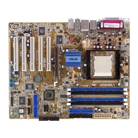
Hardware Installation Chapter 2 - Hardware Installation 2.1 System Board Layout DDR 1 +12V power DDR 2 Mouse CPU fan COM 1 ATX power COM 2 K8T800 IDE 1 IDE 2 1394_1 USB 1-2 USB 3-4 Line-in Line-out Mic-in CD-in PCI 1 Audio Codec... -
Page 16: System Memory
Hardware Installation Warning: Electrostatic discharge (ESD) can damage your system board, proces- sor, disk drives, add-in boards, and other components. Perform the upgrade instruction procedures described at an ESD workstation only. If such a station is not available, you can provide some ESD protection by wearing an antistatic wrist strap and attaching it to a metal part of the system chassis. -
Page 17: Installing The Dim Module
Hardware Installation BIOS Setting Configure the system memory in the Advanced Chipset Features submenu (“DRAM Configuration” section) of the BIOS. 2.2.1 Installing the DIM Module A DIM module simply snaps into a DIMM socket on the system board. Pin 1 of the DIM module must correspond with Pin 1 of the socket. -
Page 18: Cpu
Hardware Installation 2.3 CPU 2.3.1 Overview The system board is equipped with a surface mount 754-pin CPU socket. This socket is exclusively designed for installing an AMD CPU. 2.3.2 Installing the CPU 1. Make sure the PC and all other peripheral devices connected to it has been powered down. -
Page 19: Hardware Installation
Hardware Installation 4. Unlock the socket by pushing the lever sideways, away from the socket, then lifting it up to a 90 angle. Make sure the lever is lifted to at least this angle otherwise the CPU will not fit in properly. Lever 5. - Page 20 Hardware Installation 6. Insert the CPU into the socket until it is seated in place. The CPU will fit in only one orientation and can easily be inserted without exerting any force. Important: Do not force the CPU into the socket. Forcing the CPU into the socket may bend the pins and damage the CPU.
- Page 21 Hardware Installation 2.3.3 Installing the Fan and Heat Sink The CPU must be kept cool by using a CPU fan with heat sink. Without sufficient air circulation across the CPU and heat sink, the CPU will overheat damaging both the CPU and system board. Note: •...
- Page 22 Hardware Installation 3. Place the heat sink on top of the CPU. Now hook one side of the retention clip onto the retention module base by fitting the holes on the retention clip into the retaining tabs of the retention module base.
- Page 23 Hardware Installation 4. Hook the other side of the retention clip (the one near the retention lever) so that the holes on the retention clip also fit into the retaining tabs of the retention module base. Note: You will not be able to secure the fan and heat sink assembly in place if it did not fit properly onto the retention module base.
-
Page 24: Jumper Settings
Hardware Installation 2.4 Jumper Settings 2.4.1 Clear CMOS Data 1-2 On: Normal 2-3 On: (default) Clear CMOS Data If you encounter the following, a) CMOS data becomes corrupted. b) You forgot the keyboard, supervisor or user password. c) You are unable to boot-up the computer system because the processor’s clock was incorrectly set in the BIOS. - Page 25 Hardware Installation 4. After powering-on the system, press <Del> to enter the main menu of the BIOS. 5. Select the Frequency/Voltage Control submenu and press <En- ter>. 6. Set the “CPU Clock” field to its default setting or an appropriate bus clock.
- Page 26 Hardware Installation 2.4.2 5V/5VSB Power Select 1-2 On: 5V 2-3 On: 5VSB (default) JP1 is used to select between 5V and 5VSB power. Selecting 5VSB will allow you to use a PS/2 keyboard, PS/2 mouse or a USB device to wake up the system. BIOS Setting Configure the PS/2 and USB device wake up function in the Power Management Setup submenu (“IRQ/Event Activity Detect”...
-
Page 27: Rear Panel I/O Ports
Hardware Installation 2.5 Rear Panel I/O Ports PS/2 Parallel 1394_1 Mouse Line-in Line-out Mic-in PS/2 K/B COM 1 COM 2 USB 1-2 USB 3-4 The rear panel I/O ports consist of the following: • PS/2 mouse port • PS/2 keyboard port •... - Page 28 Hardware Installation 2.5.1 PS/2 Mouse and PS/2 Keyboard Ports PS/2 Mouse PS/2 Keyboard The system board is equipped with an onboard PS/2 mouse (Green) and PS/2 keyboard (Purple) ports - both at location CN1 of the system board. The PS/2 mouse port uses IRQ12. If a mouse is not connected to this port, the system will reserve IRQ12 for other expansion cards.
- Page 29 Hardware Installation • BIOS Setting: Configure the PS/2 wake up function in the Power Management Setup submenu (“IRQ/Event Activity Detect” section) of the BIOS. Refer to chapter 3 for more information. Important: The 5VSB power source of your power supply must support ≥...
-
Page 30: Serial Ports
Hardware Installation 2.5.2 Serial Ports COM 1 COM 2 The system board is equipped with two onboard serial ports (Teal/ Turquoise) at locations CN4 for COM 1 and CN10 for COM 2. The serial ports are RS-232C asynchronous communication ports with 16C550A-compatible UARTs that can be used with a modem, serial printer, remote display terminal or other serial devices. -
Page 31: Parallel Port
Hardware Installation 2.5.3 Parallel Port Parallel The system board has a standard parallel port (Burgundy) at loca- tion CN7 for interfacing your PC to a parallel printer. It supports SPP, ECP and EPP. Setting Function Allows normal speed operation but (Standard Parallel Port) in one direction only. - Page 32 Hardware Installation 2.5.4 IEEE 1394 (optional) 1394_1 1394_2 The system board is equipped with an onboard IEEE 1394 port at location CN6 (IEEE 1394_1) of the system board. It is also equipped with an IEEE 1394 connector at location J9 (1394_2) for connecting an additional 1394 device.
- Page 33 Hardware Installation 2.5.5 Universal Serial Bus Ports USB 2 USB 1 USB 4 USB 3 USB 5-6 USB 7-8 Four onboard USB 2.0/1.1 ports (Black) are at locations CN6 (USB 1-2) and CN5 (USB 3-4) of the system board. J7 (USB 5-6) and J8 (USB 7-8) connectors allow you to connect 4 additional USB 2.0/1.1 ports.
- Page 34 Hardware Installation Driver Installation You may need to install the proper drivers in your operating system to use the USB device. Refer to your operating system’s manual or documentation for more information. If you are using a USB 2.0 device, install the “VIA USB 2.0 Drivers”. Refer to chapter 4 for more information.
- Page 35 Hardware Installation 2.5.6 RJ45 Fast-Ethernet Port RJ45 LAN The system board is equipped with an onboard RJ45 fast-ethernet LAN port at location CN5 of the system board. It allows the system board to connect to a local area network by means of a network hub.
- Page 36 Hardware Installation 2.5.7 Audio (Rear Audio Jacks and Front Audio) Line-in Rear audio Line-out Mic-in 1 0 9 AuD_L_Return AuD_L_Out N. C. AuD_R_Return AuD_R_Out AuD_Vcc N. C. Front audio Line-in, Line-out and Mic-in The line-in, line-out and mic-in jacks are at location CN3 of the system board.
- Page 37 Hardware Installation Front Audio The front audio connector (J1) allows you to connect to the line-out and mic-in jacks that are at the front panel of your system. Using this connector will disable the rear audio’s line-out and mic-in func- tions.
-
Page 38: I/O Connectors
Hardware Installation 2.6 I/O Connectors 2.6.1 CD-in Internal Audio Connector Ground Ground Left audio Right audio channel channel The CD-in (J2) connector is used to receive audio from a CD-ROM drive, TV tuner or MPEG card. - Page 39 Hardware Installation 2.6.2 S/PDIF-in/out Connector SPDIF out SPDIF in The S/PDIF-in/out connector (J4) is used to connect external S/PDIF ports. Your S/PDIF ports may be mounted on a card-edge bracket. Install the card-edge bracket to the system chassis then connect the audio cable connector to J4.
-
Page 40: Floppy Disk Drive Connector
Hardware Installation 2.6.3 Floppy Disk Drive Connector The system board is equipped with a shrouded floppy disk drive connector for connecting two standard floppy disk drives. To prevent improper floppy cable installation, the shrouded floppy disk header has a keying mechanism. The 34-pin connector on the floppy cable can be placed into the header only if pin 1 of the connector is aligned with pin 1 of the header. -
Page 41: Serial Ata Connectors
Hardware Installation 2.6.4 Serial ATA Connectors SATA 2 SATA 1 The system board is equipped with two Serial ATA connectors for connecting Serial ATA devices. Connect one end of the Serial ATA cable to J15 (SATA 2) or J16 (SATA 1) and the other end to your serial ATA device. -
Page 42: Ide Disk Drive Connectors
Hardware Installation 2.6.5 IDE Disk Drive Connectors IDE 1 IDE 2 IDE 1 IDE 2 The system board is equipped with two shrouded PCI IDE headers that will interface four Enhanced IDE (Integrated Drive Electronics) disk drives. To prevent improper IDE cable installation, each shrouded PCI IDE header has a keying mechanism. - Page 43 Hardware Installation Note: Refer to your disk drive user’s manual for information about selecting proper drive switch settings. Adding a Second IDE Disk Drive When using two IDE drives, one must be set as the master and the other as the slave. Follow the instructions provided by the drive manufacturer for setting the jumpers and/or switches on the drives.
-
Page 44: Irda Connector
Hardware Installation 2.6.6 IrDA Connector IRRX N. C. Ground IRTX Connect your IrDA cable to connector J5 on the system board. Note: The sequence of the pin functions on some IrDA cable may be reversed from the pin function defined on the system board. Make sure to connect the cable to the IrDA connector according to their pin functions. -
Page 45: Cooling Fan Connectors
Hardware Installation 2.6.7 Cooling Fan Connectors Power Ground Sense CPU fan Power Ground N. C. Chassis fan Connect the CPU fan’s cable connector to the CPU fan connector (J20) on the system board. The chassis fan connector (J10) is used to connect an additional cooling fan. -
Page 46: Power Connectors
Hardware Installation 2.6.8 Power Connectors +12V +12V Ground Ground +12V 5VSB PW-OK Ground Ground Ground Ground Ground PS-ON Ground Ground -12V 3.3V 3.3V 3.3V Use a power supply that complies with the ATX12V Power Supply Design Guide Version 1.1. An ATX12V power supply has a standard 20-pin ATX main power connector and a 4-pin +12V power connector that must be inserted onto CN9 and CN8 connectors respectively. -
Page 47: Front Panel Connectors
Hardware Installation 2.6.9 Front Panel Connectors ATX-SW PWR-LED HD-LED SPEAKER RESET HD-LED: Primary/Secondary IDE LED This LED will light when the hard drive is being accessed. RESET: Reset Switch This switch allows you to reboot without having to power off the system thus prolonging the life of the power supply or system. - Page 48 Hardware Installation PWR-LED: Power/Standby LED When the system’s power is on, this LED will light. When the system is in the S1 (POS - Power On Suspend) or S3 (STR - Suspend To RAM) state, it will blink every second. Note: If a system did not boot-up and the Power/Standby LED did not light after it was powered-on, it may indicate that the CPU...
-
Page 49: Chapter 3 - Bios Setup
BIOS Setup Chapter 3 - BIOS Setup 3.1 Award BIOS Setup Utility The Basic Input/Output System (BIOS) is a program that takes care of the basic level of communication between the processor and peripherals. In addition, the BIOS also contains codes for various advanced features found in this system board. -
Page 50: Standard Cmos Features
BIOS Setup 3.1.1 Standard CMOS Features Use the arrow keys to highlight “Standard CMOS Features” and press <Enter>. A screen similar to the one below will appear. The settings on the screen are for reference only. Your version may not be identical to this one. - Page 51 BIOS Setup 3.1.1.3 IDE Primary Master, IDE Primary Slave, IDE Secondary Master and IDE Secondary Slave Move the cursor to the “IDE Primary Master”, “IDE Primary Slave”, “IDE Secondary Master” or “IDE Secondary Slave” field, then press <Enter>. The following screen will appear. The settings on the screen are for reference only.
- Page 52 BIOS Setup Capacity Displays the approximate capacity of the disk drive. Usually the size is slightly greater than the size of a formatted disk given by a disk checking program. Cylinder This field displays the number of cylinders. Head This field displays the number of read/write heads. Precomp This field displays the number of cylinders at which to change the write timing.
- Page 53 BIOS Setup 3.1.1.5 Video This field selects the type of video adapter used for the primary system monitor. Although secondary monitors are supported, you do not have to select the type. The default setting is EGA/VGA. EGA/VGA Enhanced Graphics Adapter/Video Graphics Array. For EGA, VGA, SVGA and PGA monitor adapters.
- Page 54 BIOS Setup 3.1.1.8 Extended Memory Displays the amount of extended memory detected during boot-up. 3.1.1.9 Total Memory Displays the total memory available in the system.
-
Page 55: Advanced Bios Features
BIOS Setup 3.1.2 Advanced BIOS Features The Advanced BIOS Features allows you to configure your system for basic operation. Some entries are defaults required by the system board, while others, if enabled, will improve the performance of your system or let you set some features according to your preference. The screen above list all the fields available in the Advanced BIOS Features submenu, for ease of reference in this manual. - Page 56 BIOS Setup operating systems like Windows ® 98/2000/ME/XP or the operating system may not install nor work. 3.1.2.2 CPU Internal Cache and External Cache These fields speed up the memory access. The default is Enabled, which provides better performance by enabling cache. 3.1.2.3 CPU L2 Cache ECC Checking The processors supported by the system board come with built-in Level 2 cache.
- Page 57 BIOS Setup 3.1.2.7 Boot Up Floppy Seek When enabled, the BIOS will check whether the floppy disk drive installed is 40 or 80 tracks. Note that the BIOS cannot distinguish between 720K, 1.2M, 1.44M and 2.88M drive types as they are all 80 tracks.
- Page 58 BIOS Setup 3.1.2.12 Security Option This field determines when the system will prompt for the password - everytime the system boots or only when you enter the BIOS setup. Set the password in the Set Supervisor/User Password submenu. System The system will not boot and access to Setup will be denied unless the correct password is entered at the prompt.
- Page 59 BIOS Setup 3.1.2.17 Video BIOS Shadow Determines whether video BIOS will be copied to RAM. Video Shadow will increase the video speed. Note that some graphics boards require that this option be disabled. The default value is Enabled. Enabled Video shadow is enabled. Disabled Video shadow is disabled.
-
Page 60: Advanced Chipset Features
BIOS Setup 3.1.3 Advanced Chipset Features The settings on the screen are for reference only. Your version may not be identical to this one. This section gives you functions to configure the system based on the specific features of the chipset. The chipset manages bus speeds and access to system memory resources. - Page 61 BIOS Setup 3.1.3.1 DRAM Configuration Move the cursor to this field and press <Enter>. The following screen will appear. The settings on the screen are for reference only. Your version may not be identical to this one. Current FSB Frequency This field will show the detected FSB of the CPU.
- Page 62 BIOS Setup 1T/2T Memory Timing 2T timing which provides better system stability is supported in CG or later revisions of the AMD Athlon 64 CPU. You can select 1T or 2T memory timing in this field. This field will not appear if you are using a CPU whose version is older than the CG revision.
- Page 63 BIOS Setup 3.1.3.2 AGP & P2P Bridge Control Move the cursor to this field and press <Enter>. The following screen will appear. The settings on the screen are for reference only. Your version may not be identical to this one. AGP Aperture Size This field is relevant to the memory-mapped graphics data of the AGP card installed in your system.
- Page 64 BIOS Setup AGP Fast Write Select Enabled to support the AGP Fast Write function. AGP Master 1 WS Write Set this field to Enabled to add one clock tick to AGP write operations. AGP Master 1 WS Read Set this field to Enabled to add one clock tick to AGP read opera- tions.
- Page 65 BIOS Setup 3.1.3.3 LDT & PCI Bus Control Move the cursor to this field and press <Enter>. The following screen will appear. The settings on the screen are for reference only. Your version may not be identical to this one. Upstream LDT Bus Width This field is used to select the upstream data width.
- Page 66 BIOS Setup PCI Delay Transaction When enabled, this function frees up the PCI bus for other PCI masters during the PCI-to-ISA transactions. This allows PCI and ISA buses to be used more efficiently and prevents degradation of performance on the PCI bus when ISA accesses are made. 3.1.3.4 Memory Hole This field is used to select the memory area that must not be addressed to the ISA bus.
-
Page 67: Integrated Peripherals
BIOS Setup 3.1.4 Integrated Peripherals The settings on the screen are for reference only. Your version may not be identical to this one. 3.1.4.1 VIA OnChip IDE Device Move the cursor to this field and press <Enter>. The following screen will appear. The settings on the screen are for reference only. - Page 68 BIOS Setup OnChip SATA This field is used to enable or disable the onboard SATA. IDE DMA Transfer Access This field, when Enabled, will enhance the IDE DMA transfer of an IDE hard disk drive. OnChip IDE Channel0 and OnChip IDE Channel1 These fields allow you to enable or disable the primary and second- ary IDE controller.
- Page 69 BIOS Setup Primary Master/Slave UDMA and Secondary Master/Slave UDMA These fields allow you to set the Ultra DMA in use. When Auto is selected, the BIOS will select the best available option after checking your hard drive or CD-ROM. Auto The BIOS will automatically detect the settings for you.
- Page 70 BIOS Setup 3.1.4.2 VIA OnChip PCI Device Move the cursor to this field and press <Enter>. The following screen will appear. The settings on the screen are for reference only. Your version may not be identi- cal to this one. VIA-3058 AC97 Audio Auto Select this option when using the onboard audio...
- Page 71 BIOS Setup OnChip USB Controller This field is used to select the USB ports you want enabled. OnChip EHCI Controller If you are using USB 2.0, this field must be set to Enabled. USB Emulation DOS does not support USB device. KB/MS DOS supports USB legacy keyboard and USB legacy mouse but does not suppor t any USB...
- Page 72 BIOS Setup 3.1.4.3 Super IO Device Move the cursor to this field and press <Enter>. The following screen will appear. The settings on the screen are for reference only. Your version may not be identical to this one. Onboard FDC Controller Enabled Enables the onboard floppy disk controller.
- Page 73 BIOS Setup UR2 Duplex Mode Half Data is completely transmitted before receiving data. Full Transmits and receives data simultaneously. Onboard Parallel Port 378/IRQ7, 3BC/IRQ7, 278/IRQ5 Selects the I/O address and IRQ for the onboard parallel port. Disabled Disables the onboard parallel port. Parallel Port Mode The options are SPP, EPP, ECP and ECP+EPP.
-
Page 74: Power Management Setup
BIOS Setup 3.1.5 Power Management Setup The Power Management Setup allows you to configure your system to most effectively save energy. The settings on the screen are for reference only. Your version may not be identical to this one. 3.1.5.1 ACPI Function This function should be enabled only in operating systems that ®... - Page 75 BIOS Setup 3.1.5.3 Power Management Option This field allows you to select the type (or degree) of power saving by changing the length of idle time that elapses before the “HDD Power Down” field is activated. Min Saving Minimum power saving time for the “HDD Power Down”...
- Page 76 BIOS Setup 3.1.5.8 MODEM Use IRQ This field is used to set an IRQ channel for the modem installed in your system. 3.1.5.9 Soft-Off by PWRBTN This field allows you to select the method of powering off your system. Delay 4 Sec. Regardless of whether the Power Management func- tion is enabled or disabled, if the power button is pushed and released in less than 4 sec, the system enters the Suspend mode.
- Page 77 BIOS Setup Important: Manually changing the CPU’s operating frequency and/or voltage are not guaranteed to provide better system performance. It may cause damage or result to the CPU’s or system’s instability. 3.1.5.14 IRQ/Event Activity Detect Move the cursor to this field and press <Enter>. The following screen will appear.
- Page 78 BIOS Setup PS2KB Wakeup from S3/S4/S5 The options in this field will allow you to use the PS/2 keyboard to wake up the system from the S3, S4 or S5 state. PS2MS Wakeup from S3/S4/S5 This field, when enabled, allows you to use a PS/2 mouse to wake up the system from the S3, S4 or S5 state.
- Page 79 BIOS Setup PowerOn by PCI Card Enabled This field should be set to Enabled only if your PCI card such as LAN card or modem card uses the PCI PME (Power Management Event) signal to remotely wake up the system. Access to the LAN card or PCI card will cause the system to wake up.
- Page 80 BIOS Setup IRQs Activity Monitoring Move the cursor to this field and press <Enter>. The “Primary INTR”, and “IRQ3” - “IRQ15” fields will appear. The settings on the screen are for reference only. Your version may not be identical to this one. When enabled, access to the specified IRQ will cause the system to wake up completely from the power management mode.
- Page 81 BIOS Setup 3.1.6 PnP/PCI Configurations This section describes configuring the PCI bus system. It covers some very technical items and it is strongly recommended that only experienced users should make any changes to the default settings. The settings on the screen are for reference only. Your version may not be identical to this one.
- Page 82 BIOS Setup 3.1.6.4 IRQ Resources Move the cursor to this field and press <Enter>. This field is used to set each system interrupt to either Reserved or PCI Device. The settings on the screen are for reference only. Your version may not be identical to this one.
- Page 83 BIOS Setup 3.1.6.7 Assign IRQ for USB When Enabled, the system automatically assigns an IRQ for the USB device connected to your system. However, if you are not using USB devices and an ISA slot requires an IRQ, set this field to Disabled. The IRQ previously occupied by the USB device will be available for the ISA slot.
-
Page 84: Pc Health Status
BIOS Setup 3.1.7 PC Health Status The settings on the screen are for reference only. Your version may not be identical to this one. 3.1.7.1 Shutdown Temperature You can prevent the system from overheating by selecting a tem- perature in this field. If the system detected that its temperature exceeded the one set in this field, it will automatically shutdown. - Page 85 BIOS Setup 3.1.7.6 System Temperature This field will show the current internal temperature of the system. 3.1.7.7 CPU Fan Speed This field will show the current fan speed of the CPU fan in RPM (Revolutions Per Minute).
- Page 86 BIOS Setup 3.1.8 Frequency/Voltage Control The settings on the screen are for reference only. Your version may not be identical to this one. 3.1.8.1 Auto Detect PCI Clk When enabled, the system will automatically send clock signals to existing PCI device. 3.1.8.2 Spread Spectrum Leave this field in its default setting.
- Page 87 BIOS Setup 3.1.8.4 CPU Voltage Control This field allows you to manually adjust to a higher core voltage that is supplied to the CPU. If you want to use the CPU’s default core voltage, leave this field in its default setting. The CPU’s Vcore will be generated according to the CPU VID configuration.
- Page 88 BIOS Setup 3.1.9 Load Fail-Safe Defaults The “Load Fail-Safe Defaults” option loads the troubleshooting default values permanently stored in the ROM chips. These settings are not optimal and turn off all high performance features. You should use these values only if you have hardware problems. Highlight this option in the main menu and press <Enter>.
-
Page 89: Load Optimized Defaults
BIOS Setup 3.1.10 Load Optimized Defaults The “Load Optimized Defaults” option loads optimized settings from the BIOS ROM. Use the default values as standard values for your system. Highlight this option in the main menu and press <Enter>. Type <Y> and press <Enter> to load the Setup default values. - Page 90 BIOS Setup 3.1.11 Set Supervisor Password If you want to protect your system and setup from unauthorized entry, set a supervisor’s password with the “System” option selected in the Advanced BIOS Features. If you want to protect access to setup only, but not your system, set a supervisor’s password with the “Setup”...
- Page 91 BIOS Setup 3.1.12 Set User Password If you want another user to have access only to your system but not to setup, set a user’s password with the “System” option se- lected in the Advanced BIOS Features. If you want a user to enter a password when trying to access setup, set a user’s password with the “Setup”...
- Page 92 BIOS Setup 3.1.13 Save & Exit Setup When all the changes have been made, highlight “Save & Exit Setup” and press <Enter>. Type “Y” and press <Enter>. The modifications you have made will be written into the CMOS memory, and the system will reboot. You will once again see the initial diagnostics on the screen.
-
Page 93: Exit Without Saving
BIOS Setup 3.1.14 Exit Without Saving When you do not want to save the changes you have made, highlight “Exit Without Saving” and press <Enter>. Type “Y” and press <Enter>. The system will reboot and you will once again see the initial diagnostics on the screen. If you wish to make any changes to the setup, press <Ctrl>... -
Page 94: Updating The Bios
BIOS Setup 3.3 Updating the BIOS To update the BIOS, you will need the new BIOS file and a flash utility, AWDFLASH.EXE. You can download them from DFI’s web site or contact technical support or your sales representative. 1. Save the new BIOS file along with the flash utility AWDFLASH.EXE to a floppy disk. - Page 95 BIOS Setup 6. The following will appear. Do You Want to Save BIOS (Y/N) This question refers to the current existing BIOS in your system. We recommend that you save the current BIOS and its flash utility; just in case you need to reinstall the BIOS. To save the current BIOS, press <Y>...
-
Page 96: Chapter 4 - Supported Softwares
Supported Software Chapter 4 - Supported Software 4.1 Desktop Management Interface (DMI) The mainboard comes with a DMI built into the BIOS. DMI, along with the appropriately networked software, is designed to make inventory, maintenance and troubleshooting of computer systems easier. With DMI, a network administrator or MIS engineer can remotely access some information about a particular computer system without physically going to it. -
Page 97: Using The Dmi Utility
Supported Software 4.1.2 Using the DMI Utility Award DMI Configuration Utility Copyright Award Software Inc, 1996 [Edit DMI] [Add DMI] [Load DMI File] [Save DMI File] BIOS *** BIOS Auto Detect *** System Enclosure/Chassis Type : BIOS Information... -
Page 98: Add Dmi
Supported Software Add DMI 1. Use the ← or → arrow keys to select the Add DMI menu. 2. Highlight the item on the left screen that you would like to add by using the ↑ or ↓ arrow keys, then press <Enter>. 3. -
Page 99: Drivers, Utilities And Software Applications
Supported Software 4.2 Drivers, Utilities and Software Applications The CD that came with the system board contains drivers, utilities and software applications required to enhance the performance of the system board. Inser t the CD into a CD-ROM drive. The autorun screen (Mainboard Utility CD) will appear. - Page 100 Supported Software ® 4.2.1 VIA Service Pack ® The VIA Service Pack contains the following drivers. • VIA ATAPI Vendor Support Driver • AGP VxD Driver • IRQ Routing Miniport Driver • VIA INF Driver To install VIA Service Pack, please follow the steps below. 1.
- Page 101 Supported Software ® Service Pack Installation Notes The “AGP VxD Driver” and “VIA INF Driver” drivers in the “VIA ® ® Service Pack” are supported in Windows 95, Windows ® ® ® Windows 98 SE, Windows ME and Windows 2000. ®...
-
Page 102: Audio Drivers
Supported Software 4.2.2 Audio Drivers The audio drivers are supported in the following operating systems: Windows 98, Windows 98 SE, Windows ME, Windows NT 4.0, Windows 2000 and Windows To install the driver, please follow the steps below. 1. - Page 103 Supported Software 3. The following screen will appear. 4. Follow the prompts on the screen to complete installation. 5. Reboot the system for the driver to take effect. Note: The 3D Audio Configuration software, which is an audio panel for setting basic audio configurations, will at the same time be installed into your system.
- Page 104 Supported Software 4.2.3 VIA USB 2.0 Drivers To install the USB 2.0 driver, please follow the steps below. 1. On the left side of the autorun screen, click the “USB” icon. 2. Click “VIA USB 2.0 Drivers”. The following screen will appear. 3.
- Page 105 Supported Software 4.2.4 VIA LAN Drivers The LAN drivers for Windows 98, Windows 98 SE, Windows ME, Windows 2000 and Windows XP support “Autorun”. To install the LAN driver, please follow the steps below. 1. On the left side of the autorun screen, click the “NETWORK” icon.
- Page 106 Supported Software 4.2.5 VIA SATA RAID Drivers and Utility If you are configuring RAID on the SATA drives, you must install the SATA RAID Drivers. 1. On the left side of the autorun screen, click the “TOOLS” icon. 2. Click “VIA SATA RAID Drivers and Utility” on the main screen. The following screen will appear.
- Page 107 Supported Software If your system board package does not include the diskette, prepare a blank formatted diskette then copy all the SATA driver files from the SATA\DRIVERDISK directory of the provided CD into the blank diskette. You can now use the diskette to install the drivers. Note: Refer to the VIA SATA RAID manual for information on using the utility.
- Page 108 Supported Software 4.2.7 Microsoft DirectX 9 To install, please follow the steps below. 1. On the left side of the autorun screen, click the “TOOLS” icon. 2. Click “Microsoft DirectX 9” on the main menu. The following screen will appear. 3.
-
Page 109: Audio Configuration
Supported Software 4.3 3D Audio Configuration When you install the audio driver, the 3D Audio Configuration software will at the same time be installed into your system. 3D Audio Configuration is an audio panel for setting basic audio configurations. It allows you to configure 2-channel, 4-channel and 6- channel audio modes as well as configure the audio effects. -
Page 110: Installation Notes
Supported Software Xear 3D Xear 3D is a sound technology for 2-channel virtual surround, adjustable multi-channel sound field, innovative listening mode, amazing sound effects and 3D positional audio. It has 3 functional blocks: Virtual Speaker Shifter, Sound Effect and Multi-channel Music Demo. -
Page 111: Using The Suspend To Ram Function
Using the Suspend to RAM Function Appendix A - Using the Suspend to RAM Function A.1 Using the Suspend to RAM Function ® ® ® ® ® If you are using the Windows 98 operating system, please follow the steps below. Select “Power Management Setup”... - Page 112 Using the Suspend to RAM Function ® ® ® ® ® ® ® ® ® ® Boot Windows 98. In the Windows 98 desktop, click the Start button. Move the cursor to Settings, then click Control Panel. To check whether ACPI was properly installed, double-click the System icon.
- Page 113 Using the Suspend to RAM Function Click File System. In the “Typical role of this computer” field, select “Mobile or docking system”. Click Apply, then click OK. Restart the computer. 10. Repeat step 7 to open the Control Panel dialog box. Double- click the Power Management icon.
- Page 114 Using the Suspend to RAM Function 12. After completing the steps above and you want to power-off the computer, you do not need to go through the process of closing files, applications and operating system. You can power- off the computer at once by pressing the power button or ®...
-
Page 115: Appendix B - System Error Messages
System Error Message Appendix B - System Error Message When the BIOS encounters an error that requires the user to cor- rect something, either a beep code will sound or a message will be displayed in a box in the middle of the screen and the message, PRESS F1 TO CONTINUE, CTRL-ALT-ESC or DEL TO ENTER SETUP, will be shown in the information box at the bottom. - Page 116 System Error Message Hard Disk(s) fail (80) HDD reset failed. Hard Disk(s) fail (40) HDD controller diagnostics failed. Hard Disk(s) fail (20) HDD initialization error. Hard Disk(s) fail (10) Unable to recalibrate fixed disk. Hard Disk(s) fail (08) Sector Verify failed. Keyboard is locked out - Unlock the key The BIOS detects that the keyboard is locked.
-
Page 117: Appendix C - Troubleshooting
Troubleshooting Appendix C - Troubleshooting C.1 Troubleshooting Checklist This chapter of the manual is designed to help you with problems that you may encounter with your personal computer. To efficiently troubleshoot your system, treat each problem individually. This is to ensure an accurate diagnosis of the problem in case a problem has multiple causes. -
Page 118: Floppy Drive
Troubleshooting The picture seems to be constantly moving. 1. The monitor has lost its vertical sync. Adjust the monitor’s verti- cal sync. 2. Move away any objects, such as another monitor or fan, that may be creating a magnetic field around the display. 3. -
Page 119: Hard Drive
Troubleshooting Hard Drive Hard disk failure. 1. Make sure the correct drive type for the hard disk drive has been entered in the BIOS. 2. If the system is configured with two hard drives, make sure the bootable (first) hard drive is configured as Master and the sec- ond hard drive is configured as Slave. - Page 120 Troubleshooting 3. Verify that the attached serial device works by attaching it to a serial port that is working and configured correctly. If the serial device does not work, either the cable or the serial device has a problem. If the serial device works, the problem may be due to the onboard I/O or the address setting.