Electrolux W475H Installation Manual
Hide thumbs
Also See for W475H:
- Operating manual (76 pages) ,
- Installation manual (60 pages) ,
- User manual (20 pages)

Related Manuals for Electrolux W475H


Summary of Contents for Electrolux W475H
- Page 1 Installation manual W475H/N/S, W485N/S, W4105H/N/S, W4130H/N/S, W4180H/N/S, W4240H/N/S, W4250N/S, W4300H, W4330N/S Compass Control 438 9037-38/US 09.38...
- Page 3 Safety and warning signs SAFETY AND WARNINGS SIGNS Replace If Missing Or Illegible One or more of these signs must be affixed on each machine as indica- ted, when not included as part of the front instruction panel. LOCATED ON THE OPERATING INSTRUCTION SIGN OF THE MACHINE: CAUTION 1.
- Page 4 Safety and warning signs IMPORTANT SAFETY INSTRUCTIONS WARNING - To reduce the risk of fire, electric chock, or injury to persons when using your appliance: 1. Read all instructions before using the appliance. 2. This machine must be securely bolted to the floor according to the installation instructions. 3.
- Page 5 Safety and warning signs NOTICE TO: OWNERS, OPERATORS AND DEALERS IMPROPER INSTALLATION AND INADEQUATE MAINTENANCE, POOR HOUSEKEEPING AND WILL FUL NEGLECT OR BYPASSING OF SAFETY DEVICES MAY RESULT IN SERIOUS ACCI- DENTS OR INJURY. TO ASSURE THE SAFETY OF CUSTOMERS AND/OR OPE RATORS OF YOUR MACHINE, THE FOLLOWING MAINTENANCE CHECKS MUST BE PERFORMED ON A DAILY BASIS.
- Page 6 Improper fastening of this machine to its foundation, inferior foundation materials, an undersized foundation, the use of fabricated steel bases not provided by Electrolux or its approved supplier(s), the use of an improper type, number, or size of mounting bolts, or failure to use proper hardware on mounting bolts may result in damage to the machine that will not be covered by the manufacturer's warranty.
-
Page 7: Table Of Contents
Contents Contents Safety precautions ..................9 Technical data ..................11 Installation W475H-W4330H ..............19 Transportation and unpacking, W475H, W4105H ......19 Transportation and unpacking, W4130H-W4300H ......20 Siting and floor ..................21 Mechanical installation ................22 Installation W485N/S-W4330N/S .............23 Siting ....................23 Floor ....................23 Casting a plinth ...................24 Installing the machine .................26... -
Page 9: Safety Precautions
Safety Precautions Safety Precautions The machine is designed for water washing only. The machine must not be used by children. All installation operations are to be carried out by qualified personnel. Licensed per- sonnel are necessary for all electric power wiring and plumbing Do not hose down the machine with water. -
Page 11: Technical Data
Technical data Technical data W475H W4105H W4130H W4180H W4240H W4300H Innerdrum volume litres/ft 75/2.6 105/3.7 130/4.6 180/6.4 240/8.5 300/10.6 diameter mm/inch 520/20 1/2 595/23 7/16 650/25 9/16 725/28 9/16 795/31 5/16 795/31 5/16 Drum speed wash extraction 1100 1025 Heating electricity 5.4/7.5... - Page 12 Technical data Technical data W485N/S W4105N/S W4130N/S W4180N/S W4250N/S W4330N/S Innerdrum volume litres/ft 85/3.0 105/3.7 130/4.6 180/6.4 250/8.8 330/11.7 diameter mm/inch 520/20 1/2 595/23 7/16 595/23 7/16 650/25 9/16 725/28 9/16 795/31 5/16 Drum speed wash extraction 587/830 548/776 548/776 525/742 497/702 474/671...
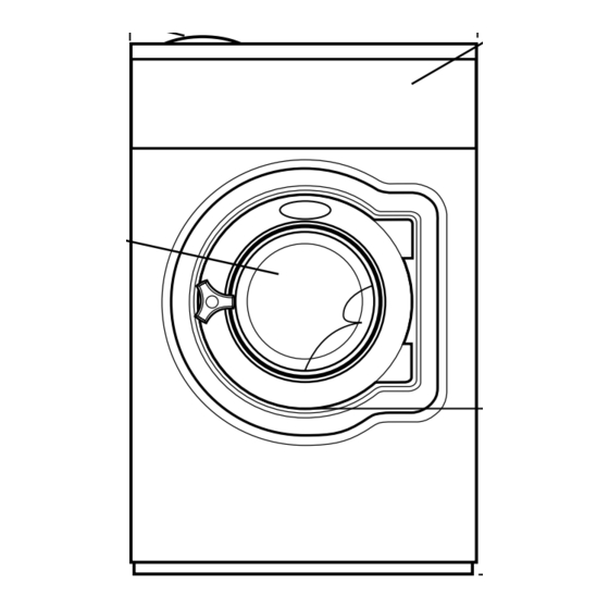
- Page 13 Drain Liquid detergent supply Control panel Soap box Door opening, W475H: ø 310 mm/12 3/16", W4105H: ø 365 mm/14 3/8", W4130H: ø 395 mm/15 9/16", W4180H, W4240H, W4300H: ø 435 mm/17 1/8" W475H 720 690 1115 355 1030 220 1010 135 100 240 –...
- Page 14 11 13/16 48 13/16 13 3/4 14 15/16 3 5/16 14 3/16 20 1/16 W4300H 12 3/16 14 15/16 – – 3 15/16 14 3/16 13 3/16 W475H, W4105H, W4130H 5282 B 5281 B 5283 B Front Right side Rear side W4180H, W4240H, W4300H...
- Page 15 Technical data Electrical connection Cold water Hot water Steam connection Drain Liquid detergent supply Control panel Soap box Water reuse Door opening, W485S: ø 310 mm/12 3/16", W4105S, W4130S: ø 365 mm/14 3/8", W4180S: ø 395 mm/15 9/16", W4250S, W4330S: ø 435 mm/17 1/8" W485N/S 730 1115 355 45 1030 215 1010 130...
- Page 16 Technical data in inch W485N/S 28 3/4 43 7/8 30 1/8 32 1/2 1 3/4 40 9/16 8 7/16 39 3/4 W4105N/S 28 3/8 27 3/4 47 1/4 14 3/8 29 1/8 35 13/16 1 3/4 40 7/8 8 7/16 43 1/8 W4130N/S 28 3/8...
- Page 17 Technical data W475H W4105H W4130H W4180H W4240H W4300H Frequency of the dynamic force 18.3 17.1 16.3 15.5 14.8 13.7 Max floor load lbs force 417±110 560±112 703±114 944±221 1158±221 1387±277 at extraction 1.9±0.5 2.5±0.5 3.1±0.5 4.2±1.0 5.2±1.0 6.2±1.2 W485N/S W4105N/S...
-
Page 19: Installation W475H-W4330H
Installation Installation W475H-W4330H Transportation and unpacking, W475H, W4105H The machine is delivered complete with expan- sion bolts etc. packed inside the machine in the drum. The machine is delivered bolted onto the trans- port pallet and packed in a crate or box. -
Page 20: Transportation And Unpacking, W4130H-W4300H
Installation Transportation and unpacking, W4130H, W4180H, W4240H, W4300H The machine is delivered complete with expan- sion bolts etc. packed inside the machine in the drum. The machine is delivered bolted onto the trans- port pallet and packed in a crate or box. • Remove packing from the machine. -
Page 21: Siting And Floor
Installation Siting and floor Install the machine close to a floor drain or open drain. In order to make installation and servicing the ma chine easier the following clearances are recommended: • At least 20 inches (500 mm) between the machine and the wall behind 500 mm 50 mm • and min. 2 inches (50 mm) on both sides of 20"... -
Page 22: Mechanical Installation
Installation Mechanical installation • Mark and drill 2 holes (ø 8 mm/5/16") about 40 mm/1 9/16" deep (W475H-W4105H) and ø 10 mm/3/8" and 50 mm/2" deep (W4130H- W4300H) in the positions. = position of feet = drilling points for expander bolts • The machine must be lifted in its base frame. • Place the machine over the two drilled holes on the foundation. -
Page 23: Installation W485N/S-W4330N/S
Installation Installation W485N/S-W4330N/S Leave the machine on the tran s port pallet until it can be placed in the final, pre pared position. Siting Install the machine close to a floor drain or open drain. In order to make installation and servicing the machine easier the following clearances are recommended: • At least 20 inches (500 mm) between the... -
Page 24: Casting A Plinth
Installation Casting a plinth A foundation should be used where the existing floor is less than 8 inches (200 mm) thick or in order to ensure that the machine is securely anchored and will not vibrate excessively. The foundation must be at least 8 inches (200 mm) thick. - Page 25 Installation Model W4330S For this machine two expander bolts shall be mounted at the front part of the machine. • Drill two holes (1) ø10 mm/ 3/8" and 40 mm/ 1 9/16" deep. • After the machine has been placed over the other four bolts, place the two spacer wash- ers over the two holes. They shall be placed between the machine and foundation.
-
Page 26: Installing The Machine
Installation Installing the machine To install the machine: • Remove the transport packaging • Remove the front panel. • Remove the machine from the transport pallet and locate it on the bolts. Always lift the ma ch ine by the chassis, never by the door or door handle. • Check that the machine is level and steady at all four corner mounting points. Adjust the level by using stain less or galvanized steel washers or shims be tween the machine and the floor. -
Page 27: Water Connections
Installation Water connections All inlet connections to the machine are to be fitted with manual shut-off valves and filters, to facilitate installation and servicing. Water pipes and hoses should be flushed clean before installation. After installation, hoses should hang in gentle arcs. Hoses are to be of an approved type and grade, to comply with national regulations. - Page 28 Installation Water type Water connection cold and cold hot W475H, W4105H, cold and W4130H cold hot cold*/ W485N/S, W4105N/S W4130N/S 5328 * For detergent container. Extra water valve which can be used for hard water if soft water is connected to 1.
-
Page 29: Drain Connection
Installation Drain connection Connect a 3 inch O.D. (75 mm) pipe or rubber hose to the machine’s drain pipe, ensuring a downward flow from the machine. Avoid sharp bends which may prevent proper draining. The washer may drain in to a drainage through or into a closed drain system. -
Page 30: Steam Connection
Installation Steam connection Inlet pipes connected to the machine must be equipped with a manual shut-off valve to facili- tate installation and servicing. The connection hose must be of type ISO/1307- 1983 or equivalent. Connection size at filter: DN 15 (BSP 1/2"). Steam pressure required: 6600 • minimum: 7 psi (50 kPa) -
Page 31: Connection Of External Liquid Supplies
Installation Connection of external liquid supplies 1 = N 2 = L 4 = Ground The external dosing equipment power supply must never be connected to the machine’s incoming terminal block. Machines fitted with connectors 1 = N • Connect the pump equipment to connections 2 = Program run A and B on the washing machine. - Page 32 Installation Outputs • Connect external power supply (e.g. 24V DC) Dosing system for pumps to 9 and 10. If an internal power supply (from the washing machine) is being used, it can be taken from 1 (N) and connec- ted to 9 and from 2 (L) and connected to 10. Max load on the outputs 0.5 A.
- Page 33 Installation • Connection 8 may be connected if the washing program is to pause, e.g. while washing detergent is being dosed. The figure shows an example of engaging a 24V pause signal. The washing program will pause for as long as the pause signal remains activated (high). Dosing system Pause signal 24V DC 6266 Detergent tank Empty 230V...
-
Page 34: Functions For I/O-Cards
Installation Functions for I/O -cards • Check the electrical schematic for the machine to find out what functions are available for the machine. Type of I/O card Address Function I/O:s Inp opt P out V in Out 5NO Out CO 6315 • Heating pause: Signal can be connected to connection 6 to pause the machine whilst it heats up. -
Page 35: Electrical Installation
Installation Electrical installation Electrical installation must be carried out by licensed, qualified personnel! Machines with frequency-controlled motors can be incompatible with certain types of earth leakage circuit breakers. It is important to know that the machines are designed to provide a high level of personal safety, which is why items such as ground-fault interrup- ting circuit breakers are not necessary. - Page 36 Installation Single-phase connection: Connect the earth and other two wires as shown in example ”1AC” in the figure. Three-phase connection: Connect the earth and the three phases as shown in example ”3AC” in the figure. When the installation is completed, check: • that the drum is empty.
- Page 37 Installation W475H Heating Voltage Total Fuse alternative alternative No heating 100-120 V 1 AC or Steam 208-240 V 1 AC heating El heating 220-230 V 3 AC W4105H Heating Voltage Total Fuse alternative alternative No heating 208-240 V 1 AC...
- Page 38 Installation W4180H Heating Voltage Total Fuse alternative alternative No heating 208-240 V 1 AC or Steam heating El heating 208-240 V 3 AC 17.5 W4240H Heating Voltage Total Fuse alternative alternative No heating 208-240 V 1 AC or Steam heating El heating 208-240 V 3 AC 18.3...
- Page 39 Installation W485N/S Heating Voltage Total Fuse alternative alternative No heating 120 V 1 AC or Steam 208-240 V 1 AC heating El heating 208-240 V 3 AC W4105N/S Heating Voltage Total Fuse alternative alternative No heating 120 V 1 AC 0.75 or Steam 208-240 V 1 AC...
- Page 40 Installation W4180N/S Heating Voltage Total Fuse alternative alternative No heating 120 V 1 AC or Steam 208-240 V 1 AC heating El heating 208-240 V 1 AC 12.1 208-240 V 3 AC 12.7 W4250N/S Heating Voltage Total Fuse alternative alternative No heating 120 V 1 AC or Steam...
-
Page 41: Function Checks
Function checks Function checks Perform the following checks once the machine is installed: • Open the manual water valves. • Turn on the power to the machine. • Put detergent into compartment 2 (Main wash). • Select a "HOT" program with the control knob (1). • Press the knob. Check: • that the drum rotates normally and that there 6217, 6179, 6204 are no unusual noises. • that there are no leaks in water supply/drain connections. • that water passes through the detergent compartment and fabric conditioner compart- ment. - Page 44 Share more of our thinking at www.electrolux.com...