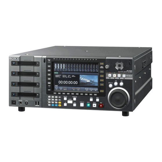
Sony SR-R1000 Operation Manual
Memory storage unit
Hide thumbs
Also See for SR-R1000:
- Brochure (17 pages) ,
- Operation manual (70 pages) ,
- Installation manual (42 pages)
Table of Contents
Advertisement
Quick Links
Download this manual
See also:
Installation Manual
Advertisement
Table of Contents

Related Manuals for Sony SR-R1000


Summary of Contents for Sony SR-R1000
- Page 1 MEMORY STORAGE UNIT SR-R1000 OPERATION MANUAL [English] 1st Edition (Revised 1)
-
Page 2: Important Safety Instructions
THIS APPARATUS MUST BE EARTHED. Before operating the unit, please read this manual thoroughly and retain it for future reference. CAUTION Danger of explosion if battery is incorrectly replaced. Important Safety Instructions Replace only with the same or equivalent type recommended by the manufacturer. - Page 3 In order to use this product safely, avoid prolonged For the customers in Europe listening at excessive sound pressure levels. The manufacturer of this product is Sony Corporation, 1- 7-1 Konan, Minato-ku, Tokyo, Japan. WARNING The Authorized Representative for EMC and product...
- Page 4 à l’interrupteur principal. contrôlé, ex. studio de télévision). Pour mettre l’appareil complètement hors tension, éteignez l’interrupteur électrique principal sur le panneau Pour les clients en Europe arrière. Le fabricant de ce produit est Sony Corporation, 1-7-1 Konan, Minato-ku, Tokyo, Japon.
- Page 5 VORSICHT Le représentant autorisé pour EMC et la sécurité des produits est Sony Deutschland GmbH, Hedelfinger Strasse Explosionsgefahr bei Verwendung falscher Batterien. 61, 70327 Stuttgart, Allemagne. Pour toute question Batterien nur durch den vom Hersteller empfohlenen oder concernant le service ou la garantie, veuillez consulter les einen gleichwertigen Typ ersetzen.
- Page 6 (Störfestigkeit) Für die folgende elektromagnetische Umgebung: E4 (kontrollierter EMV-Bereich, z.B. Fernsehstudio). Für Kunden in Europa Der Hersteller dieses Produkts ist Sony Corporation, 1-7-1 Konan, Minato-ku, Tokyo, Japan. Der autorisierte Repräsentant für EMV und Produktsicherheit ist Sony Deutschland GmbH, Hedelfinger Strasse 61, 70327 Stuttgart, Deutschland. Bei...
-
Page 7: Table Of Contents
Table of Contents Chapter 1 Overview Features..................10 High-Quality Recording ..............10 Multiple Ports ..................10 Multiple Resolutions................10 Large Storage Capacity................ 10 Other Features..................11 Chapter 2 Names and Functions of Parts Control Panel ................. 12 Connector Panel ................17 Display Screen................ - Page 8 Virtual Volumes................35 Synchronizing the Input and Output Ports ......... 38 Chapter 4 Basic Operations Selecting Input/Output Ports and SRMemory Slots ....41 Recording ..................42 Playback ..................43 Chasing Playback ................43 Variable Speed Playback..............43 Continuous Playback ................45 Still Picture Output ................
- Page 9 Troubleshooting ................71 Salvaging SRMemory Card in the Event Recording does not End Normally..................71 Error Messages ..................73 Warning Messages................75 ERROR LOG Menu ................79 Switching the Signal Format (HD/SD) of the Output Ports ....79 Recording Formats................80 Playback Format Conversions (1) ............
-
Page 10: Chapter 1 Overview
This allows you to record and play back a pair of 3D The SR-R1000 is a storage unit that supports recording and stereoscopic signals or fill/key signals with just a single port. -
Page 11: Other Features
• FTP protocol is supported for video data transfer in MXF format via a network. • Equipped with two network ports that support Gigabit Ethernet. • Compatible with Sony VTR protocol, Sony Disk protocol, etc. and switcher and controller operations are supported. Features... -
Page 12: Chapter 2 Names And Functions Of Parts
Names and Functions of Parts Chapter Control Panel The control panel consists of the following sections: A SRMemory slot section B Menu control section C Port control section (see page 13) (see page 14) (see page 15) G Search control section (see page 16) F Recording/playback control section (see page 15) E Editing control section (see page 15) D Numeric buttons (see page 15) -
Page 13: Srmemory Slot
A SRMemory slot section card or perform the appropriate operation as instructed by the message that appears on the control panel. 1) Flashing LED: Flashes at 1-second interval. Fast flashing LED: Flashes at 1/4-second interval. For details on salvage operations and formatting when problems have occurred, see “Troubleshooting”... - Page 14 B Menu control section a DISPLAY button h DIAG (diagnostic) button Used to switch between a screen displaying input/output Displays the maintenance menu when pressed together port information and a screen displaying the video signal with the SFT button. on the entire display. i MEM button b CH (channel) selection buttons Currently cannot be used.
- Page 15 C Port control section E Editing control section Currently cannot be used. F Recording/playback control section a Cursor buttons Move the cursor (shown in reverse video) on the display. Also used to change settings values. b PORT SELECT buttons/indicators (page 41) Buttons: Select the input/output port to use.
-
Page 16: Shuttle Button
G Search control section a SHUTTLE button Press to enter shuttle mode. In this mode, the button is lit and playback at the speed corresponding to the position of the search dial is possible (–100 to +100 times normal playback speed). The search dial clicks at the positions for still pictures and ±10 times normal playback speed. -
Page 17: Connector Panel
Connector Panel A Input/output ports (see page 17) Port A Port B Port C Port D B Remote input/output C Analog output/power supply * At the time of shipment from the factory, no boards are connected to ports A to C. section (see page 18) section (see page 19) An output board is connected to port D. - Page 18 9-pin connector. burst signal. A loop-through connection is also possible. Set the 75 Ω The Sony 9-pin VTR protocol, Sony 9-pin Disk protocol, VDCP protocol and Odetics protocol are supported. terminal switch to OFF if you are using a loop-through...
- Page 19 d GPIO (25-pin) connector b Main power switch A parallel I/O connector. Turns on/off the main power supply. When the main power See the Maintenance Manual and Interface Manual for is turned on, the On/Standby indicator on the control panel details.
-
Page 20: Display Screen
Display Screen The color display of the unit is capable of displaying a four-port display screen that shows all of the four ports and a one-port display screen that shows only the selected port. When the screen is four-port display, pressing the PORT SELECT button of the selected port switches to one-port display. - Page 21 One-port display b Audio level meters APort information display section (see page 21) BStatus bar (see page 22) a Menu display section a Menu display section (page 51) b Audio level meters Displays a menu. Displays the audio recording/playback levels. The meters are only displayed in the one-port display screen.
-
Page 22: Status Bar
One-port display n Time code (Second area) a Port name l F1/F2 Indicates the field number. b SRMemory slot name m Time code c File name Indicates the time code based on the setting of the TC menu. d Video format n Time code (Second area) Displays the video format according to port type. -
Page 23: Video Display
f Network access All slot numbers are displayed when recording and editing on all SRMemory cards are inhibited with the ALT/[F9] When an SRMemory card that is inserted in the unit is (REC INHI) buttons in the HOME menu. being accessed via the network, this indicates the storage that is being accessed by the connected session. -
Page 24: Time Code
One-port video display f Format information on video being recorded/played e Name of file being recorded/played d Time code c Recording/playback mark b SRMemory slot name a Port name Information on each port is displayed under the video for both the four-port and one-port display. a Port name b SRMemory slot name c Recording/playback mark... -
Page 25: File List Screen
File List Screen Press the memory selection buttons to display the list of files in the SRMemory card inserted. a SRMemory slot name b Remaining capacity c Number of files d Flag indication e File list f Detailed file information a SRMemory slot name •... -
Page 26: Chapter 3 Setting Up The Memory Storage Unit
Setting Up the Memory Storage Unit Chapter Connecting External HD digital recorder Devices This section describes how to connect the unit to external devices to record or play back data. In the explanations in this section, input boards are connected to ports A and C, and output boards to ports B and D. -
Page 27: Reference Signals
Reference Signals This section describes how the reference signals for video output are selected. Reference Signals for Output Video Signals The output video signals of the unit are synchronized and output as follows depending on the unit’s operation state, settings, and input signals. Start Input What is the setting of the... -
Page 28: Reference Signal Connections
For playback Reference Signal Connections Reference signal Connect reference signals as follows, according to your recording or playback requirements. Reference signal connections For recording signals from a switcher or signal generator Reference signal 75 Ω terminal switch: ON Switcher or signal generator HD serial input monitor Note... -
Page 29: Time Code Settings
Setting the Time Code Generator Time Code Settings The output of the unit’s internal time code generator is used to record time codes. The output from the internal time code generator can either Selecting the Time Data be set to any initial value, or synchronized with an external time code generator. -
Page 30: Time Code Conversion
For TC (time codes) or UB (user bits) The internal time code generator is reset and the time data display becomes 00:00:00:00 (for TC) or 00 00 00 00 (for UB). Notes • The values read by the time code reader cannot be reset. •... - Page 31 To make time code conversion settings In such a case, the file’s time code can be output while being converted in accordance with the running frame With the output port selected, press ALT/[F2] (TC CONV) frequency. in the TC menu. The one-port display appears and the time data display area changes to the time code conversion screen.
-
Page 32: Superimposing Character Information
To set the time code being played to Superimposing Character Starting TC Press the [F2] (ENTRY) key. The value of the time code Information being played at that time (recorded time code) is set as the Starting TC. To superimpose characters representing the time data, To set the Jumping TC value operation mode, and other information on output signals, set the ALT/[F10] (CHAR ON) buttons to On in the TC... - Page 33 b Drop frame mark of the time code reader blinking warning/error count will be shown in the second “.”: Drop frame mode line. “:”: Non-drop frame mode For details on error messages, see “Error Messages” c Drop frame mark of the time code generator (page 73).
-
Page 34: Handling Srmemory Cards
In the three character area to the right of the channel Handling SRMemory numbers, the audio levels are displayed in bar graph format extending from left to right. Cards Although the display is linked to the control panel’s audio meter, it is not suitable for level adjustment, etc. Use the state of audio output as a guide. -
Page 35: Preventing Accidental Data Loss
Inserting SRMemory cards Virtual Volumes Three SRMemory cards of the same type can be used as a single virtual volume with triple the capacity for storage. This is useful when you want to record continuously for prolonged periods. The maximum continuous recording time is 24 hours. - Page 36 When formatting completes properly, the card will be Notes ready for use as a standard SRMemory card. • Make sure all three cards are of the same type. • To enable formatting, release the write-protect Note switch and the file/card locks on each card If you format any one of the three cards that compose a beforehand.
- Page 37 Code Display Description Code Display Description ERROR- PORT x MAX This error message WARNING- VIRTUAL This warning message E10App LENGTH, STOP appears when recording is E40100 to VOLUME appears when the stopped automatically to WARNING- WRONG SRMemory cards that prevent the maximum E40500 POSITION compose the virtual...
-
Page 38: Synchronizing The Input And Output Ports
Press the [F9] (SRmemory INFO DISP) button. Synchronizing the Input The display changes to the SRMemory information screen. SRMemory information for slots M2, M3, and M4 appears and Output Ports from left to right. Press the [F9] button. You can synchronize an input port with other input ports or an output port with other output ports. - Page 39 ALT/[F1] (SYNC) selection in the HOME ALT/[F1] (SYNC) selection in the HOME menu menu Port P&File Port P&File Examples for • When you want to • When you want to PREV button • Playback position Synchronized. play back multiple synchronize more operations in middle of file: •...
- Page 40 ALT/[F1] (SYNC) selection in the HOME menu Port P&File Four-port The selected port The selected port display on appears in an orange appears in an orange LCD screen frame. frame. The port The port synchronized to the synchronized to the selected port selected port appears in a dark...
-
Page 41: Chapter 4 Basic Operations
Basic Operations Chapter Perform a recording or playback operation. Selecting Input/Output When recording to an SRMemory card from an input port Ports and SRMemory and when playing back data from an SRMemory card to an output port, select the port first and then the SRMemory Slots slot. -
Page 42: Recording
Recording simultaneously to one Recording SRMemory card The input signal from another port can be simultaneously recorded to the SRMemory card during recording. To This section describes the example of recording input record simultaneously, select the SRMemory card that is signals from port A to the SRMemory card in slot M1. -
Page 43: Playback
Chasing Playback Playback A file being recorded to an SRMemory card can be played back without waiting for recording to end. This section describes the example of playing back a file in This section describes the example of recording signals the SRMemory card inserted in slot M2 on a device from port A to slot M1 and playing back the same file connected to port B. - Page 44 Jog mode playback Shuttle mode Follow the procedure below to play back in jog mode. The data is played back at a speed that corresponds to the position of the search dial. The dial clicks at the positions for –10, 0, and +10 times normal playback speed.
-
Page 45: Continuous Playback
Return the search dial to the center position or press is usually less than one second, but will increase slightly the STOP button to stop variable mode playback. when switching to the playback of files with a different video format. To return to normal-speed playback Press the PLAY button. -
Page 46: File Operations
Button Indication Description File Operations [F10] LOCK Locks the selected SRMemory card to prevent them from being recorded or deleted. Files recorded to SRMemory cards can be operated on the ALT/[F1] ALL CHK Selects all the files on the selected SRMemory card. - Page 47 The screen for selecting the card to which a file is Note copied. Formatting an SRMemory card will also delete the locked files. Use the cursor buttons or MULTI CONTROL knob to select the SRMemory card and press the center cursor Use the cursor buttons or MULTI CONTROL knob to button.
-
Page 48: Selecting Audio Signals
Selecting Audio Signals This section describes how to select the audio signals to input or monitor before you start recording or playback. Selecting the Audio Input Signals Make the settings as follows in accordance with the audio input signals. Press the PORT SELECT button of the input port you want to set once or twice to display the one-port display screen on the color display. -
Page 49: Adjusting The Audio Levels
the analog reference level audio signal and output Adjusting the Audio from the AUDIO MONITOR OUTPUT connectors. • When manually adjusting the input level, determine Levels a level so that the level meter indicates a level close to the digital reference level when at average volume. -
Page 50: Adjusting The Output Video Signal
Adjusting the setup level Adjusting the Output Use the [F5] (SETUP) button in the VIDEO menu to set the level. Video Signal prst: 0% (0) Numerical value: –10.0% to +10.0% Adjustable range: –10% to +10% Setting procedure Set the output video signal menu items as follows. Adjusting the black output level Use the [F6] (BLK LV) button in the VIDEO menu to set Press a function selection button (e.g.: [F1]). -
Page 51: Chapter 5 Menu Items
Menu Items Chapter This unit has the following menus to enable a number of Press the VIDEO button. settings. The VIDEO menu screen appears. HOME menu: Sets the basic operation modes for recording and playback. TC menu: Makes time code settings. VIDEO menu: Adjusts video signals. -
Page 52: Saving Settings
Press the [F2] (SCAN) button to change the setting. Saving Settings Each press of the button changes the setting. The menu items include settings for the overall unit and You can store up to 8 sets of unit settings in the user banks settings for each port. -
Page 53: Detailed Menu Description
Detailed Menu Description HOME Menu The HOME menu allows you to set the basic operation The Target column displays the following data. modes for recording and playback. Unit: Settings for the overall unit In: Settings for the input ports Settings in the Setting column are the values that appear in Out: Settings for the output ports the menu display section of the screen. - Page 54 Returns to the original menu. – [F2] REMOTE PROTCL Selects the protocol to be used for each Remote (9P) connector. Unit VTR/Disk: Sony VTR protocol and Sony Disk protocol VDCP: VDCP protocol Odetics: Odetics protocol [F1] 9PIN 1 Sets REMOTE (9P) -1 protocol...
-
Page 55: Tc Menu
TC Menu The TC menu allows you to set all of the items related to time codes from a single menu. Button Indication Setting Target [F1] TCG SRC Selects whether to synchronize the internal time code generator with the external signal. - Page 56 Button Indication Setting Target ALT/[F3] TC OUT Sets the time code that is output from the TIME CODE OUT connector during recording when the internal time code generator is set to a mode for regenerating the playback time code. Through: Outputs the time code signal input from the TIME CODE IN connector as Regene: Regenerates the time code signal input from the TIME CODE IN connector before outputting it.
-
Page 57: Video Menu
Button Indication Setting Target [F6] WARNING Sets whether to display a flashing warning message on the second line when an item other than “Time” is selected with [F3] (INFO SEL). [F10] EXIT Redisplays the previous menu. – ALT/[F9] META Sets uncompressed metadata. [F1] LINE1 Sets from which lines to acquire the uncompressed metadata. - Page 58 Button Indication Setting Target [F9] DOWN CONVERT Allows you to configure down converter settings. [F1] MODE Selects the down converter mode. EdgeCrop: Edge crop mode. L.Box: Letterbox mode. Squeeze: Squeeze mode. ]F10] EXIT Returns to the original menu. – [F10] INT SG Sets the type of signal output from the internal signal generator.
- Page 59 Button Indication Setting Target ALT/[F8] MONITOR Sets the settings for monitor output in 3D mode. SETTING [F1] DUAL Sets the monitor output for 3D mode. Link-AB: Outputs each of the LINK-A signal (the signal input from the HD SDI INPUT A connector) and LINK-B signal (the signal input from the HD SDI INPUT B connector) in the same way as with main output.
-
Page 60: Audio Menu
Button Indication Setting Target ALT/ PORT Sets the input/output signals of the input/output ports. [F10] CONFIG Note For details on how to switch the signal format of the output ports, see “Switching the Signal Format (HD/SD) of the Output Ports” in the Appendix. [F1] MULTIPLE Sets double speed input. - Page 61 Button Indication Setting Target [F9] MON MIX Sets the method for mixing the digital audio output via the AUDIO MONITOR OUTPUT L/R connectors. add: Simple addition rms: Geometric mean ave: Simple average [F10] INT SG Selects the operation of the internal audio test signal generator. off: Turns off operation of the audio test signal generator.
-
Page 62: Setup Menu
SETUP Menu Button Indication Setting Target [F1] USER BANK Saves or recalls menu settings. (see page 52) Unit [F1] SYSTEM RECALL Recalls overall unit settings from the user banks. Unit [F2] PB PORT RECALL Recalls output port settings from the user banks. [F3] REC PORT Recalls input port settings from the user banks. - Page 63 Button Indication Setting Target [F4] LOCAL KEY MAP Sets the settings for the local key map. Unit [F1] STOP Sets whether each of the switches and buttons can be operated during remote Unit control. [F2] PLAY Unit Disable [F3] Enable Unit [F4] Unit...
- Page 64 Button Indication Setting Target [F9] SYS FRQ Sets the system frequency. Unit 23.98 29.97 [F10] Applies the setting configured with the [F9] (SYS FRQ) button. – ALT/[F1] PB MODE Sets the playback mode. Unit Field: Field playback Frame: Frame playback ALT/[F2] FRZ MODE Specifies the freeze mode and freeze timing for during manual freeze (freeze...
-
Page 65: Appendix
Area Connection Properties”, uncheck the “Internet The following figure shows the directory structure Protocol Version 6 (TCP/IPv6)”, and then click the example of the SR-R1000 visible to a remote computer. OK button. This figure assumes that the SRMemory cards are inserted Windows 7: (1) Open “View network status and tasks”... -
Page 66: Command List
Command syntax: QUIT <CRLF> Enter the password and press the Enter key. PORT The password is set to the model name (“sr-r1000”). Specifies the IP address and port to which this unit should The login is complete when the password is verified. - Page 67 Command syntax: STRU <SP> <structure-code> STOR <CRLF> Copies the MXF files on the computer to the current directory. <structure-code> can be any of the following. However, for the unit, the structure is always “F”, regardless of the Note structure-code specification. •...
-
Page 68: Extended Commands
- Target system frequency (23/24/25/29/50/59) - Video scan type (Interlace/PsF/Progressive) Displays the current directory (“/” if the directory is the - Video pixel count (e.g., 1920 x 1080) root directory). - Video signal type (YPbPr/RGB) Command syntax: PWD <CRLF> - Video bit depth (10 bit) - Video codec information - Video compression mode - Video 3D flag... -
Page 69: Network Interface Settings
Input example: SITE REPF FILE00000010.MXF 50 200 4 0 Change the settings. This transfers FILE00000010.MXF. The body consists If you pressed [F1] to [F8] in step 3: of 200 frames starting from frame 50, audio consists of The display for the selected setting turns orange. Use CH 1 to 4, and a metadata packet will not be added. -
Page 70: Restrictions
When both S25/S15 and S55 cards are Restrictions used Using S25 or S15 cards for recording Restrictions on Simultaneous S25 or S15 Recording and Playback With this unit, you can record the signals simultaneously from multiple input ports in separate files on one Port A SRMemory card and play back the files in the SRMemory Port B... -
Page 71: Troubleshooting
Types of Number of Recordable data formats Troubleshooting cards used simultaneous recordings Only S55 1 to 3 SR-Lite (2D/3D), SR-SQ (2D/ cards 3D), SR-HQ (2D/3D) Salvaging SRMemory Card in the The cards must be inserted in slots 1 to 3. Event Recording does not End SR-Lite (2D/3D), SR-SQ (2D/ Normally... - Page 72 Using salvage to restore files Notes • If the ALT/[F9] (REC INHI) buttons in the HOME Insert the SRMemory card for which recording did not menu are set to anything other than Off, change it to end normally into a slot. Off.
-
Page 73: Error Messages
After an error message is displayed, eliminate the cause of the error based on the error message and then turn the unit back on. If the error message appears again when the unit is turned on, contact your Sony representative. Code Indication... - Page 74 Code Indication Meaning D7xxss SLOT Mx MOUNT ERROR1, etc. An error occurred when inserting an SRMemory card into the indicated slot. If the error code D7xxss appears every time the SRMemory card is inserted, the card must be salvaged. Salvage the SRMemory card by following the instructions in the error display screen or remove the card.
-
Page 75: Warning Messages
Warning Messages Warning message When one of the problems described below is detected by the unit, a warning mark appears on the status bar. Operation can continue even when the warning mark appears. When multiple errors occur simultaneously, the number of errors is indicated to the right of the warning mark. - Page 76 Code Indication Meaning 2201ss SLOT Mx WRITE PROTECTED The write-protect switch on the SRMemory card is set to on (Mx WP SW ON) and prevents recording to the card in the indicated slot. 2202ss SLOT Mx FS LOCKED The SRMemory card in the indicated slot is locked and (Mx FS LOCKED) cannot be recorded.
- Page 77 Code Indication Meaning E400ss SLOT M-x VIRTUAL VOL CARD An SRMemory card that is formatted as a virtual volume is Normal format card is required. inserted. To enable use, reformat the card as a standard card. E40100 VIRTUAL VOLUME WRONG POSITION The SRMemory cards of a virtual volume are not inserted Please exchange M3 and M4.
- Page 78 2) Information inside brackets () indicates the short messages for displaying on the status bar or the superimposed display. SRMemory Status Messages The following warning messages appear depending on the of the following messages appear, it is time to replace an wear or usage of the SRMemory card.
-
Page 79: Error Log Menu
Items, for which detection has been cancelled, are See the Maintenance Menu for details about the ERROR marked with an asterisk (“*”) at the beginning. LOG menu. Press either the [F1], [F2] or [F3] function key, as mentioned in step 3, to conclude setup. Switching the Signal Format (HD/SD) of the Output Ports Press a function key corresponding to one mentioned... -
Page 80: Recording Formats
Recording Formats COMPRS SIGNAL/SIZE DEPTH SCAN FRAME 2D/3D Rec Rate MULTIPLE Lite YPbPr Interlace 1.5G (4:2:2) 1.5G/3G 1920:1080 29.97 1.5G 1.5G/3G 50 (100i) 1.5G/3G 59.94 (119i) 2D 1.5G/3G 23.98 1.5G 1.5G/3G 1.5G 1.5G/3G 1.5G 1.5G/3G 29.97 1.5G 1.5G/3G Progressive 1.5G/3G 3G (Dual) 59.94 1.5G/3G... - Page 81 COMPRS SIGNAL/SIZE DEPTH SCAN FRAME 2D/3D Rec Rate MULTIPLE YPbPr Interlace 1.5G (4:2:2) 1.5G/3G 1920:1080 29.97 1.5G 1.5G/3G 50 (100i) 1.5G/3G 59.94 (119i) 2D 1.5G/3G 23.98 1.5G 1.5G/3G 1.5G 1.5G/3G 1.5G 1.5G/3G 29.97 1.5G 1.5G/3G Progressive 1.5G/3G 3G (Dual) 1760 59.94 1.5G/3G 3G (Dual)
- Page 82 COMPRS SIGNAL/SIZE DEPTH SCAN FRAME 2D/3D Rec Rate MULTIPLE Interlace 1.5G/3G (4:4:4) 3G (Dual) 1760 1920:1080 29.97 1.5G/3G 3G (Dual) 1760 23.98 1.5G/3G 3G (Dual) 1760 1.5G/3G 3G (Dual) 1760 1.5G/3G 3G (Dual) 1760 29.97 1.5G/3G 3G (Dual) 1760 Interlace 1.5G/3G (4:4:4) 3G (Dual)
-
Page 83: Playback Format Conversions (1)
Troubleshooting... - Page 84 Troubleshooting...
- Page 85 Troubleshooting...
-
Page 86: Playback Format Conversions (2)
Troubleshooting... -
Page 87: Specifications
Video Specifications 422 format Sampling frequency Y: 74.25 MHz, General Pb/Pr: 37.125 MHz Quantization 10 bits Recording format MPEG4 SStP format Compression MPEG4 SStP Power requirements 444 format 100 V to 240 V AC Sampling frequency Power consumption RGB: 74.25 MHz Maximum 480 W Quantization 10 bits/12 bits... - Page 88 • Always make a test recording, and verify that it was AES/EBU format, unbalanced recorded successfully. Reference SONY WILL NOT BE LIABLE FOR DAMAGES OF REF. INPUT ANY KIND INCLUDING, BUT NOT LIMITED TO, BNC (1 + loop through 1) COMPENSATION OR REIMBURSEMENT ON 75 Ω...
-
Page 89: Mpeg-4 Visual Patent Portfolio License
MPEG-4 Visual Patent Portfolio License THIS PRODUCT IS LICENSED UNDER THE MPEG-4 VISUAL PATENT PORTFOLIO LICENSE FOR THE PERSONAL AND NON-COMMERCIAL USE OF A CONSUMER FOR (i) ENCODING VIDEO IN COMPLIANCE WITH THE MPEG-4 VISUAL STANDARD (“MPEG-4 VIDEO”) AND/OR (ii) DECODING MPEG-4 VIDEO THAT WAS ENCODED BY A CONSUMER ENGAGED IN A PERSONAL AND NON-COMMERCIAL ACTIVITY AND/OR WAS OBTAINED FROM A... -
Page 90: Index
Disable audio signal 60 Main screen 20 Index DISPLAY button 14 MAINTENANCE connector 19 Display range 60 Maintenance information display 75 Drop frame mode 55 MEM button 14 Memory selection button 14 Symbols Menu 51 +/– button 15 AUDIO 60 Eject button 13 file list 46 Error message 73... - Page 91 User bank 52 User bit 30 Salvaging 71 Sampling rate 60 Saving setting 52 Scanning method 60 VAR button 16 Screen 20 Variable mode playback 44 SD/HD SDI MONITOR A/B/MULTI Variable speed playback 43 connector 18 VIDEO CONTROL connector 18 SD/HD SDI OUT A/B connector 18 VIDEO menu 57 SDI signals 60...
- Page 92 The material contained in this manual consists of information that is the property of Sony Corporation and is intended solely for use by the purchasers of the equipment described in this manual. Sony Corporation expressly prohibits the duplication of any...
-
Page 93: Sony Corporation
Sony Corporation SR-R1000 (SY) 4-285-471-02 (1) © 2011...