Hitachi D 10VC2 Technical Data And Service Manual
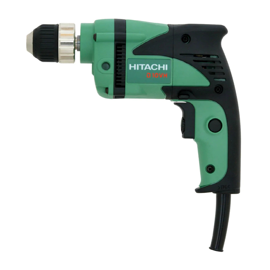
10 mm (3/8”) drills
Hide thumbs
Also See for D 10VC2:
- Handling instructions manual (45 pages) ,
- Handling instructions manual (28 pages) ,
- Handling instructions manual (24 pages)

Related Manuals for Hitachi D 10VC2


Summary of Contents for Hitachi D 10VC2
- Page 1 MODELS D 10VC2 D 10VH POWER TOOLS TECHNICAL DATA 10 mm (3/8”) DRILLS D 10VC2 D 10VH SERVICE MANUAL LIST Nos. D 10VC2: 0199 DEC. 2002 D 10VH: E101 SPECIFICATIONS AND PARTS ARE SUBJECT TO CHANGE FOR IMPROVEMENT...
- Page 2 REMARK: Throughout this TECHNICAL DATA AND SERVICE MANUAL, a symbol(s) is(are) used in the place of company name(s) and model name(s) of our competitor(s). The symbol(s) utilized here is(are) as follows: Competitors Symbols Utilized Company Name Model Name 6410 MAKITA 6408 GBM10RE BOSCH...
-
Page 3: Table Of Contents
8-3. Wiring Diagram ........................... 14 8-4. Internal Wire Arrangement and Wiring Work ................15 8-5. Insulation Tests ........................... 18 8-6. No-Load Current Value ....................... 18 9. STANDARD REPAIR TIME (UNIT) SCHEDULES ..............19 Assembly Diagram for D 10VC2 Assembly Diagram for D 10VH... -
Page 4: Product Name
For the Model D 10VC2, special emphasis was placed on making it lightweight at designing. While the motor size of the Model D 10VC2 is equivalent to that of the previous Model D 10VC, the maximum output is about 15% greater than that of the Model D 10VC. -
Page 5: Selling Points
(1) Compact and lightweight To make both the Models D 10VC2 and D 10VH compact is the first priority at designing because it is a merit of the previous Model D 10VC. Entire length of the Models D 10VC2 and D 10VH is 238 mm and the center height is 26 mm. -
Page 6: Specifications
5. SPECIFICATIONS 5-1. Specifications Model D 10VC2 D 10VH Capacities Steel Twist bit 10 mm (3/8") Wood Flat spade bit 25 mm (1") Auger bit 16 mm (5/8") Drill chuck Mount type UNF 3/8" - 24 Capacity 10 mm (3/8") -
Page 7: Optional Accessories
For customers continued safety and electrical shock protection, installing Hook (A) on this drill should ONLY be performed by a HITACHI AUTHORIZED SERVICE CENTER. For attaching procedure of Hook (A), refer to "Attaching Hook (A)" in this manual. Side handle (Code No.981205) -
Page 8: Comparisons With Similar Products
6. COMPARISONS WITH SIMILAR PRODUCTS 6-1. Specification Comparisons < D 10VC2 > HITACHI D 10VC D 10VC2 10 (3/8") 10 (3/8") 10 (3/8") Steel mm (in.) 10 (3/8") 10 (3/8") Capacities 16 (5/8") 25 (1") 25 (1") Wood mm (in.) 25 (1") -
Page 9: Drilling Speed Comparisons
6-2. Drilling Speed Comparisons Drilling speed depends on the operating conditions. The following test results are based on actual factory tests, and should be used as a reference only. < D 10VC2> Twist bit Test material: Mild steel Thrust: 300 N... - Page 10 < D 10VH > Twist bit Test material: Mild steel Thrust: 300 N D 10VH D 10VC 10 mm dia. 6.5 mm dia. Bit dia. (mm) Auger bit Test material: Western hemlock 3000 2500 2000 D 10VH D 10VC 1500 1000 15 mm dia.
-
Page 11: Precautions In Sales Promotion
7. PRECAUTIONS IN SALES PROMOTION In the interest of promoting the safest and most efficient use of the Models D 10VC2 and D 10VH Drills by all of our customers, it is very important that at the time of sales the salesperson carefully ensures that the buyer seriously recognizes the importance of the contents of the Handling Instructions, and fully understands the meaning of the precautions listed on the Caution Plate attached to each tool. -
Page 12: Attaching Hook (A)
The numbers in the descriptions below correspond to the item numbers in the Parts List and exploded assembly diagram. The [Bold] numbers are for the Model D 10VC2, and the <Bold> numbers for the Model D 10VH. (1) Loosen the Tapping Screw (W/Flange) D4 x 20 (Black) [23] <21> and remove the Handle Cover [24] <22>. -
Page 13: Precautions In Disassembly And Reassembly
8. PRECAUTIONS IN DISASSEMBLY AND REASSEMBLY The numbers in the descriptions below correspond to the item numbers in the Parts List and exploded assembly diagram. The [Bold] numbers are for the Model D 10VC2 and the <Bold> numbers for the Model D 10VH. 8-1. Disassembly 8-1-1. - Page 14 (4) Removal of the armature ass'y from the inner cover As illustrated in Fig. 4, support the Inner Cover [11] <11> with a tubular jig, and push down on the top of the pinion of the Armature [13] <13>. Push Inner Cover [11] <11>...
- Page 15 8-1-2. Removal of the drill chuck The Drill Chuck [2] <2> is secured to the Spindle [4] <4> with 3/8"-24 UNF (Right hand). Hold the Spindle [4] <4> with the open-end wrench secured to the vise as shown in Fig. 5. Mount the pipe to the hex.
-
Page 16: Reassembly
8-2. Reassembly Reassembly can be accomplished by following the disassembly procedures in reverse. However, special attention should be given to the following items. 8-2-1. Internal wire arrangement (1) Arrange the internal wires according to "8-4. Internal Wire Arrangement and Wiring Work". (2) Be careful not to catch the internal wires when mounting the handle cover. -
Page 17: Wiring Diagram
8-3. Wiring Diagram (1) For products with noise suppressor Choke coil White Stator Black or brown Gray Blue Cord ass'y Noise suppressor Brown Stator Black White or blue Choke coil Speed control switch Reversing switch (2) For products without noise suppressor Stator Black or brown Gray... -
Page 18: Internal Wire Arrangement And Wiring Work
8-4. Internal Wire Arrangement and Wiring Work A. Internal wire arrangement (1) For products with noise suppressor Natural (Noise suppressor) Black (Stator) Blue White (Stator) (Choke coil) Brown Gray (Stator) (Choke coil) Red (Stator) White (Stator) Gray (Stator) Red (Stator) White or blue Black or brown (Cord) - Page 19 (2) For products without noise suppressor Black (Stator) Blue (Lead wire) White (Stator) Brown Gray (Stator) (Lead wire) Red (Stator) White (Stator) Gray (Stator) Red (Stator) White or blue Black or brown (Cord) (Cord) Cord Put the CB terminal between (a) and (b). Brush holder Carbon brush --- 16 ---...
- Page 20 B. Switch connection (1) Wiring of reversing switch Blue Black (Choke coil/ Lead wire) (Stator) White Brown (Stator) (Choke coil/ Lead wire) (2) Wiring of speed control switch Black or brown White or blue (Cord) (Cord) Red (Stator) Gray (Stator) Noise suppressor --- 17 ---...
-
Page 21: Insulation Tests
8-5. Insulation Tests On completion of reassembly after repair, measure the insulation resistance and conduct the dielectric strength test. Insulation resistance: 7 MΩ or more with DC 500 V Megohm Tester Dielectric strength: AC 4,000 V/1 minute, with no abnormalities 220 V --- 240 V (and 110 V for U.K. products) AC 2,500 V/1 minute, with no abnormalities 110 V --- 127 V (except U.K. -
Page 22: Standard Repair Time (Unit) Schedules
9. STANDARD REPAIR TIME (UNIT) SCHEDULES Variable 60 min. MODEL Fixed Work Flow D 10VC2 D 10VH Switch Cord Handle Cover Housing Stator General Assembly Armature Ball Bearing (608VV) x 2 Inner Cover Gear Cover Gear Spindle Drill Chuck Ball Bearing... - Page 23 LIST NO. 0199 ELECTRIC TOOL PARTS LIST DRILL 2002 • • Model D 10VC2 (E1)
- Page 24 PARTS D 10VC2 ITEM CODE NO. DESCRIPTION REMARKS USED 980-057 CHUCK WRENCH 10TL2 1 FOR HKG, NZL, FIJ, HOL 950-292 DRILL CHUCK 10TLRA 1 INCLUD. 1 FOR HKG, NZL, FIJ, HOL 312-516 1 EXCEPT FOR NZL, FIJ DRILL CHUCK 10TLRD-N (W/O CHUCK WRENCH)
- Page 25 STANDARD ACCESSORIES D 10VC2 ITEM CODE NO. DESCRIPTION REMARKS USED 321-635 CASE FOR SIN, MAL, SRI, NZL, FIJ, GBR, FRA, FIN, NOR OPTIONAL ACCESSORIES ITEM CODE NO. DESCRIPTION REMARKS USED 982-593 HOOK 321-612 HOOK (A) 981-205 SIDE HANDLE FOR M10...
- Page 26 D 10VC2 ITEM CODE NO. DESCRIPTION REMARKS USED --- 4 --- 12 -- 02 Printed in Japan (021210N)
- Page 27 LIST NO. E101 ELECTRIC TOOL PARTS LIST DRILL 2002 • • Model D 10VH (E1)
- Page 28 HANDLE COVER 321-632 SWITCH (1P PILLAR TYPE) 321-628 PUSHING BUTTON 999-041 CARBON BRUSH (1 PAIR) 955-203 BRUSH HOLDER HITACHI LABEL 984-750 TAPPING SCREW (W/FLANGE) D4X16 937-631 CORD CLIP 953-327 CORD ARMOR D8.8 500-240Z CORD --- 2 --- * ALTERNATIVE PARTS...
-
Page 29: Standard Accessories
STANDARD ACCESSORIES D 10VH ITEM CODE NO. DESCRIPTION REMARKS USED 321-635 CASE OPTIONAL ACCESSORIES ITEM CODE NO. DESCRIPTION REMARKS USED 982-593 HOOK 321-612 HOOK (A) 981-205 SIDE HANDLE FOR M10 12 -- 02 * ALTERNATIVE PARTS --- 3 -- -... - Page 30 D 10VH ITEM CODE NO. DESCRIPTION REMARKS USED --- 4 --- 12 -- 02 Printed in Japan (021210N)