Table of Contents
Advertisement
Quick Links
DIGITAL CONTROL AMPLIFIER
C-AX10
THIS MANUAL IS APPLICABLE TO THE FOLLOWING MODEL(S) AND TYPE(S).
Model
Type
C-AX10
KU/CA
NY
CONTENTS
1. SAFETY INFORMATION ...................................... 2
2. EXPLODED VIEWS AND PARTS LIST ............... 3
4. PCB CONNECTION DIAGRAM ......................... 50
5. PCB PARTS LIST ............................................... 76
6. ADJUSTMENT .................................................... 83
7. GENERAL INFORMATION ................................ 84
7.1 DIAGNOSIS .................................................. 84
7.1.1 TEST MODE ........................................... 84
7.1.2 TROUBLESHOOTING ........................... 85
PIONEER ELECTRONIC CORPORATION
PIONEER ELECTRONICS SERVICE, INC. P.O. Box 1760, Long Beach, CA 90801-1760, U.S.A.
PIONEER EUROPE NV Haven 1087, Keetberglaan 1, 9120 Melsele, Belgium
PIONEER ELECTRONICS ASIACENTRE PTE. LTD. 253 Alexandra Road, #04-01, Singapore 159936
c
PIONEER ELECTRONIC CORPORATION 2000
Power Requirement
AC120V
AC230V
4-1, Meguro 1-chome, Meguro-ku, Tokyo 153-8654, Japan
DOLBY
D I G I T A L
7.1.3 POWER ON SEQUENCE ...................... 86
7.1.4 DISASSEMBLY ...................................... 90
7.1.5 PCB LAYOUT ......................................... 95
7.2 PARTS .......................................................... 96
7.2.1 IC ............................................................ 96
7.2.2 DISPLAY ............................................... 109
7.3 REMOTE CONTROL UNIT ........................ 110
8. PANEL FACILITIES AND SPECIFICATIONS ..... 113
T - ZZR JULY 2000 Printed in Japan
ORDER NO.
RRV2327
Remarks
Advertisement
Table of Contents

Related Manuals for Pioneer C-AX10


Summary of Contents for Pioneer C-AX10
-
Page 1: Table Of Contents
PIONEER ELECTRONIC CORPORATION 4-1, Meguro 1-chome, Meguro-ku, Tokyo 153-8654, Japan PIONEER ELECTRONICS SERVICE, INC. P.O. Box 1760, Long Beach, CA 90801-1760, U.S.A. PIONEER EUROPE NV Haven 1087, Keetberglaan 1, 9120 Melsele, Belgium PIONEER ELECTRONICS ASIACENTRE PTE. LTD. 253 Alexandra Road, #04-01, Singapore 159936 PIONEER ELECTRONIC CORPORATION 2000 T –... -
Page 2: Safety Information
The use of a substitute replacement component which does Leakage 0.5mA current Device not have the same safety characteristics as the PIONEER tester under recommended replacement one, shown in the parts list in test this Service Manual, may create shock, fire, or other hazards. -
Page 3: Exploded Views And Parts List
Warranty Card See Contrast table (2) Mirror Mat Bag VHL1004 Front Pad AHA9016 (2) CONTRAST TABLE C-AX10/KU/CA and NY are constructed the same except for the following : Part No. Mark No. Symbol and Description Remarks KU/CA Type NY Type... - Page 4 C-AX10 2.2 EXTERIOR 34 89 34 NY Type NY Type Only Only KU/CA Type 72 67 Only Refer to section "2.3 FRONT PANEL SECTION". KU/CA Type Only...
- Page 5 C-AX10 (1) EXTERIOR PARTS LIST Mark No. Description Part No. Mark No. Description Part No. DSP Assy See Contrast table (2) PCB Base RNE1849 SG Assy AWX7444 Washer ABE-053 AUDIO A Assy AWX7530 J1401 14P FFC/30V ADD7130 AUDIO B Assy AWX7531 (DIGITAL I/O CN1401↔DSP CN1601)
- Page 6 C-AX10 (2) CONTRAST TABLE C-AX10/KU/CA and NY are constructed the same except for the following : Part No. Mark No. Symbol and Description Remarks KU/CA Type NY Type DSP Assy AWK7589 AWK7590 AC Assy AWX7298 AWX7536 PS Assy AWX7299 AWX7537...
- Page 7 C-AX10 2.3 FRONT PANEL SECTION Tighten a screw of No. 56 from the left side.
- Page 8 Rotary Knob M AAB7203 FL Panel S AAK9052 Rotary Knob L AAB7204 Panel Base AMB9021 Rotary Knob S AAB7200 Rubber Spacer AEB7182 PIONEER Badge G PAN1377 Magnet AMF7004 Screw BBZ30P080FCC Spacer Film C AEC7257 Screw BPZ30P080FMC Magnet Cover AAK9045 Screw...
- Page 9 C-AX10...
-
Page 10: Block Diagram And Schematic Diagram
C-AX10 3. BLOCK DIAGRAM AND SCHEMATIC DIAGRAM 3.1 BLOCK DIAGRAM 3.1.1 I/O BLOCK DIGITAL I/O ASSY DSP ASSY DIGITAL INPUT 1. COAX (MASTER) DIGITAL IC1603 2. COAX INPUT CS8414-CS /OUTPUT Hi-bit 3. COAX SELECTOR IC1610 IC1613 4. OPT IC1404,IC1405 PD0236AM... -
Page 11: Display Assy
C-AX10 AUDIO A ASSY AUDIO B ASSY DIGITAL FILTER DAC VR F L (HIGH) IC501 IC1701 IC1702 IC1703 IC901 PCM1704U-J F L (LOW) XCD56362PV100 XCD56362PV100 SM5847AF AD7564BR IC502 PCM1704U-J DAC VR DIGITAL FILTER F R (HIGH) IC601 IC1001 IC1801 IC1802... - Page 12 C-AX10 3.1.2 POWER SUPPLY BLOCK PS ASSY AC ASSY FRAD ASSY AUDIO A ASSY AUDIO B ASSY...
- Page 13 C-AX10 3.1.3 A/D BLOCK...
- Page 14 C-AX10 3.1.4 D/A BLOCK (AUDIO A ASSY)
- Page 15 C-AX10 3.1.5 D/A BLOCK (AUDIO B ASSY)
- Page 16 C-AX10 3.1.6 DIGITAL SIGNAL BLOCK DIGITAL I/O ASSY DSP ASSY...
- Page 17 C-AX10 to D/A SECTION...
- Page 18 C-AX10 3.1.7 µ-COM PORT BLOCK Hi-bit Hi-bit FRONT Hi-bit...
- Page 19 C-AX10 DSP ASSY AUDIO B ASSY AUDIO A ASSY VOLUME ASSY DISPLAY ASSY...
-
Page 20: Overall Wiring Diagram
C-AX10 3.2 OVERALL WIRING DIAGRAM AC120V 60Hz (KU/CA) AC230V 50/60Hz (NY) AC POWER CORD DIGITAL KU/CA : ADG7028 NY : ADG7029 I/O ASSY (AWX7533) 1/6- FU101 (4A 125V) KU/CA : VEK1023 DSP ASSY NY : REK-106 AC ASSY (KU/CA : AWK7589) - Page 21 C-AX10 Note : When ordering service parts, be sure to refer to "EXPLODED VIEWS and PARTS LIST" or "PCB PARTS LIST". GCLK(S) REAR_WCLK VC18L1 AUDIO A ASSY VE18L1 VC18L2 (AWX7530) VE18L2 C/L_WCLK C/L_BCLK AUDIO B ASSY VC18R1 (AWX7531) VE18R1 VC18R2...
- Page 22 C-AX10 3.3 DIGITAL I/O ASSY : The power supply is shown with the marked box. : DIGITAL AUDIO SIGNAL ROUTE DIGITAL I/O ASSY : DIGITAL (PDIF) AUDIO SIGNAL ROUTE (AWX7533) +5.1V +8.1V VTL1099...
- Page 23 C-AX10 3.4 AC and PS ASSYS • NOTE FOR FUSE REPLACEMENT AC ASSY (KU/CA : AWX7298) FOR CONTINUED PROTECTION CAUTION - (NY : AWX7536) AGAINST RISK OF FIRE. REPLACE WITH SAME C101, C102 KU/CA : ACE7014 : 0.01 TYPE AND RATINGS ONLY.
- Page 24 C-AX10 3.5 SG and FRAD (1/3) ASSYS FRAD ASSY (AWX7532) HEAT SINK +25.4V PCB BINDER PCB BINDER VEF1040 VEF1040 -25.4V -19.8V +17.8V +11.8V (3.15A) +10V -10.3V CN1402...
- Page 25 C-AX10 : The power supply is shown with the marked box. +3.3V CN2901 +5.6V BINDER VEF1040 CN904 CN902 CN903 +5.3V CN1004 CN1002 CN2107 -5.5V CN1003 CAUTION : FOR CONTINUED PROTECTION AGAINST RISK OF FIRE. CAUTION : FOR CONTINUED PROTECTION AGAINST REPLACE ONLY WITH SAME TYPE NO.
- Page 26 C-AX10 3.6 FRAD ASSY (2/3) FRAD ASSY (AWX7532) C1171 DTL1019 470p ACE7018 F1101 DTL1019 DTF1070 DTL1019 DTL1019 DTL1019 DTL1019 DTL1019 C1172 470p DTL1019 ACE7018 PCB BINDER VEF1040 RY1101 - RY1109 : VSR1008 D1101 - D1118 : 1SS355 PCB BINDER VEF1040...
- Page 27 C-AX10 : ANALOG AUDIO SIGNAL ROUTE (FRONT) : ANALOG AUDIO SIGNAL ROUTE (Multi) L1202 DTL1019 ANALOG IN +3.3V L1204 DTL1019 PCB BINDER VEF1040 G+-6 INPUT GAIN G-06 ANALOG 3 XPHN +5.0V +5.0V LINE +5.0V PHONO +5.0V VCLK+3 ANALOG IN : 0V...
- Page 28 C-AX10 3.7 FRAD (3/3) and CRAD ASSYS CRAD ASSY (AWX7535) FRAD ASSY (AWX7532) L1301 DTL1019 L1302 DTL1019 PCB BINDER VEF1040 L1303 DTL1019 L1304 DTL1019...
- Page 29 C-AX10 : ANALOG AUDIO SIGNAL ROUTE (Multi) : The power supply is shown with the marked box. J403 J2903 ADX7270 CN1202...
- Page 30 C-AX10 3.8 DSP ASSY (1/6) 4/6, 5/6 IC SOCKET (IC9001) IC160-0324-230...
- Page 31 C-AX10 DSP ASSY (KU/CA : AWK7589) : The power supply is shown with the marked box. (NY : AWK7590) KU/CA ONLY NY ONLY IC SOCKET (IC9002) IC160-0324-230...
- Page 32 C-AX10 3.9 DSP ASSY (2/6) PDIF : +5V OTHERS : 0V ANALOG IN : 0V DIGITAL IN : +5V DIGITAL IN (fs=48.44k) Hi-Bit ON : +5V OFF : 0V L1603 L1604 ANALOG IN , DIGITAL IN(fs=96.88k) : +5V...
- Page 33 C-AX10 DSP ASSY (KU/CA : AWK7589) (NY : AWK7590) : DIGITAL AUDIO SIGNAL ROUTE : ANALOG AUDIO SIGNAL ROUTE : DIGITAL (PDIF) AUDIO SIGNAL ROUTE : AUDIO SIGNAL ROUTE...
- Page 34 C-AX10 3.10 DSP ASSY (3/6) DSP ASSY (KU/CA : AWK7589) (NY : AWK7590) F1508 DTF1070...
- Page 35 C-AX10 : AUDIO SIGNAL ROUTE +3.3V +3.3V...
- Page 36 C-AX10 3.11 DSP ASSY (4/6) DSP ASSY (KU/CA : AWK7589) (NY : AWK7590)
- Page 37 C-AX10 : AUDIO SIGNAL ROUTE...
- Page 38 C-AX10 3.12 DSP ASSY (5/6) DSP ASSY (KU/CA : AWK7589) (NY : AWK7590)
- Page 39 C-AX10...
- Page 40 C-AX10 3.13 DSP ASSY (6/6) PDIF (192k) : +5V OTHERS : 0V...
- Page 41 C-AX10 DSP ASSY (KU/CA : AWK7589) : AUDIO SIGNAL ROUTE (NY : AWK7590) L1701-L1704 : VTL1083 L1704 L1706 L1703 VTL1105 L1702 L1701 L1705 VTL1105 L1801-L1804 : VTL1083 L1804 L1806 L1803 VTL1105 L1802 L1801 L1805 VTL1105 TC7WH08FU TC7WH08FU...
- Page 42 C-AX10 3.14 AUDIO A ASSY AUDIO A ASSY (AWX7530) Base of Q901-Q904 PCB BINDER FIR/IIR NORMAL VEF1040 2ch MULTI 2ch MULTI 2DIV X2CB 0V X2NR 0V XDIV PCB BINDER VEF1040 PCB BINDER VEF1040 R905 PCB BINDER VEF1040...
- Page 43 C-AX10 : AUDIO SIGNAL ROUTE PCB BINDER VEF1040 DIRECT 2ch/ALL :0V OFF : 5V UNLOCK :0V NORMAL :5V UNLOCK :0V MULTI DIRECT ALL :0V 2ch/OFF : 5V : The power supply is shown with the marked box.
- Page 44 C-AX10 3.15 AUDIO B ASSY AUDIO B ASSY (AWX7531) PCB BINDER VEF1040 BINDER BINDER R1007 PCB BINDER VEF1040...
- Page 45 C-AX10 PCB BINDER VEF1040 : The power supply is shown with the marked box.
- Page 46 C-AX10 3.16 DISPLAY, VOLUME, ENC A, INPUT SW and ENC B ASSYS DISPLAY ASSY (AWX7305) DIRECT : 0.7V MIDNIGHT : 1.4V Hi-Bit : 2.1V : 2.8V 95/48 : 3.6V : 0V : 1V : 1.9V NORM : 3.8V FL ON...
- Page 47 C-AX10 DISPLAY ASSY INPUT SW ASSY S2202 : PARAMETER CHECK S2213 : DIGITAL NR S2301 : INPUT SELECTOR S2203 : Ÿ/DTS S2214 : SYSTEM SETUP S2204 : DIRECT S2215 : REC SELECTOR (DIGITAL) ENC A ASSY S2205 : TONE S2216 : fs (96k/48k)
- Page 48 C-AX10 WAVEFORMS Note : The encircled numbers denote measuring point in the schematic diagram. Measurement condition ; No. 1-1 : DIGITAL OUT, fs = 96kHz No. 7 and 9 : ANALOG IN No. 1-2 : DIGITAL OUT, fs = 48kHz (data support to 16 through 24 bit.)
- Page 49 C-AX10 AUDIO A ASSY DAC output (f=1kHz) Front DF output Center DSP input (IC503-pin 1) (IC1703-pin 4 :WCKO, pin 5 :BCKO, (IC1501-pin 12 :FST, pin 14 :SCKT, V: 5V/div. H: 0.2msec/div. pin 2 :DOR) pin 10 :SDI1) V: 5V/div. H: 0.2µsec/div.
-
Page 50: Pcb Connection Diagram
C-AX10 4. PCB CONNECTION DIAGRAM 4.1 AC, PS ASSYS AC ASSY (ANP7293-A) AC INLET T401 T301 ASSY CN405 – CN407 PS ASSY IC203 IC201 IC204 Q201 IC202 CN301 IC205 IC206 (ANP7293-A) J2202 SIDE A... - Page 51 C-AX10 NOTE FOR PCB DIAGRAMS : 1. Part numbers in PCB diagrams match those in the schematic 3. The parts mounted on this PCB include all necessary parts for diagrams. several destinations. 2. A comparison between the main parts of PCB and schematic For further information for respective destinations, be sure to diagrams is shown below.
- Page 52 C-AX10 4.2 DIGITAL I/O ASSY DIGITAL I/O ASSY CN1601 J301- pins 1, 2 (ANP7292-B) SIDE A...
- Page 53 C-AX10 DIGITAL I/O ASSY IC1406 IC1404 IC1401 IC1405 IC1402 IC1403 (ANP7292-B) SIDE B...
- Page 54 C-AX10 4.3 SG, FRAD ASSYS CN2101 CN1602 J2903 FRAD ASSY J2901 IC1106 IC1202 IC1204 IC1203 IC412 IC1101 IC1201 IC1103 IC1105 IC1102 IC41 IC1104 SIDE A...
- Page 55 C-AX10 CN2901 T401 CN1003 CN903 CN902 CN904 CN1002 CN1004 CN1402 IC304 IC304 CN2107 CN2104 (ANP7292-B) T401 T401 J201 IC412 IC413 IC1405 – IC1409 IC402 Q416 Q402 Q401 IC404 IC401 IC410 Q407 Q417 Q418 IC306 IC304 IC411 IC403 IC302 IC305 IC303...
- Page 56 C-AX10 FRAD ASSY Q406 Q408 Q404 Q405 Q419 Q403 Q421 Q420 Q409 Q422 SG ASSY...
- Page 57 C-AX10 (ANP7292-B) IC1105 IC1203 IC1204 IC1202 IC1201 Q1108 Q1201 Q1109 Q1104 Q1106 Q1103 Q1107 Q1101 Q1102 Q1301 Q1302 Q1105 SIDE B...
- Page 58 C-AX10 4.4 CRAD ASSY CN1202 CRAD ASSY IC2802 IC2803 IC2801 J403 CN1301 IC2702 IC2703 IC2701 (ANP7292-B) SIDE A...
- Page 59 C-AX10 CRAD ASSY IC2804 Q2801 Q2802 Q2702 Q2701 IC2704 (ANP7292-B) SIDE B...
- Page 60 C-AX10 4.5 DSP ASSY J1201 CN1201 J902 DSP ASSY CN1401 IC1505 IC1612 IC1611 IC1507 IC1509 IC1702 IC19 IC1501 IC1510 IC1701 IC1513 IC1506 IC1511 SIDE A IC1512 IC1607 IC1603 IC1602 IC1616 IC1613...
- Page 61 C-AX10 CN1001 CN901 J1002 CN2201 J301 (ANP7290-E) IC1702 IC1903 IC1704 IC1804 IC2003 IC2116 IC2109 Q2101 IC1703 IC1803 IC1701 IC1802 IC9003 IC2102 IC1801...
- Page 62 C-AX10 DSP ASSY IC2104 IC2113 IC2108 IC2107 IC2002 IC2110 IC9002 IC2118 IC2001 IC2114 IC2106 IC2101 SIDE B IC9001 IC2115...
- Page 63 C-AX10 (ANP7290-E) IC1902 IC1504 IC1508 IC1502 IC1503 IC1608 IC1609 IC2111 IC1901 IC2112 IC1625 IC1610 IC1632 IC1605 IC2103 IC1624 IC1621 IC1615 IC1606 IC1614 IC1601 IC1622 IC1620 IC1623 IC1619 IC1618...
- Page 64 C-AX10 4.6 AUDIO A ASSY CN403-pins 1 to 7 CN1703 AUDIO A ASSY CN403-pins 10,11 IC903 IC702 IC701 IC502 IC501 IC704 IC703 IC504 IC503 SIDE A...
- Page 65 C-AX10 CN2102 (ANP7291-D) CN403-pins 8,9 IC501 IC705 IC707 IC503 IC706 IC902 IC708 IC505 IC901 IC507 IC506 IC508...
- Page 66 C-AX10 AUDIO A ASSY Q908 Q907 Q903 Q910 Q912 Q902 Q901 SIDE B...
- Page 67 C-AX10 (ANP7291-D) Q903 Q901 Q905 Q906 Q904...
- Page 68 C-AX10 4.7 AUDIO B ASSY CN404-pins 1 to 7 CN1803 AUDIO B ASSY CN404-pins 10,11 IC1003 IC802 IC801 IC602 IC601 IC804 IC803 IC604 IC603 SIDE A...
- Page 69 C-AX10 CN2103 (ANP7291-D ) CN404-pins 8,9 IC601 IC805 IC808 IC603 IC806 IC1002 IC807 IC605 IC1001 IC607 IC606 IC608...
- Page 70 C-AX10 AUDIO B ASSY Q1008 Q1003 Q1007 Q1013 Q1015 Q1002 Q100 Q1011 SIDE B...
- Page 71 C-AX10 (ANP7291-D) Q1003 Q1007 Q1001 Q1005 Q1006 Q1004 Q1009...
- Page 72 C-AX10 4.8 DISPLAY, VOLUME, ENC A, INPUT SW, ENC B ASSYS DISPLAY ASSY CN202 ENC A ASSY (ANP7293-A) FRONT PANEL FRONT PANEL INPUT SW ASSY (ANP7293-A) SIDE A J L M...
- Page 73 C-AX10 CN2108 (ANP7293-A) ENC B ASSY FRONT PANEL (ANP7293-A) VOLUME ASSY (ANP7293-A) J K N...
- Page 74 C-AX10 IC2202 IC2203 DISPLAY ASSY ENC B ASSY VOLUME ASSY (ANP7293-A) (ANP7293-A) SIDE B J K N...
- Page 75 C-AX10 Q2203 IC2201 Q2202 Q2201 Q2204 Q2205 Q2206 (ANP7293-A) ENC A ASSY (ANP7293-A) INPUT SW ASSY (ANP7293-A) J L M...
-
Page 76: Pcb Parts List
C-AX10 Mark No. Description Part No. Mark No. Description Part No. 5. PCB PARTS LIST • NOTES: Parts marked by "NSP" are generally unavailable because they are not in our Master Spare Parts List. • mark found on some component parts indicates the importance of the safety factor of the part. - Page 77 C-AX10 Mark No. Description Part No. Mark No. Description Part No. PCB PARTS LIST FOR C-AX10/KU/CA UNLESS OTHERWISE NOTED Mark No. Description Part No. Mark No. Description Part No. OTHERS DIGITAL I/O ASSY H101,H102 FUSE CLIP AKR1004 SEMICONDUCTORS CN102 2P VH CONNECTOR...
- Page 78 C-AX10 Mark No. Description Part No. Mark No. Description Part No. C1202 CCSQCH5R0C50 FRAD ASSY C1152 CEGA100M50 C1125-C1128 CEGA220M50 SEMICONDUCTORS C1119-C1122,C1159,C1160 CEGANP470M16 IC304,IC411-IC413 AEK7006 C303,C430,C435,C436 CEHAZL470M25 IC405 AEK7010 IC403 AEK7016 C413,C414,C438 CEHAZL561M35 IC408 AEK7023 C1117,C1118,C428,C445,C446 CENA100M50 IC1105 AK5393VS C305,C405,C406,C425 CENA1R0M50...
- Page 79 C-AX10 Mark No. Description Part No. Mark No. Description Part No. OTHERS RESISTORS J405 CONNECTOR ASSY 1P ADX7265 R2725-R2728,R2825-R2828 RN1/10SC51R0D J401 CONNECTOR ASSY 1P ADX7266 R2733-R2736,R2833-R2836 RN1/10SE1002D J1201 ADX7267 R2709,R2710,R2717,R2718 RN1/10SE1101D CONNECTOR ASSY 12P J403 CONNECTOR ASSY 8P ADX7269 R2809,R2810,R2817,R2818...
- Page 80 C-AX10 Mark No. Description Part No. Mark No. Description Part No. IC1618 TC9246F C1516,C1640,C1665,C1711,C1738 CKSQYB474K16 IC1501,IC1613,IC1701,IC1702 XCD56362PV100 C1811,C1838 CKSQYB474K16 IC1801,IC1802 XCD56362PV100 C1503,C1505-C1507,C1513,C1517 CKSRYB103K50 Q2101 2SA1037K C1519-C1524,C1526-C1530 CKSRYB103K50 D2106 1SS254 C1532,C1533,C1540,C1543,C1547 CKSRYB103K50 D1601,D1602,D2101,D2102 1SS355 C1604,C1605,C1609,C1610 CKSRYB103K50 D2104,D2105 1SS355 C1633,C1634,C1636-C1638 CKSRYB103K50 D1701,D1702,D1801,D1802...
- Page 81 C-AX10 Mark No. Description Part No. Mark No. Description Part No. C765,C766,C771-C774 CKSQYB103K50 OTHERS C507,C508,C559,C560 CKSQYB104K25 IC9001,IC9002 IC SOCKET IC160-0324-230 C707,C708,C759,C760 CKSQYB104K25 J2102 CONNECTOR ASSY 3P ADX7348 C916,C917 CKSQYB104K25 X1501 CRYSTAL RESONATOR ASS7023 C501,C502,C523,C524 CKSQYB473K50 (20MHz) X2101,X2102 ASS7026 C527,C528,C537,C538 CKSQYB473K50 CERAMIC RESONATOR (7.7MHz)
- Page 82 C-AX10 Mark No. Description Part No. Mark No. Description Part No. Q1001-Q1009,Q1011,Q1013,Q1015 DTC124EK R621-R624,R645,R646 RN1/10SE1001D D1001-D1024 1SS355 R817,R818,R823,R824 RN1/10SE1001D R847-R849,R851 RN1/10SE1001D COILS AND FILTER R1004 RN1/10SE1102D R615,R616,R809-R812 RN1/10SE1201D F1001 CHIP BEAD DTF1070 L1001,L1002,L601-L604 RTF1167 R629,R630,R825,R826 RN1/10SE1501D NOISE FILTER R625,R626,R821,R822 RN1/10SE1801D...
-
Page 83: Adjustment
C-AX10 Mark No. Description Part No. Mark No. Description Part No. OTHERS ENC B ASSY CN2201 FFC CONNECTOR 28P 28FMZ-ST SWITCH V2201 FL TUBE AAV7065 J2202 CONNECTOR ASSY 4P ADX7275 S2501 ASX7022 J2203 ADX7276 CONNECTOR ASSY 12P 2201 GP1U27X REMOTE RECEIVER UNIT... -
Page 84: General Information
C-AX10 7. GENERAL INFORMATION (5) Master VOLUME operation confirmation Enter the operation confirmation mode of master VOLUME when 7.1 DIAGNOSIS pressing the "NETWORK SETUP + DIGITAL NR" keys during test mode. 7.1.1 Test Mode Switch as follows whenever pressing the "NETWORK+DIGITAL NR"... -
Page 85: Troubleshooting
C-AX10 7.1.2 Troubleshooting Firstly confirm that connection of each connector and FFC are correctly. L ch : #1700- R ch : #1800- Do lock it Is master clock Digital Analog input or (IC2102-pin 19) (IC1703-pin 16) digital input ? normal ? -
Page 86: Power On Sequence
C-AX10 7.1.3 Power ON Sequence Main Microcomputer (1/2) (IC2109) Destination check AC check Port 70 (I/O ST) Destination KU/CA Distinction of the speaker distance "m" and "feet". Hardware register setting of system controller Use port 70 as a destination port only in the power ON state, and use it as a strobe port of the expansion IC in normal state. - Page 87 C-AX10 Main Microcomputer (2/2) (IC2109) DSP µCOM RESET Port 8 (RST) Initial setting of DSP µCOM Port 12 (CS) communication Port 14 (REQ) : H Each SW relay setting of output side IC2108-port 4, IC2107-port 11 IC2108-port 14 OUTPUT MODE...
- Page 88 C-AX10 DSP Control Microcomputer (IC2102) • POWER ON From the system control microcomputer (IC2109) • Cancel the reset (IC2102-pin 12) : L to H Start • Data reception of each setting Legato DSP IC1613 setup Transmit the program and coefficient...
- Page 89 C-AX10 • Input switch (Analog to Digital) • Input switch (Digital to Analog) Receive a switching data from Receive a switching data from the system control microcomputer the system control microcomputer Start Start (IC2109). (IC2109). Front ch : IC1703 and IC1803...
-
Page 90: Disassembly
C-AX10 7.1.4 Disassembly Top Plate, Side Alum. L and R AUDIO A ASSY ×6 ×4 ×3 ×4 ×3 It is easy to remove it by Top Plate lifting front side of the AUDIO A ASSY. ×2 ×2 Stand the AUDIO A ASSY, and tighten a screw from the Rear Mole Side Alum. - Page 91 C-AX10 AUDIO B ASSY Stand the AUDIO B ASSY and diagnose it. Remove the AUDIO A ASSY. (AUDIO B ASSY works even if removes the AUDIO A ASSY.) ×4 VOLUME ASSY Hook it on a cut part of the Rear Panel.
- Page 92 C-AX10 DIGITAL I/O and DSP ASSYS ×8 (DIGITAL I/O ASSY) When diagnosing the analog input and output system All diagnoses are completed when connects the DIGITAL Hook it on a cut part of I/O ASSY. the Rear Panel. ×2 (DSP ASSY) Power Cord ×2...
- Page 93 C-AX10 Styling in installation (DSP ASSY) ×3 Caution: Perform styling so that each wire does not come near. Bind Bind two pairs of wires Clamp the wires to in the player. connect the DIGITAL Clamp two wires I/O ASSY (Gray and Black).
- Page 94 C-AX10 Power Transformer (T301, T401) ×7 When replacing the Analog Transformer (T401) Remove the DIGITAL I/O ASSY, DSP ASSY and Main Shield. Remove three connectors. Front side CN405 Cut a Binder (ZCA-BK1). ASSY FRAD ASSY ×4 Subchassis B2 CN407 CN406 ×4...
-
Page 95: Pcb Layout
C-AX10 7.1.5 PCB LAYOUT Front Panel Section ×2 DSP ASSY Main Shield Power Trans. Rear Panel ×3 PS ASSY SG ASSY AC ASSY Unhook DIGITAL AUDIO CRAD I/O ASSY A ASSY ASSY Subchassis Side Wall Door Shield Unhook Plate I... -
Page 96: Parts
C-AX10 7.2 PARTS 7.2.1 IC • The information shown in the list is basic information and may not correspond exactly to that shown in the schematic diagrams. • List of IC TC74VHC257FT, TC74VHC244F, TC7WT74FU, TC74VHC4040FT, TC74VHC153FT, TC74VHC157F, TC74VHC163FT, DF1704E, BC4094BCFV, TC7W126FU, AT24C16N-10SI2.5, M30622SFP,... - Page 97 C-AX10 TC7WT74FU (DSP ASSY : IC1605) • D-type Flip Flop with Present and Clear • • Pin Arrangement (Top view) Truth Table INPUTS OUTPUTS FUNCTION CLR PR CLEAR PRESET Qn NO CHANGE X : Don't Care TC74VHC4040FT (DSP ASSY : IC1606, IC1623) •...
- Page 98 C-AX10 TC74VHC153FT (DSP ASSY : IC1614) • Dual 4-channel Multiplexer • • Block Diagram Truth Table SELECT STROBE OUTPUT DATA INPUTS INPUTS X : Don't Care 9 2Y Same as abobe block TC74VHC157F (DSP ASSY : IC1704, IC1804, IC1903, IC2003) •...
- Page 99 C-AX10 TC74VHC163FT (DSP ASSY : IC1620) • Synchronous Presettable 4-bit Counter • • Block Diagram Truth Table LOAD X : Don't Care * : No Change 15 CARRY 13 QB 12 QC 11 QD...
- Page 100 C-AX10 DF1704E (DSP ASSY : IC1902, IC2002) • Digital Filter • Block Diagram IW0 IW1 OW0 OW1 BCKIN BCKO Serial LRCIN 8X Oversampling Input WCKO Digital Filter Output with Fuction Controller MD/CKO MC/LRIP ML/RESV Mode MODE Control MUTE Crystal OSC...
- Page 101 C-AX10 BU4094BCFV (DSP ASSY : IC2101, IC2107, IC2108, IC2118) • Port Expander • • Block Diagram Truth Table PARALLEL SERIAL DATA OUTPUT OUTPUTS OUTPUTS 8-STAGE SERIAL CLOCK STROBE DATA ENABLE SHIFT REGISTER OUTPUT CLOCK 9 Qs ± No Chg. ≠...
- Page 102 C-AX10 TC7W126FU (DSP ASSY : IC2103, IC2114) • Dual Bus Buffer • • Pin Arrangement (Top view) Truth Table INPUTS OUTPUTS X : Don't Care Z : High Impedance AT24C16N-10SI2.5 (DSP ASSY : IC2106) • 2-wire Serial CMOS EEPROM •...
- Page 103 C-AX10 M30622SFP (DSP ASSY : IC2102) • DSP Microcomputer • Pin Function → ← → ← ) t i l l u → → ← − − → l l u ← l a i l e l i t l...
- Page 104 C-AX10 − - / ( − ) - / l i f l i f − − ←...
- Page 105 C-AX10 M38079SFP (DSP ASSY : IC2109) • System Microcomputer • Pin Function t l i f ) ) I n i l ) f f Ω Ω) l l u l l i l l i −...
- Page 106 C-AX10 t i r φ − t i s t i s −...
-
Page 107: Block Diagram
C-AX10 AK5393VS (FRAD ASSY : IC1105 and CRAD ASSY : IC2704, IC2804) • Enhanced Dual-bit 108kHz 24-bit 2ch ADC • Block Diagram SMODE1 SMODE2 SCLK LRCK FSYNC VREFL Voltage Reference Serial Output GNDL SDATA Interface VCOML AINL+ Delta-Sigma Decimation Modulator... - Page 108 C-AX10 l a i n i l L " ) " " = ) " " " L l a i " " L " t " " " L L " , " " = " n i l L "...
-
Page 109: Display
C-AX10 7.2.2 Display AAV7065 (DISPLAY ASSY : V2201) • FL Display • Pin Assignment • Grid Assignment • Pin Connection Pin No. 4 - 58 Connection VDD1 VDD2 BD system pin out... -
Page 110: Remote Control Unit
C-AX10 7.3 REMOTE CONTROL UNIT (CU-C005) • NOTES: Parts marked by "NSP" are generally unavailable because they are not in our Master Spare Parts List. • mark found on some component parts indicates the importance of the safety factor of the part. -
Page 111: Schematic Diagram
C-AX10 7.3.2 Schematic Diagram 1(1/4W) SID303C-01 BATTERY 10µF 2SC3265 KEY No. 0.1µF CARR IC01 M34280M1-352FP XOUT 3.84MHz SWITCHES KEY No. NAME KEY No. NAME : DIGITAL NR : DVD : Hi-bit : 2ch/multi ch : MID-NIGHT : DIMMER : DIRECT... - Page 112 C-AX10 7.3.3 PCB Diagram PCB for Remote Control Unit PCB for Remote Control Unit (AXD7198) (AXD7198) 3.84M SIDE A SIDE B...
-
Page 113: Panel Facilities And Specifications
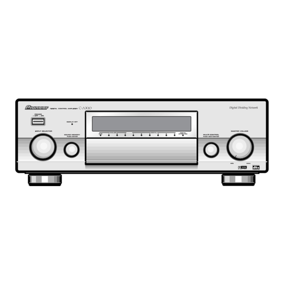
C-AX10 8. PANEL FACILITIES AND SPECIFICATIONS 8.1 PANEL FACILITIES DOLBY D I G I T A L 9 MASTER VOLUME knob This knob is used to adjust the volume. Turning this 1 Power switch (POWER —OFF/_ON) knob adjusts the volume for all channels simulta- Press the power switch to turn the amplifier on and off. - Page 114 C-AX10 When the front flip-down door is opened 0 - = ~ !@ # $ DOLBY D I G I T A L % ^ & * ( ) _ + ¡ ™ _ Balance Control button (BALANCE) % CHARACTER INPUT button...
- Page 115 This button is used to select whether the amplifier can receive operations from the remote control (ON) or not (OFF). Set to OFF when more than one Pioneer ampli- This figure shows the remote control when the fier is operating at the same time. When set to OFF, the slide cover has been pulled down.
- Page 116 C-AX10 ! All Tone Control button (ALL) This button is used to perform total tone control at the same settings for the front, centre, and surround chan- nels. @ Front Tone Control button (FRONT) This button is used to perform tone control for the front channels.
- Page 117 C-AX10 Display 2 3 4 5 6 8 9 0 ANALOG INPUT 1 OVER indicator 0 UNLOCK indicator This indicator turns on when the input level of the ana- This indicator turns on when the digital input signal is logue signal is too high or when the signal level during cut off.
-
Page 118: Rear Panel
5 Control input/output jacks (CONTROL IN, OUT) These jacks are used for controlling multiple Pioneer = DVD multichannel input jacks (DVD MULTI CH IN) devices having the Î mark from the remote control These jacks are used to connect to a DVD-Audio sensor of a single device. -
Page 119: Specifications
Analogue input LINE ........115 dB min. (acoustic correction) ÷ The signal format during PDIF mode is Pioneer’s own custom PHONO(MM) .... 84 dB min. (IHF A network, short circuit) format, and it does not conform to the IEC60958 standards. - Page 120 C-AX10 7Power supply/miscellaneous Supply voltage ... AC 230 V, 50/60Hz (For European model) ......... AC 120V, 60Hz (For American model) Power consumption ............. 52 W Dimensions ......440 (W) 150 (H) 410 (D) mm ..........17 (D) in. Weight ........22.2 kg48.9 lbs(without package)