Sony RMT-V405 Service Manual
Video cassette recorder
Hide thumbs
Also See for RMT-V405:
- Service manual (96 pages) ,
- Service manual (74 pages) ,
- Service manual (76 pages)
Table of Contents
Advertisement
SLV-SE240B/SE240D/SE240G/SE240I/SE440K/
QQ
3 7 63 1515 0
SERVICE MANUAL
TE
L 13942296513
System
Channel coverage
SE240B/SE640B:
SECAM (L)
VHF F2 to F10
UHF F21 to F69
CATV B to Q
HYPER S21 to S41
PAL (B/G)
VHF E2 to E12
VHF italian channels A to H
UHF E21 to E69
CATV S01 to S05, S1 to S20
HYPER S21 to S41
SE240D/SE640D/SE640E:
PAL (B/G)
VHF E2 to E12
VHF italian channels A to H
UHF E21 to E69
CATV S01 to S05, S1 to S20
HYPER S21 to S41
SE240G:
PAL (I)
UHF B21 to B69
www
.
http://www.xiaoyu163.com
SE640B/SE640D/SE640E/SE640N
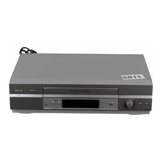
Photo: SLV-SE640D
SE240I:
PAL (I)
VHF IA to IJ, SA10 to SA13
UHF B21 to B69
CATV S01 to S05, S1 to S20
HYPER S21 to S41
SE440K/SE640N:
PAL (B/G, D/K)
VHF E2 to E12, R1 to R12
UHF E21 to E69, R21 to R69
CATV S1 to S41, S01 to S05
RF output signal
SE240D/SE240G/SE240I/SE440K/SE640D/
SE640E/SE640N/:
UHF channels 21 to 69
Aerial out
75-ohm asymmetrical aerial socket
Tape speed
SE240B:
SP: PAL
NTSC 33.35 mm/s (playback only)
SECAM
MESECAM
x
ao
u163
y
i
http://www.xiaoyu163.com
2 9
8
RMT-V405/V405A/V406/V406A
RMT-V406
Refer to the SERVICE MANUAL of VHS MECHANI-
CAL ADJUSTMENT MANUAL VII for MECHANICAL
ADJUSTMENTS. (9-921-790-11)
Q Q
3
6 7
1 3
1 5
SPECIFICATIONS
23.39 mm/s (recording/playback)
23.39 mm/s (recording/playback)
23.39 mm/s (playback only)
VIDEO CASSETTE RECORDER
co
.
9 4
2 8
AEP Model
SLV-SE240B/SE240D/SE240I/SE440K/
SE640B/SE640D/SE640E/SE640N
UK Model
TS-10 MECHANISM
0 5
8
2 9
9 4
2 8
LP: NTSC 16.67 mm/s (playback only)
SECAM
11.70 mm/s (recording/playback)
MESECAM
11.70 mm/s (playback only)
SE240D:
SP: PAL
23.39 mm/s (recording/playback)
NTSC 33.35 mm/s (playback only)
LP: NTSC 16.67 mm/s (playback only)
SE240G/SE240I/SE640D/SE640E:
SP: PAL
23.39 mm/s (recording/playback)
NTSC 33.35 mm/s (playback only)
LP: PAL
11.70 mm/s (recording/playback)
NTSC 16.67 mm/s (playback only)
EP: NTSC 11.12 mm/s (playback only)
SE440K/SE640N:
SP: PAL/MESECAM
23.39 mm/s (recording/playback)
NTSC 33.35 mm/s (playback only)
LP: PAL/MESECAM
11.70 mm/s (recording/playback)
NTSC 16.67 mm/s (playback only)
EP: NTSC 11.12 mm/s (playback only)
— Continued on next page —
m
9 9
SLV-SE240G
9 9
Advertisement
Table of Contents

Related Manuals for Sony RMT-V405


Summary of Contents for Sony RMT-V405
- Page 1 SLV-SE240B/SE240D/SE240G/SE240I/SE440K/ SE640B/SE640D/SE640E/SE640N 3 7 63 1515 0 RMT-V405/V405A/V406/V406A SERVICE MANUAL AEP Model SLV-SE240B/SE240D/SE240I/SE440K/ SE640B/SE640D/SE640E/SE640N UK Model SLV-SE240G Photo: SLV-SE640D TS-10 MECHANISM RMT-V406 Refer to the SERVICE MANUAL of VHS MECHANI- CAL ADJUSTMENT MANUAL VII for MECHANICAL ADJUSTMENTS. (9-921-790-11) L 13942296513...
- Page 2 LINE WITH MARK 0 ON THE SCHEMATIC DIAGRAMS AND IN THE PARTS LIST ARE CRITICAL TO SAFE OPERATION. REPLACE THESE COMPONENTS WITH SONY PARTS WHOSE PART NUMBERS APPEAR AS SHOWN IN THIS MANUAL OR IN SUPPLEMENTS PUBLISHED BY SONY. — 2 —...
-
Page 3: Table Of Contents
http://www.xiaoyu163.com TABLE OF CONTENTS 3 7 63 1515 0 Important Service Guide 2-3-10 Gear Loading Drive, Slider Cam, Lever Load S, T Ass’y Assembly ···································· 2-11 Mode Switch (Program Switch) Assembly Point ························· 4 2-3-11 Lever Pinch Drive, Lever Tension Drive Removal ·········· 2-12 How to eject the cassette tape 2-3-12 Lever Tension Ass’y, Band Brake Ass’y Removal ··········... -
Page 4: Important Service Guide
http://www.xiaoyu163.com 3 7 63 1515 0 IMPORTANT SERVICE GUIDE MODE SWITCH (PROGRAM SWITCH) ASSEMBLY POINT 1) When installing the ass’y deck on the Main PCB, be sure to align the assembly point of mode switch. ASSEMBLY POINT (ALIGN TWO ARROWS) Fig. -
Page 5: General
Never use the plug The VIDEO Plus+ system is manufactured under without the fuse cover. If you should lose the fuse license from Gemstar Development Corporation. cover, please contact your nearest Sony service station. Precautions Safety... -
Page 6: Step 1 : Unpacking
http://www.xiaoyu163.com 3 7 63 1515 0 A Z (eject) button (34) Rear panel Remote commander (wide) button (for TV) (14) (15) For SLV-SE640 DISPLAY button (14) (35) (38) D COUNTER/REMAIN button (38) E Programme number buttons* (13) (39) F - (ten’s digit) button (13) (39) H 2 (volume) +/–... -
Page 7: Step 2 : Setting Up The Remote Commander
TV. Call up the on-screen display DISPLAY To switch to wide mode, see the footnotes below this table for the applicable code numbers. Switch to/from wide mode of a Sony wide TV (For (wide) other manufactures’ wide TVs. Notes Manufacturer... -
Page 8: Step 3 : Connecting The Vcr
http://www.xiaoyu163.com 3 7 63 1515 0 If your TV has a Scart (EURO-AV) connector Step 3 : Connecting the VCR If your TV has a Scart (EURO-AV) connector, see page 17. If your TV does not have a Scart (EURO-AV) connector LINE-1 (EURO AV) Mains lead AERIAL IN... -
Page 9: Step 4 : Setting Up The Vcr With The Auto
http://www.xiaoyu163.com 3 7 63 1515 0 Notes Step 4 : Setting up the VCR with the Auto • Whenever you operate the Auto Set Up function, some of the settings (VIDEO Plus+, timer, etc.) will be reset. If this happens, you have to set them Set Up function again. -
Page 10: Presetting Channels
http://www.xiaoyu163.com 3 7 63 1515 0 Press </, repeatedly until the Presetting channels channel you want is displayed. MANUAL TUNING If some channels could not be preset using the Auto Set Up function, you can preset – NAME – – – – them manually. - Page 11 http://www.xiaoyu163.com 3 7 63 1515 0 Press OK, then press M/m to move Press M/m to highlight MANUAL SET UP, then press ,. to the desired programme position. TV STATION TABLE TV STATION TABLE NAME NAME – – – – –...
-
Page 12: Setting The Clock
http://www.xiaoyu163.com 3 7 63 1515 0 Set the day, month, and year in Setting the clock sequence by pressing , to select the item to be set, and press M/m to select the digits, then press ,. You must set the time and date on the VCR to use the timer features properly. The Auto Clock Set function works only if a station in your area is broadcasting a The day of the week is set AUTO CLOCK... -
Page 13: Recording Tv Programmes
http://www.xiaoyu163.com 3 7 63 1515 0 Starting playback automatically with one button (One Recording TV programmes Touch Play) (not available on SLV-SE240G/I) If you use the SMARTLINK connection, you can turn on the TV, set the TV to the video channel, and start playback automatically with one button. Before you start... -
Page 14: Recording Tv Programmes Using The Video Plus
http://www.xiaoyu163.com 3 7 63 1515 0 Recording what you are watching on the TV (TV Direct Recording TV programmes using the Rec) (not available on SLV-SE240G/I) If you use the SMARTLINK connection, you can easily record what you are ® VIDEO Plus+ system (not available on... -
Page 15: Setting The Timer Manually
http://www.xiaoyu163.com 3 7 63 1515 0 To use the VCR after setting the timer Setting the timer manually To use the VCR before a recording begins, just press ?/1. The indicator turns off and the VCR switches on. Remember to press ?/1 to reset the VCR to recording standby after using the VCR. -
Page 16: Additional Operations
http://www.xiaoyu163.com 3 7 63 1515 0 Additional Operations Playing/searching at various speeds • Adjust the picture using the PROGRAM +/– buttons on the VCR if: – Streaks appear while playing in slow motion. – Bands appear at the top or bottom while pausing. …... -
Page 17: Checking/Changing/Cancelling Timer Settings
http://www.xiaoyu163.com 3 7 63 1515 0 Recording programmes using Checking/changing/cancelling timer SYNCHRO REC button/indicator the Synchronized Recording function settings Before you start... … Before you start • Insert a tape with its safety tab in place. Make sure the tape is longer than the total •... -
Page 18: Searching Using The Index Function
http://www.xiaoyu163.com 3 7 63 1515 0 Selecting the sound during Hi-fi playback Searching using the index function Press AUDIO MONITOR to select the sound you want. (not available on SLV-SE240G/I) To listen to On-screen display Display window Stereo STEREO STEREO The VCR automatically marks the tape with an index signal at the point where each Left channel STEREO... -
Page 19: Reducing The Vcr's Power Consumption
http://www.xiaoyu163.com 3 7 63 1515 0 Changing menu options Reducing the VCR’s power consumption Press MENU, then select USER SET or EASY OPERATION and press You can turn off the indicators in the display window when the VCR is off (standby mode) to reduce the VCR’s power consumption. -
Page 20: Basic Editing
Troubleshooting). Clean the video heads using a Sony • Check that the digital tuner is turned on. video head cleaning cassette. If a Sony cleaning cassette is • Check that the satellite tuner is turned on. not available in your area, have the heads cleaned at your •... -
Page 21: Quick Start Guide
“To change programme 38 the RF channel.” RF channel 20 u163 ... Connect the mains lead to the mains. Index scan 62 ... Press OK. Index search 62 Sony Corporation Printed in Indonesia AC68-02101R Index 1-17E http://www.xiaoyu163.com... -
Page 22: Disassembly And Reassembly
http://www.xiaoyu163.com SLV-SE240B/SE240D/SE240G/SE240I/SE440K/ SE640B/SE640D/SE640E/SE640N 3 7 63 1515 0 2. DISASSEMBLY AND REASSEMBLY 2-1 CABINET AND PCB 2-1-1 Cabinet Top CABINET TOP 1 REMOVE 2 SCREWS 2 Lift up the Cabinet Top in the direction of arrow by releasing the Hook. L 13942296513 Fig. -
Page 23: Ass'y Panel Front
http://www.xiaoyu163.com 3 7 63 1515 0 2-1-3 Ass’y-Panel Front 2 RELEASE 3 HOOKS 1 RELEASE 4 HOOKS ASS'Y-PANEL FRONT (BOTTOM VIEW) (TOP VIEW) Fig. 2-3 Ass’y-Panel Front 2-1-4 Ass’y Jack PCB Disconnect the CN701 from the Ass'y PCB-Main and then lift the Ass'y PCB-Jack up. L 13942296513 CN702 CN704... -
Page 24: Ass'y Main-Pcb, Deck
http://www.xiaoyu163.com 3 7 63 1515 0 2-1-5 Ass’y MAIN-PCB, DECK 3 4 SCREWS 4 FLAT CABLE 5 FLAT CABLE 8 ASS'Y-DECK 6 FLAT CABLE L 13942296513 1 2 SCREWS 9 ASS'Y MAIN-PCB 7 RELEASE 1 TAB 2 BRACKET-FRAME u163 Fig. 2-5 Ass’y Main-PCB, Deck http://www.xiaoyu163.com... -
Page 25: Vcr Deck Parts Locations
http://www.xiaoyu163.com 3 7 63 1515 0 2-2 VCR DECK PARTS LOCATIONS 2-2-1 Top View L 13942296513 Fig. 2-6 Top parts Location-1 1 GEAR FL CAM 2 MOTOR LOADING ASS’Y 3 LEVER FL ARM ASS’Y 4 HOLDER FL CASSETTE ASS’Y 5 LEVER FL DOOR 6 SLIDER FL DRIVE u163 http://www.xiaoyu163.com... - Page 26 http://www.xiaoyu163.com 3 7 63 1515 0 L 13942296513 qa q; qs Fig. 2-7 Top Parts Location-2 1 FE HEAD 8 DISK S REEL 2 CYLINDER ASS’Y 9 LEVER S BRAKE ASS’Y 3 ACE HEAD ASS’Y q; GEAR IDLE 4 LEVER UNIT PINCH ASS’Y qa LEVER IDLE 5 LEVER #9 GUIDE ASS’Y qs LEVER T BRAKE ASS’Y...
-
Page 27: Bottom View
http://www.xiaoyu163.com 3 7 63 1515 0 2-2-2 Bottom View 1 2 3 L 13942296513 9 q; Fig. 2-8 Bottom Parts Location 1 GEAR JOINT 1 2 GEAR JOINT 2 3 BRAKET GEAR 4 MOTOR CAPSTAN ASS’Y 5 LEVER T LOAD ASS’Y 6 GEAR LOADING DRIVE 7 LEVER S LOAD ASS’Y 8 HOLDER CLUTCH ASS’Y... -
Page 28: Vcr Deck
http://www.xiaoyu163.com 3 7 63 1515 0 2-3 VCR DECK 2-3-1 Holder FL Cassette Ass’y Removal 2-3-2 Lever FL Door Removal 1) Pull the Holder FL Cassette Ass’y 1 to the eject position. 1) Release the Hook 2 and Remove the Lever FL Door 1 in the 2) Pull the Holder FL Cassette Ass’y 1 as grasping the Holder FL direction of arrow “A”. -
Page 29: Slider Fl Drive, Gear Fl Cam Removal
http://www.xiaoyu163.com 3 7 63 1515 0 2-3-3 Slider FL Drive, Gear FL Cam Removal 2-3-4 Lever FL Arm Ass’y Removal 1) Pull the Slider FL Drive 1 to the front direction. 1) Push the hole “A” in the direction of arrow “B” use the pin.(about 2) Remove the Slider FL Drive 1 in the direction of arrow. -
Page 30: Gear Worm Wheel Removal
http://www.xiaoyu163.com 3 7 63 1515 0 2-3-5 Gear Worm Wheel Removal 2-3-6 Cable Flat Removal 1) Remove the Gear Worm wheel 1. 1) Remove the Drum connecting part of Cable Flat 1 from Connector Waffer 2. 2) Remove the Loading Motor connecting part of Cable Flat 1 from Connector Waffer 3. -
Page 31: Motor Loading Ass'y Removal
http://www.xiaoyu163.com 3 7 63 1515 0 2-3-7 Motor Loading Ass’y Removal 2-3-8 Bracket Gear, Gear Joint 2, 1 Removal 1) Remove the screw 1. 1) Remove the SCREW 1. 2) Remove the Motor Loading Ass’y 2. 2) Remove the Bracket Gear 2. 3) Remove the Gear Joint 2 3. -
Page 32: Gear Loading Drive, Slider Cam
http://www.xiaoyu163.com 3 7 63 1515 0 2-3-9 Gear Loading Drive, Slider Cam, 2-3-10 Gear Loading Drive, Slider Cam, Lever Load S, T Ass’y Removal Lever Load S, T Ass’y Assembly 1) Remove the Belt Pulley. (Refer to Fig. 2-36) 1) When reinstalling, be sure to align dot of Lever Load T Ass’y 1 2) Remove the Gear Loading Drive 1 after releasing Hook [A] in with dot of Lever Load S Ass’y 2 as shown in drawing, (Refer to the direction arrow as shown in detail drawing. -
Page 33: Lever Pinch Drive, Lever Tension Drive Removal
http://www.xiaoyu163.com 3 7 63 1515 0 2-3-11 Lever Pinch Drive, 2-3-12 Lever Tension Ass’y, Lever Tension Drive Removal Band Brake Ass’y Removal 1) Remove the Lever Pinch Drive 1, Lever Tension Drive 2. 1) Remove the Lever Brake S Ass’y (Refer to Fig 2-23). 2) Remove the Spring Tension Lever 1. -
Page 34: Lever Brake S, T Ass'y Removal
http://www.xiaoyu163.com 3 7 63 1515 0 2-3-13 Lever Brake S, T Ass’y Removal 2-3-14 Gear Idle Ass’y Removal 1) Push the Lever Idle 1 in the direction of arrow “A”, “B”. 1) Release the Hook [A] and the Hook [B], [C] in the direction of arrow as shown in Fig 2-23. -
Page 35: Disk S, T Reel Removal
http://www.xiaoyu163.com 3 7 63 1515 0 2-3-15 Disk S, T Reel Removal 2-3-16 Holder Clutch Ass’y Removal 1) Lift the Disk S, T Reel 1, 2. 1) Remove the Washer Slit 1. 2) Lift the Holder Clutch Ass’y 2. Note: When you reinstall Holder Clutch Ass’y 1) Check the condition of spring as shown in detail A. -
Page 36: Lever Up Down Ass'y, Gear Center Ass'y Removal
http://www.xiaoyu163.com 3 7 63 1515 0 2-3-17 Lever Up Down Ass’y, Gear Center 2-3-18 Guide Cassette Door Removal Ass’y Removal 1) Lift the Hook [A]. 2) Rotate the Guide Cassette Door 1 in the direction of arrow. 1) Remove the 2 hooks in the direction of arrow as shown Fig. 2-26 and lift the Lever Up Down Ass’y 1. -
Page 37: Lever Unit Pinch Ass'y, Plate Joint
http://www.xiaoyu163.com 3 7 63 1515 0 2-3-19 Lever Unit Pinch Ass’y, Plate Joint, 2-3-20 Lever #9 Guide Ass’y Removal Spring Pinch Drive Removal 1) Remove the Spring #9 Guide 1. 2) Lift the Spring #9 Guide Ass’y 2 in the direction of arrow “A”. 1) Lift the Unit Pinch Ass’y 1. -
Page 38: Fe Head Removal
http://www.xiaoyu163.com 3 7 63 1515 0 2-3-22 ACE Head Removal 2-3-21 FE Head Removal 1) Pull out the FPC from connector of ACE Head Ass’y 2. 1) Remove the screw 1. 2) Remove the screw 1. 2) Lift the FE Head 2. 3) Lift the ACE Head Ass’y 2. -
Page 39: Slider S, T Ass'y Removal
http://www.xiaoyu163.com 3 7 63 1515 0 2-3-23 Slider S, T Ass’y Removal 2-3-24 Plate Ground Deck, Cylinder Ass’y Removal 1) Move the Slider S, T Ass’y 1, 2 to slot, and then lift it to remove. 1) Remove the 3 Screws 1. (Refer to arrow) 2) Lift the Plate Ground Deck 2. -
Page 40: Belt Pulley Removal
http://www.xiaoyu163.com 3 7 63 1515 0 2-3-25 Belt Pulley Removal 2-3-26 Motor Capstan Ass’y Removal 1) Remove the Belt Pulley 1. 1) Remove the Damper Capstan 1 in the direction of arrow. 2) Remove the 3 Screws 2. Note: Take extreme care not to get grease on Belt Pulley 1 at 3) Remove the Motor Capstan Ass’y 3. -
Page 41: Post #8 Guide Ass'y Removal
http://www.xiaoyu163.com 3 7 63 1515 0 2-3-27 Post #8 Guide Ass’y Removal 2-3-29 How to Eject the Cassette Tape (If the unit does not operate on condition that is 1) Rotate the Post #8 Guide Ass’y 1 in the direction of arrow to lift inserted into housing Ass’y) 1) Turn the Gear worm 1 clockwise with screw driver.(Refer to arrow) -
Page 42: The Table Of Cleaning, Lubrication And Replacement Time About Principal Parts
http://www.xiaoyu163.com 3 7 63 1515 0 2-4 THE TABLE OF CLEANING, LUBRICATION AND REPLACEMENT TIME ABOUT PRINCIPAL PARTS 1) The replacement time of parts is not life of parts. 2) The table 2-1 is that the VCR Set is in normal condition (normal temperature, normal humidity). The checking period may be changed owing to the condition of use, runtime and environmental conditions. -
Page 43: P.c.boards
http://www.xiaoyu163.com SLV-SE240B/SE240D/SE240G/SE240I/SE440K/ SE640B/SE640D/SE640E/SE640N 3 7 6 3 1 5 1 5 0 3. P.C.BOARDS 3-1 Main PCB - - - - - - - - - - - - - - - - - - - - - - - - - - - - - - - - - - - - - - - - - - - - - - 3-3 3-2 Dial Timer PCB (Hi-Fi model) - - - - - - - - - - - - - - - - - - - - - - - - - - - - - - - - - 3-7 3-3 Front A/V PCB (Hi-Fi model) - - - - - - - - - - - - - - - - - - - - - - - - - - - - - - - - - - 3-9 •... -
Page 44: Main Pcb
http://www.xiaoyu163.com 3 7 6 3 1 5 1 5 0 3-1 MAIN PCB COMPONENT SIDE 1 3 9 4 2 2 9 6 5 1 3 w w w u 1 6 3 http://www.xiaoyu163.com... - Page 45 http://www.xiaoyu163.com 3 7 6 3 1 5 1 5 0 CONDUCTOR SIDE 1 3 9 4 2 2 9 6 5 1 3 w w w u 1 6 3 http://www.xiaoyu163.com...
-
Page 46: Dial Timer Pcb (Hi-Fi Model)
http://www.xiaoyu163.com 3 7 6 3 1 5 1 5 0 3-2 DIAL TIMER PCB (Hi-Fi model) COMPONENT SIDE 1 3 9 4 2 2 9 6 5 1 3 CONDUCTOR SIDE w w w u 1 6 3 http://www.xiaoyu163.com... -
Page 47: Front A/V Pcb (Hi-Fi Model)
http://www.xiaoyu163.com 3 7 6 3 1 5 1 5 0 3-3 FRONT A/V PCB (Hi-Fi model) COMPONENT SIDE CONDUCTOR SIDE 1 3 9 4 2 2 9 6 5 1 3 w w w u 1 6 3 3-10 http://www.xiaoyu163.com... - Page 48 http://www.xiaoyu163.com SLV-SE240B/SE240D/SE240G/SE240I/SE440K/ SE640B/SE640D/SE640E/SE640N 3 7 6 3 1 5 1 5 0 4. SCHEMATIC DIAGRAMS Block Identification of Main PCB - - - - - - - - - - - - - - - - - - - - - - - - - - - - - - - - 4-3 4-1 S.M.P.S.
-
Page 49: Block Identification Of Main Pcb
http://www.xiaoyu163.com 3 7 6 3 1 5 1 5 0 BLOCK IDENTIFICATION OF MAIN PCB 1 3 9 4 2 2 9 6 5 1 3 Component Side Conductor Side w w w u 1 6 3 http://www.xiaoyu163.com... - Page 50 http://www.xiaoyu163.com 3 7 6 3 1 5 1 5 0 4-1 S.M.P.S. 1 3 9 4 2 2 9 6 5 1 3 w w w u 1 6 3 http://www.xiaoyu163.com...
-
Page 51: Power
http://www.xiaoyu163.com 3 7 6 3 1 5 1 5 0 4-2 POWER 1 3 9 4 2 2 9 6 5 1 3 w w w u 1 6 3 http://www.xiaoyu163.com... -
Page 52: System Control/Servo
http://www.xiaoyu163.com 3 7 6 3 1 5 1 5 0 4-3 SYSTEM CONTROL/SERVO 1 3 9 4 2 2 9 6 5 1 3 w w w u 1 6 3 4-10 http://www.xiaoyu163.com... -
Page 53: Audio/Video
http://www.xiaoyu163.com 3 7 6 3 1 5 1 5 0 4-4 AUDIO/VIDEO 1 3 9 4 2 2 9 6 5 1 3 w w w u 1 6 3 4-11 4-12 http://www.xiaoyu163.com... -
Page 54: Hi-Fi (Hi-Fi Model)
http://www.xiaoyu163.com 3 7 6 3 1 5 1 5 0 4-5 Hi-Fi (Hi-Fi model) 1 3 9 4 2 2 9 6 5 1 3 w w w u 1 6 3 4-13 4-14 http://www.xiaoyu163.com... -
Page 55: Tm-Block
http://www.xiaoyu163.com 3 7 6 3 1 5 1 5 0 4-6 TM-BLOCK 1 3 9 4 2 2 9 6 5 1 3 w w w u 1 6 3 4-15 4-16 http://www.xiaoyu163.com... -
Page 56: Osd/Vps/Pdc
http://www.xiaoyu163.com 3 7 6 3 1 5 1 5 0 4-7 OSD/VPS/PDC 1 3 9 4 2 2 9 6 5 1 3 w w w u 1 6 3 4-17 4-18 http://www.xiaoyu163.com... -
Page 57: Secam (Se240B/Se640B)
http://www.xiaoyu163.com 3 7 6 3 1 5 1 5 0 4-8 SECAM (SE240B/SE640B) 1 3 9 4 2 2 9 6 5 1 3 w w w u 1 6 3 4-19 4-20 http://www.xiaoyu163.com... -
Page 58: A2/Nicam (Hi-Fi Model)
http://www.xiaoyu163.com 3 7 6 3 1 5 1 5 0 4-9 A2/NICAM (Hi-Fi model) 1 3 9 4 2 2 9 6 5 1 3 w w w u 1 6 3 4-21 4-22 http://www.xiaoyu163.com... -
Page 59: Input-Output (2 Scart Jack)
http://www.xiaoyu163.com 3 7 6 3 1 5 1 5 0 4-10 INPUT-OUTPUT (2 SCART JACK) 1 3 9 4 2 2 9 6 5 1 3 w w w u 1 6 3 4-23 4-24 http://www.xiaoyu163.com... -
Page 60: Function (Hi-Fi Model)
http://www.xiaoyu163.com 3 7 6 3 1 5 1 5 0 4-11 FUNCTION (Hi-Fi model) 1 3 9 4 2 2 9 6 5 1 3 w w w u 1 6 3 4-25 4-26E http://www.xiaoyu163.com... -
Page 61: Alignment And Adjustments
http://www.xiaoyu163.com SLV-SE240B/SE240D/SE240G/SE240I/SE440K/ SE640B/SE640D/SE640E/SE640N 3 7 63 1515 0 5. ALIGNMENT AND ADJUSTMENTS 5-1 VCR ADJUSTMENT 1) X-Point (Tracking center) adjustment, “Head switching adjustment” and “NVRAM option setting” can be adjusted with remote control. 2) When replacing the Micom (IC601) and NVRAM (IC605 ; EEPROM) be sure to adjust the “Head switching adjustment” and “NVRAM option setting”. -
Page 62: Test Point Location For Adjustment Mode Setting
http://www.xiaoyu163.com 3 7 63 1515 0 5-1-2 Test point location for adjustment mode setting L 13942296513 PRESS Fig. 5-2 Main PCB (Top View) u163 http://www.xiaoyu163.com... -
Page 63: Head Switching Point Adjustment
http://www.xiaoyu163.com 3 7 63 1515 0 5-2 HEAD SWITCHING POINT ADJUSTMENT 1) Playback the alignment tape. 2) Press the “SW702” button on Main PCB to set the adjustment mode. (See Fig. 5-2) 3) Press the “SP/LP” button of remote control then adjustment is operated automatically. (See Fig. 5-1) 4) Turn the Power off. - Page 64 http://www.xiaoyu163.com 3 7 63 1515 0 <Table 5-1> MODELS OPTION NUMBER SLV-SE240D 4, 5, 11, 13, 14, 16, 18, 30, 34, 35, 38, 40, 42, 45, 47, 49, 60, 61, 63, 69, 72 SLV-SE240I 4, 5, 10, 11, 13, 14, 18, 25, 26, 30, 33, 34, 35, 38, 40, 43, 45, 47, 49, 60, 61, 63, 69, 72 SLV-SE240G 4, 5, 10, 11, 13, 14, 18, 27, 30, 33, 34, 35, 38, 40, 41, 45, 47, 49, 60, 61, 63, 69, 72 SLV-SE240B...
-
Page 65: Vcr Mechanical Adjustment
http://www.xiaoyu163.com 3 7 63 1515 0 5-4 VCR MECHANICAL ADJUSTMENT 5-4-1 Tape Transport System and Adjustment Locations The tape transport system has been adjusted precisely in the factory. Alignment is not necessary except for the following : 1) Noise observed on the screen. 2) Tape damage. -
Page 66: Tape Transport System Adjustment
http://www.xiaoyu163.com 3 7 63 1515 0 5-4-2 Tape Transport System Adjustment When parts are replaced, perform the required adjustments by referring to procedures for the tape transport system. If there are any changes to the tape path, first run a T-120 tape and make sure excessive tape wrinkle does not occur at the tape guides. If tape wrinkle is observed at the guide roller S, T, turn the guide roller S, T until wrinkle disappears. - Page 67 http://www.xiaoyu163.com 3 7 63 1515 0 b. ACE HEAD TILT ADJUSTMENT 1) Playback a blank tape and observe the position of the tape at the lower flange of tape guide. 2) Confirm that there is no curl or wrinkle at the lower flange of tape guide as shown in Fig. 5-9 (B). 3) If a curl or wrinkle of the tape occurs, slightly turn the screw (A) tilt adjust on the ACE head ass’y.
- Page 68 http://www.xiaoyu163.com 3 7 63 1515 0 d. ACE HEAD POSITION (X-POINT) ADJUSTMENT 1) Playback the alignment tape (Color bar) 2) Press the “SW702” button on Main PCB to set the adjustment mode. (See Fig. 5-2) 3) Press the “0, 5” remote control buttons, then adjustment is operates automatically. (See Fig. 5-1) 4) Connect the CH-1 probe to “Envelope”...
- Page 69 http://www.xiaoyu163.com 3 7 63 1515 0 (2) Linearity adjustment (Guide roller S, T adjustment) 1) Playback the Mono Scope alignment tape (SP mode). 2) Observe the video envelope signal on an oscilloscope (triggered by the video switching pulse). 3) Make sure the video envelope waveform (at its minimum) meets the specification shown in Fig. 5-11. If it does not, adjust as follows : Note: a=Maximum output of the video RF envelope.
- Page 70 http://www.xiaoyu163.com 3 7 63 1515 0 6) Play back the Mono Scope alignment tape (SP mode). 7) Connect an oscilloscope CH-1 to the “Envelope” and CH-2 to the “H’D SW Pulse” for triggering. 8) Turn the guide roller heads with a flat head ( ) driver to obtain a flat video RF envelope as shown in Fig.
-
Page 71: Reel Torque
http://www.xiaoyu163.com 3 7 63 1515 0 (4) Envelope Check 1) Make recordings on T-120 (E-120) and T-160 (E-180) tape. Make sure the playback output envelope meets the specification as shown in Fig. 5-15. 2) Play back a self recorded tape (recording made on the unit using with T-120 (E-120). The video envelope should meet the specification as shown in Fig. -
Page 72: Repair Parts List
http://www.xiaoyu163.com SLV-SE240B/SE240D/SE240G/SE240I/SE440K/ SE640B/SE640D/SE640E/SE640N 3 7 63 1515 0 6. REPAIR PARTS LIST Page 6-1 Exploded Views - - - - - - - - - - - - - - - - - - - - - - - - - - - - - - - - - - - - - - - - - 6-1-1 Instrument Assembly (Mono model) - - - - - - - - - - - - - - - - - - - - - - - - - - - - - - - - - - 6-1-2 Instrument Assembly (Hi-Fi model) - - - - - - - - - - - - - - - - - - - - - - - - - - - - - - - - - - - 6-1-3 Mechanical Parts (Top Side) - - - - - - - - - - - - - - - - - - - - - - - - - - - - - - - - - - - - - - - -... -
Page 73: Exploded Views
0 200 9-885-056-35 ASSY PANEL FRONT 240D (SE240D) 1-823-025-11 POWER CORD Y352 (SE240G/SE240I) 3-075-088-01 COVER (S) REMOTE CONTROL BATTERY CN3A1S 1-824-062-11 CABLE FLAT 6P 1-477-269-11 COMMANDER, STANDARD (RMT-V405) u163 9-885-056-49 DOOR, CASSETTE (EURO_S360) (SE240D/SE240G/SE240I/SE440K) 9-885-056-98 ASSY DECK 9-885-056-47 PAL (S360), UPPER CASE... -
Page 74: Instrument Assembly (Hi-Fi Model)
http://www.xiaoyu163.com 3 7 63 1515 0 6-1-2 Instrument Assembly (Hi-Fi model) Except for Assy Cylinder, H/Cleaner Lever Assy CN3A1S not supplied not supplied not supplied not supplied not supplied L 13942296513 not supplied not supplied The components identified by mark 0or dotted line with mark 0 are critical for safety. -
Page 75: Mechanical Parts (Top Side)
http://www.xiaoyu163.com 3 7 63 1515 0 6-1-3 Mechanical Parts (Top Side) B561 G001 B475 K490 not supplied supplied G555 not supplied not supplied G510 G680 not supplied G420 G480 G450 K546 K250 G560 K240 K248 L 13942296513 G681 B410 K350 K110 B440 not supplied... -
Page 76: Mechanical Parts (Bottom Side)
http://www.xiaoyu163.com 3 7 63 1515 0 6-1-4 Mechanical Parts (Bottom Side) G542 B462 not supplied not supplied B560 not supplied not supplied not supplied not supplied not supplied not supplied not supplied not supplied L 13942296513 not supplied not supplied not supplied not supplied not supplied... -
Page 77: Electrical Parts List
http://www.xiaoyu163.com MAIN 3 7 63 1515 0 6-2 ELECTRICAL PARTS LIST NOTE: • Items marked “*” are not stocked since they are • Mono model: S E 2 4 0 B / S E 2 4 0 D / S E 2 4 0 G / •... - Page 78 http://www.xiaoyu163.com MAIN 3 7 63 1515 0 Ref. No. Part No. Description Remarks Ref. No. Part No. Description Remarks < IC > Q1P105 1-804-427-11 TRANSISTOR KSR1001 IC301 1-805-361-11 IC VIDEO Q1P106 1-804-421-11 TRANSISTOR KSC945 (Hi-Fi model) IC501 1-804-703-11 IC HIFI (Hi-Fi model) Q1P107 1-804-429-11 TRANSISTOR KSR2001 (Hi-Fi model) IC601 9-885-056-40 IC MICON (WE) (EXCEPT SE440K/SE640N)
- Page 79 9-885-056-95 ASSY CYLINDER 4HD (SE440K) G001 9-885-056-96 ASSY CYLINDER 6HD (Hi-Fi model) ACCESSORIES & PACKING MATERIALS ******************************** u163 1-477-269-11 COMMANDER, STANDARD (RMT-V405) (SE240D/SE240G/SE240I/SE440K) 1-477-270-11 COMMANDER, STANDARD (RMT-V405A) Note : (SE240B) The components identified by mark 0 or dotted line with mark 0 are critical for safety.
- Page 80 SLV-SE240B/SE240D/SE240G/SE240I/SE440K/ SE640B/SE640D/SE640E/SE640N 3 7 63 1515 0 L 13942296513 u163 Sony Corporation 2004A0500-1 Home Storage Company 9-929-792-11 ©2004.1 — 106 — Published by Quality Assurance Dept. http://www.xiaoyu163.com...