Sony PCS-TL50 Operating Instructions Manual
Video communication system
Hide thumbs
Also See for PCS-TL50:
- Operating instructions manual (243 pages) ,
- Operation manual (240 pages) ,
- Quick connection manual (2 pages)
Table of Contents
Advertisement
Quick Links
Download this manual
See also:
Operating Manual
Advertisement
Table of Contents

Related Manuals for Sony PCS-TL50


Summary of Contents for Sony PCS-TL50
- Page 1 3-869-200-17 (1) Video Communication System Operating Instructions (Version 2.3) Before operating the unit, please read this manual thoroughly and retain it for future reference. PCS-TL50 © 2004 Sony Corporation...
- Page 2 To reduce the risk in the space provided below. Refer to these of fire or electric shock, refer servicing to numbers whenever you call upon your Sony qualified service personnel. dealer regarding this product. This device complies with Part 15 of the Model No.
- Page 3 This manual focuses on using ISDN lines to conduct a videoconference, but it also covers non-ISDN lines. If you use ISDN lines, consult your Sony dealer for more information. • The ISDN service may not be available in some areas.
-
Page 4: Table Of Contents
Table of Contents Setting the Video Communication Chapter 1: Installation and System to Standby Mode ....29 Preparation Opening the Shutter ....30 Adjusting the Volume ....31 Using This Manual ......10 Adjusting the Picture Quality ..31 Features ..........11 Displaying the Help ....31 System Components ...... -
Page 5: Table Of Contents
Registering a Remote Party in the Address in the Launcher Menu .. 87 Phone Book ........64 Calling a Remote Party Registered in the Phone Book ...... 88 Registering a New Remote Party 64 Calling a Remote Party not Changing the Contents of the Phone Registered in the Phone Book Using Book ..........66 the Detailed Dial Menu .... - Page 6 Switching the Picture Displayed on Using a Convenient Menu Available the TV Monitor ......111 during Communication — Communication Submenu ..132 Monitoring the Local Picture as a Window Picture – PinP Feature ..112 Using External Microphone and Headphones ........133 Monitoring the Local and Remote Pictures Simultaneously –...
-
Page 7: Table Of Contents
Ending the Multipoint Videoconference Chapter 7: Multipoint ..........180 Videoconference Notes on Secondary Terminals ..182 Connection Examples for a Multipoint Connecting the External MCU ..183 Videoconference ......157 Activating the Chair Control ..183 Using the LAN Connection (Up to 6 Multipoint Attribute ....... - Page 8 PCS-TL50 Video Communication Select a Tool ........220 System ........260 How to Use “Controller” ....221 PCS-RTL50 Remote Commander To Control the PCS-TL50 from the ........262 On-screen Controller ....221 PCS-AC19V8 AC Adaptor ..262 To Control the PCS-TL50 from the...
-
Page 9: Table Of Contents
Signals ........264 Pin Assignment ......266 Pin Assignment on Optional Board Connectors ........267 List of Port Numbers Used on the PCS-TL50 ......... 268 Videoconferencing Room Layout .. 270 Camera Range ......270 Glossary ......... 272 Menu Configuration .......275 Table of Contents... -
Page 10: Chapter 1: Installation And Preparation
This chapter describes how to register and This chapter shows you how to control the set up all the necessary items for system PCS-TL50 or set it up via a Web browser. administrators, using the on-screen menus. Appendix Chapter 3: Daily Videoconference... -
Page 11: Features
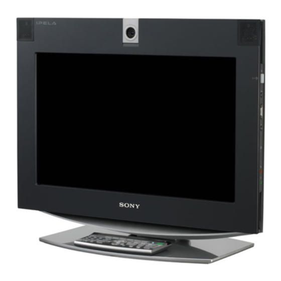
The Video Communication System accepts a LAN bandwidth of up to 1920 Kbps. It also The PCS-TL50 Video Communication allows connection to as many as three ISDN System is a videoconferencing system that lines; 6B channels usable by using the... - Page 12 ................“IPELA” and are trademarks of Sony Corporation. Features...
-
Page 13: System Components
The PCS-TL50 Video Communication System is composed of basic system components for a basic videoconference, and optional equipment for an enhanced videoconference. Basic System Components The PCS-TL50 Video Communication System is the basic system of the Videoconferencing System. It contains the following components: Unit Description... -
Page 14: Optional Equipment
Optional Equipment The following optional devices are used to enhance your videoconference. Unit Description ISDN Unit Used to connect to an ISDN line. Up to three ISDN PCSA-B384S lines; 6B channels usable. (The PCSA-B384S and PCS-B384 have the same functions. This manual uses the PCSA-B384S as a representative model.) PCS-B384 ISDN Unit... - Page 15 Unit Description PCSA-A3 Microphone Unidirectional microphone. It is recommended when you want to pick up the voice of a speaker directed toward the microphone. CTE-600 Communication Integrated microphone/speaker system suitable for Transducer remote communication. It is used by connecting to the Data Solution Box.
-
Page 16: System Configuration
System Configuration The PCS-TL50 Video Communication System has various system configuration capabilities using the basic components and optional equipment. This section describes seven typical examples. System Configuration via a LAN This allows you: • To hold a point-to-point videoconference over LAN. -
Page 17: System Configuration Via An Isdn
Up to three ISDN lines with the PCSA-B384S ISDN Unit or up to six ISDN lines with the PCSA-B768S ISDN Unit can be connected to one PCS-TL50 Each ISDN line is composed of two B channels that carry data signals on the... -
Page 18: System Configuration Via A Lan For Multipoint Conference
• To hold a multipoint videoconference among up to ten sites over LAN. • To show still images stored in a “Memory Stick”. System configuration 1 PCS-TL50 Video Communication System 2 PCS-RTL50 Remote Commander 3 PCS-323M1 H.323 MCU software (not supplied) -
Page 19: System Configuration Via An Isdn For Multipoint Conference
• To hold a multipoint videoconference among up to six sites over ISDN. • To show still images stored in a “Memory Stick”. System configuration 1 PCS-TL50 Video Communication System 2 PCS-RTL50 Remote Commander 3 PCS-320M1 H.320 MCU software (not supplied) -
Page 20: System Configuration Via A Lan And Isdn For Multipoint Conference
ISDN. • To show still images stored in a “Memory Stick”. System configuration * Be sure to make a connection 1 PCS-TL50 Video Communication System via LAN. 2 PCS-RTL50 Remote Commander 3 PCS-323M1 H.323 MCU software (not supplied) The illustration shows an 4 PCS-320M1 H.320 MCU software (not supplied) -
Page 21: System Configuration Via A Lan For Multipoint Data Conference
• To pick up a large number of participants’ voices using up to five external microphones connected to the Data Solution Box. System configuration 1 PCS-TL50 Video Communication System 2 PCS-RTL50 Remote Commander 3 PCS-323M1 H.323 MCU software (not supplied) -
Page 22: System Configuration Via An Isdn For Multipoint Data Conference
• To pick up a large number of participants’ voices using up to five external microphones connected to the Data Solution Box. System configuration 1 PCS-TL50 Video Communication System The illustration shows an example 2 PCS-RTL50 Remote Commander using the PCSA-B768S ISDN 3 PCS-320M1 H.320 MCU software (not supplied) -
Page 23: System Connections
System Connections This section describes the typical system connections. Using the Connectors The connectors are in the inside of the rear cover. When using the connectors, remove the rear cover, connect cables to the connectors, and replace the rear cover. To remove the rear cover Pull the rear cover toward you. -
Page 24: Notes On Connections
100BASE-TX/10BASE-T connector. System Connection via a LAN Connect in order. Power cord* to a wall outlet PCS-TL50 Video to DC19.5V Communication System PCS-AC19V8 AC adaptor* to 100BASE-TX/10BASE-T UTP cable (category 5, straight)**... -
Page 25: System Connection Via An Isdn
Video Communication System. Doing so may cause malfunction of the system. Connect in order. PCS-AC19V8 AC adaptor* Power cord* to DC19.5V PCS-TL50 Video to a wall outlet Communication System Interface cable to ISDN UNIT (supplied with the ISDN unit) TERMINAL ISDN Unit... -
Page 26: Preparing The System
Preparing the System Inserting Batteries into the Remote Commander Most of the operations with the Video Communication System can be controlled with the supplied Remote Commander. Remove the battery compartment cover. Insert two size AA (R6) batteries (supplied) with correct polarities into the battery compartment. -
Page 27: Placing The Remote Commander On The Stand
• Do not mix old and new batteries, or different types of batteries. • Do not attempt to charge the batteries. • If you do not intend to use the Remote Commander for a long period of time, remove the batteries. •... -
Page 28: Turning The System On/Off
Turning the System On/Off This section describes how to turn on or off the Video Communication System. Turning On Before turning on the system, make sure that the system connections have been completed correctly. For connecting the system, see “System Connections” on page 23. Turn on the power of any equipment to be used for the videoconference. -
Page 29: Turning Off
If connection of the Data Solution Box or ISDN Unit to the Video Communication System is not re-established even after the system power is recovered, consult a Sony dealer. Turning Off Press the (power) switch on the right side of the system for more than one second to turn the system off. -
Page 30: Opening The Shutter
Opening the Shutter The system is equipped with a shutter to hide the camera. Before starting a videoconference, open the shutter by sliding the shutter switch on the top of the system to the right. If the shutter is closed, the picture on the local site will not be seen on the remote site. -
Page 31: Adjusting The Volume
Adjusting the Volume Press the VOLUME +/– buttons on the Remote Commander to set the volume level appropriately. Volume Notes • The volume can be adjusted for the picture of a videoconference, the image from a computer and the image from video equipment. •... -
Page 32: Setting Up The System For The First Time - Initial Setup Wizard
When the ISDN Unit is not connected, Setting Up the the LAN Setup Wizard is displayed. Proceed to step 9. System for the First Set the following items on the ISDN Time — Initial Setup line. Wizard ISDN Setup Wizard When you turn on the Video Communication System for the first time Country/Region... - Page 33 When you select Auto SPID (only addresses in the B1 to F2 text boxes in for customers in the USA and addition to the A1 and A2 boxes. To open Canada) the menu with these text boxes, select “Next”, then press the ENTER button. You can automatically set up the Area Code and Local Number on this page, Use the V, v, B or b button to select...
- Page 34 IP Address: Enter your IP address. Network Mask: Enter your network mask. Gateway Address: Enter your default gateway address. DNS Address: Enter your DNS (Domain Name System) server address. Note When you set “DHCP Mode” to “Auto”, the assigned IP address is shown in the launcher menu (page 82) or Machine Information menu (page 60).
-
Page 35: Using The Menu
Using the Menu The Video Communication System uses the on-screen menus to make various adjustments and settings. This section gives a brief introduction of the menus. Menu Configurations The menus of this system configure as described below. For more detailed menu configurations, refer to “Menu Configuration” on page 275. -
Page 36: Introduction Of Menus
One Touch Dial Operation menu Menu Icons Selecting the icons on the menu tabs shown One Touch Dial Operation on the left side of the menu displays each menu. Dial Edit Delete Icon Displayed menu Returns to the previous menu. Cancel Phone Book menu The One Touch Dial Operation menu is used... - Page 37 Detailed Dial menu Still Image menu Still Image Detailed Dial Send Line I/F Continuous Send LAN Bandwidth Clear 1024 Kbps Save Dial Save The Still Image menu is used to control still The Detailed Dial menu is used to call a images.
- Page 38 Memory Stick menu Memory Stick The Memory Stick menu is used when you are using a “Memory Stick”. The menu is not displayed unless a “Memory Stick” is installed in the Video Communication System. The menu appears when you press the MENU button on the Remote Commander to display the Setup menu and select from the menu tabs displayed.
-
Page 39: Entering Characters
Entering Characters This section explains how to enter the letters, numerals or symbols on the text box in the menu using the Remote Commander. PandP PinP (BACK (CLEAR) SPACE) Number buttons button button CONNECT/ HELP DISCONNECT MENU VIDEO CONF PC/VIDEO WIDE MODE PinP DISPLAY... -
Page 40: Chapter 2: Registration And Setup For System Administrators
Audio: Audio Setup menu (see page 48) Chapter 2: LAN: LAN Setup menu (see page 49) Administrator: Administrator Setup menu (see page 53) Registration and ISDN: ISDN Setup menu (see page 55) Multipoint: Multipoint Setup menu (see Setup for System page 58) Information: Machine Information menu (see page 60) -
Page 41: Dial Setup Menu
LAN Bandwidth Dial Setup Menu Selects the bandwidth to be used when connected to a LAN. The Dial Setup menu is used to set the You can select from among 64 Kbps, 128 attributes for dialing. Kbps, 256 Kbps, 384 Kbps, 512 Kbps, 768 Kbps, 1024 Kbps, 1920 Kbps and “Other”. - Page 42 MPEG4 Audio: Sends audio based on the Page 2/4 MPEG4 format. G.722.1: Sends audio based on the G.722.1 Dial Setup standard. Page: 2/4 G.722: Sends audio based on the G.722 Video Mode standard. Video Frame 15fps G.729: Sends audio based on the G.729 Audio Mode standard.
- Page 43 Auto: Selects an appropriate format Page 3/4 automatically according to the “Protocol” setting in the ISDN Setup Dial Setup menu. Page: 3/4 G.711 µ-law: Selects the format based on Prefix-A the G.711 µ-law standard. Prefix-B G.711 A-law: Selects the format based on Prefix-C the G.711 A-law standard.
-
Page 44: Answer Setup Menu
the transmission rate of 64 Kbps. In this case, Answer Setup Menu set “Restrict” to “56K” before dialing. The Answer Setup menu is used to set up for LAN Bandwidth receiving a call. Select the bandwidth to be used when connected to a LAN. - Page 45 H.263+: Receives pictures based on On: Enables control of each other’s Recommendation H.263+. cameras. H.261: Receives pictures based on Off: Disables control of the remote party’s Recommendation H.261. camera. SIP No Video: Receives audio only without T.120 Data pictures when connected by SIP. Selects whether you conduct a data This option functions as “ALL”...
-
Page 46: General Setup Menu
Single Monitor PC: This option is useful Page 1/4 when the RGB OUT connector of the Data Solution Box is connected to the General Setup RGB IN of the PCS-TL50. Displays the Page: 1/4 picture of the local camera and menus Terminal Name PCS-TL50... - Page 47 T.120 PC Address Off: Rejects the camera control command. When conducting a data conference based Character Input Help on the T.120 standard using NetMeeting, Selects whether or not to hide a help balloon input the IP address of the computer (for the used for entering characters or numerics.
-
Page 48: Audio Setup Menu
No display: Does not display any number Audio Setup Menu identifying the system. The Audio Setup menu is used to set various audio items. Page 1/2 The level meter indicating the audio input level is displayed. Audio Setup Page: 1/2 Mic Select Internal Echo Canceler... -
Page 49: Lan Setup Menu
Off: Disables the Lip Sync function. LAN Setup Menu Page 2/2 When you conduct a conference via a LAN, set the items in the LAN Setup menu. Audio Setup Page: 2/2 For details on the settings, consult with the network administrator. Beep Sound Sound Effect Dial Tone... - Page 50 On: Enables the SNMP agent service. Page 2/11 Off: Disables the SNMP agent service. LAN Setup Trap Destination Page: 2/11 Enter the address of the trap destination Gatekeeper Mode SNMP manager. Gatekeeper Address User Alias Community User Number Enter the community name managed by the SNMP manager (up to 24 characters).
- Page 51 of NAT. This option is effective only Page 5/11 when you use the UPnP router. LAN Setup NAT Address Page: 5/11 Enter the IP address of a global network to Port Number Used Default be used for NAT mode. TCP Port Number 2253 –...
- Page 52 Page 6/11: TOS (Video) Minimum Cost Specifies the TOS field for video data. Selects whether or not to specify the bit rate of Minimum Cost for the TOS field. Page 7/11: TOS (Audio) On: Specifies the bit rate of Minimum Cost Specifies the TOS field for audio data.
-
Page 53: Administrator Setup Menu
Page 11/11 Administrator Setup Menu LAN Setup The Administrator Setup menu is used for Page:11/11 the system administrators. If you have set Fixed IP for PPPoE the password with this menu, you need to Fixed IP address for PPPoE enter it when accessing the setup menus or PPPoE DNS Obtain automatically Phone Book menus to change the items. - Page 54 “Memory Stick”. The data in the Phone Book will be overwritten. Selects whether or not to permit accessing the PCS-TL50 via a Web browser or Telnet. Auto Dialing Disabled: Prohibits accessing via a Web You can create a Private Phone Book in a browser or Telnet.
-
Page 55: Isdn Setup Menu
IPELA VC Link service is only available in Japan. Page 2/7 For more about the IPELA VC Link service, Shows the A1 to C2 text boxes for inputting consult your Sony dealer. the telephone numbers. ISDN Setup Menu ISDN Setup Page: 2/7... - Page 56 Auto SPID Page 4/7 This item is used only for customers in the Shows the A1 to C2 text boxes for inputting USA and Canada. the telephone numbers. For details, see “SPID Setting for ISDN Setup Customers in the USA and Canada”. Page: 4/7 Sub Address: Notes...
-
Page 57: Usa And Canada
Enter the same LDNs in the A1 and A2 SPID Setting for Customers in (B1 and B2, C1 and C2, depending on the USA and Canada the number of lines you use) text boxes. If you connect to an ISDN switch type, ISDN Setup configuration of SPID (Service Profile Page: 2/7... -
Page 58: Multipoint Setup Menu
For the AT&T 5ESS (National ISDN) Multipoint Setup Menu and AT&T 5ESS (Multipoint Custom ISDN) switch type The Multipoint Setup menu is used when Enter the SPID in the A1 text box only. you conduct a multipoint videoconference. ISDN Setup Note Page: 6/7 The Multipoint Setup menu is available when... - Page 59 ALL: Uses any video compression format Notes depending on the format used on the • The number of ISDN channels to be used for remote sites. connecting a second remote point or more is H.263: Uses pictures based on defined by the number of ISDN lines you are Recommendation H.263.
-
Page 60: Machine Information Menu
None: No optional equipment is connected. Software Option Multipoint(H.323) ISDN UNIT: The PCSA-B384S or PCSA- Option I/F DSB, ISDN UNIT Host Name PCS-TL50 B768S ISDN Unit is connected. IP Address XX.XX.XX.XX DSB: The PCSA-DSB1S Data Solution Box MAC Address 08-00-46-DF-5B-57... -
Page 61: Audio Mode
setting status on the local system and those Data Control under “Decode” show the status on Shows whether the T.120 data conference is receiving. enabled or not. Status H.239 Presen Page: 1/4 Shows whether the dual video presentation Communication Status Connection A (Encode) (Decode) mode based on the H.239 standard is... -
Page 62: Encryption Setup Menu
Selects the encryption method you use. Standard encryption: Enables use of the standard encryption method. Proprietary encryption: Enables use of Sony’s original encryption method. Off: Disables use of the encryption function. Encryption Mode Displays when “Standard encryption” is selected for the “Signal Encryption Methods”. -
Page 63: Sip Setup Menu
Page 2/7 SIP Setup Menu SIP Setup The SIP Setup menu is used to conduct a Page: 2/7 videoconference with an IP phone using the Registered User Name ISDN SIP (Session Initiation Protocol). Password Registered User Name ISDN For details on a videoconference using SIP, Password see Chapter 8. -
Page 64: Registering A Remote Party In The Phone Book
Page 7/7: Specifies the Fourth server. Registering a Specify the following items for each server. Remote Party in the Proxy Server Address Phone Book Enter the domain name of a proxy server to be used for SIP (up to 39 characters). Proxy Port You can register the telephone number or IP address of a remote party in the Phone Book,... - Page 65 Enter the name of a remote party (up 2 Select the LAN bandwidth to be to 39 characters) in the Index text box. used. When “ISDN” or “ISDN For character input, see “Entering (Telephone)” is selected in step 4 Characters” on page 39. Select the line interface you are using ISDN to connect to a remote party with...
-
Page 66: Changing The Contents Of The Phone Book
images captured automatically during the Note previous communication. The contents set with the More Options button have priority over those set in the Dial Setup For details on the automatic capturing menu. of still images, see page 128. Changing the Contents of the Use the V, v, B or b button to select Phone Book “Save”, then press the ENTER button. -
Page 67: Copying The Setting Of The Phone Book Menu
Use the V, v, B or b button on the Creating a Private Phone Remote Commander to select the Book remote party to be deleted in the Phone Book menu, then press the You can create your own Phone Book ENTER button. - Page 68 The message “Create a Private Phone Phone Book simply by inserting the Book?” appears. “Memory Stick” in which the Private Phone Book is registered. Use the V, v, B or b button on the Open the Private Phone Book. Remote Commander to select “OK”, then press the ENTER button.
-
Page 69: Registering A Remote Party For One Touch Dial
To exit from the Private Phone Registering a Book menu Remote Party for Remove the “Memory Stick” in which the Private Phone Book is registered from the One Touch Dial Communication Terminal. The screen returns to the Phone Book menu. You can register remote parties in the One Touch Dial list in the launcher menu, allowing you to dial them easily using the... - Page 70 The procedures of the settings in the List To delete the One Touch Dial Edit menu are the same as those for the registration from the launcher Phone Book. menu See Steps 3 to 6 of “Registering a New Remote Party” on page 64. Use the V, v, B or b button on the Remote Commander to select the One Use the V, v, B or b button on the...
-
Page 71: Registering A One Touch Dial From The Phone Book
Registering a One Touch Dial One Touch Button Select from the Phone Book You can register up to 30 remote parties that have been registered in the Phone Book for Cancel One Touch Dial. To register seven or more remote parties, set A gray number indicates that a remote “Number of One Touch Buttons to Display”... - Page 72 One Touch Button Select Phone Book RECENT Recent TOKYO John Cancel ISDN ISDN D i a l OSAKA NEW YORK PARIS Edit The One Touch Dial number is shown in the Copy Delete Phone Book when the One Touch Dial One Touch registration is completed.
-
Page 73: Registering The Private One Touch Dial
Registering the Private One Touch Dial You can register the remote parties stored in the Private Phone Book in a “Memory Stick” for your own One Touch Dial list. Once the Private One Touch Dial list is registered, inserting the “Memory Stick” into the system changes the One Touch Dial list in the launcher menu to the Private One Touch Dial list. -
Page 74: Setting Up The Network Configurations
Setting Up the Network Configurations This section describes how to set up the network configurations for use with various networks. For details on the LAN Setup menu, see “LAN Setup Menu” (page 49). For details on configurations, consult with the system administrator. LAN (Connecting via DHCP) Configuration example LAN2... -
Page 75: Lan (Connecting Through A Router)
Enter a name in “Host Name” under Page 1/11 of the LAN Setup menu, and enter the appropriate values for “IP Address”, “Network Mask”, and “Gateway Address”. LAN Setup Page: 1/11 DHCP Mode Host Name Sony Auto IP Address 192.100.10.10 Auto Network Mask 255.255.255.0... -
Page 76: Lan (Connecting Through A Gatekeeper)
Enter a name in “Host Name” under Page 1/11 of the LAN Setup menu, and enter the appropriate values for “IP Address”, “Network Mask”, and “Gateway Address”. LAN Setup Page: 1/11 DHCP Mode Host Name Sony Auto IP Address 192.100.10.10 Auto Network Mask 255.255.255.0... -
Page 77: Lan (Connecting Through Nat)
Enter a name in “Host Name” under Page 1/11 of the LAN Setup menu, and enter the appropriate values for “IP Address”, “Network Mask”, and “Gateway Address”. LAN Setup Page: 1/11 DHCP Mode Host Name Sony Auto IP Address 192.100.10.10 Auto Network Mask 255.255.255.0... -
Page 78: Lan (Pppoe Connections)
LAN Setup Page: 4/11 NAT Mode NAT Address 210.10.10.1 Packet Resend Request Adaptive Rate Control LAN Mode Auto Negotiation Save Cancel The setting has been configured properly if the correct NAT address appears in the launcher menu. To display the NAT address in the launcher menu, you must set “Number Display”... - Page 79 PPPoE user name and PPPoE password given to you by the provider. LAN Setup Page:10/11 PPPoE PPPoE User Name sony@aaa.ne.jp PPPoE Password abcdefgh Save Cancel If you have a fixed IP from the provider, set “Fixed IP for PPPoE” to “On”, and enter your fixed IP address for PPPoE in “Fixed IP Address for...
-
Page 80: Isdn Connections
ISDN Connections Enter the appropriate numbers for “Area Code” and “Local Number” under Page 2/7 of the ISDN Setup menu. Note Do not enter the first 0 of the area code. For details on the ISDN Setup menu, see “ISDN Setup Menu” (page 55). For details on configurations, consult with the system administrator. -
Page 81: Chapter 3: Daily Videoconference
Chapter 3: Daily Videoconference This chapter describes how to conduct a videoconference from start to finish after the administrator has completed various registrations and settings for the system. The videoconference explained here is a point-to-point conference via a LAN connection or ISDN connection using the optional PCSA-B384S or PCSA- B768S ISDN Unit. -
Page 82: Using The Launcher Menu
(power) switch Make sure that the shutter of the camera is open. If it is closed, slide the shutter switch on the top of the system to the right to open the shutter. Press the VIDEO CONF button on the Remote Commander to the right to display the launcher menu. - Page 83 Indicator Identification Description (icon) Memory Stick “Memory Stick” is inserted. IP address Shows the IP address of the local system. ISDN: ISDN telephone Shows the ISDN telephone number of the local number system. Note The system indicators are not displayed when “Menu Mode” is set to “Simple Menu”...
- Page 84 Information IP:012.345.678.912 ISDN:0123456789012 LAN Mode 100 Mbps/Full Indicator Identification Description (icon) LAN status The indicator is shown in dark when the LAN is enabled to use, and in light when it is disabled. Multipoint The indicator is shown when the MCU software is mode installed.
-
Page 85: Calling A Remote Party Using One Touch Dial
Calling a Remote Party Using One Touch Dial When the remote party has been registered in the One Touch Dial list, you can call him or her using the One Touch Dial function. For the One Touch Dial registration, see page 69. Press One Touch Dial button 1 to 6 to which the remote party has been registered. - Page 86 To cancel dialing before connecting Press the CONNECT/DISCONNECT ( ) button on the Remote Commander. Or press the V, v, B or b button to select “Cancel”, then press the ENTER button. To display seven or more One Touch Dial buttons in the launcher menu You can register up to 30 remote parties in the One Touch Dial list.
-
Page 87: Calling A Remote Party By Entering
Calling a Remote Party by Entering an ISDN Telephone Number or IP Address in the Launcher Menu Select the line interface from the drop-down list at the bottom of the launcher menu. Press the V, v, B or b button to select the line interface button at the bottom of the launcher menu, then press the ENTER button to display the drop-down list. -
Page 88: Calling A Remote Party Registered In The Phone Book
The system begins dialing the IP address or ISDN telephone number entered in step 2. “Dialing (IP)”, “Dialing (ISDN)”, “Dialing (Telephone)” or “Dialing (SIP)” appears on the display. When the system connects to the remote system, the message “Meeting starts!” appears on the display. - Page 89 Use the V, v, B or b button on the Remote Commander to select a remote party from the Phone Book, then press the ENTER button. The submenu appears. Phone Book RECENT Recent TOKYO John ISDN ISDN Dial OSAKA NEW YORK PARIS Edit New Entry...
- Page 90 To call a remote party registered in the Private Phone Book Insert a “Memory Stick” in which the Private Phone Book is registered into the Memory Stick slot on the system. The Phone Book menu changes to the Private Phone Book menu. Private Phone Book RECENT AUTO...
-
Page 91: Calling A Remote Party Not Registered In The Phone Book Using The Detailed Dial Menu
Note You can also search for remote parties by pressing the number buttons on the Remote Commander instead of the “0-9” tab on the Phone Book. Pressing the number button lists the six party names which start with the alphabetical letter on the number button of the Remote Commander. - Page 92 ISDN (2B): Connects to the H.221-format videoconferencing system via 2B channels of the ISDN connection. ISDN (Telephone): Connects to the phone of a remote party to conduct a voice meeting via the ISDN connection. SIP: Connects to an IP phone using SIP. Configure the LAN, or ISDN line.
- Page 93 When using the ISDN Detailed Dial Line I/F ISDN Number of Lines 6B(384K) Dial Save 1 Enter the telephone number of a remote party to connect to in the text box (up to 32 characters). V, v, B or b Use the button on the Remote Commander to select the text box, then press the ENTER button.
- Page 94 Use the V, v, B or b button to select “Dial” in the lower part of the menu, then press the ENTER button, or press the CONNECT/DISCONNECT ) button on the Remote Commander. The system begins dialing the IP address or ISDN telephone number entered in step 3.
-
Page 95: Receiving A Call From A Remote Party
Receiving a Call from a Remote Party Operations for answering a call differ depending on the setting of the answer mode. Auto answer mode The system automatically receives a call from a remote party and you can start conferencing. Although no operation is necessary to start, the picture on the local site will be displayed on the remote site screen even if you are not ready to begin. - Page 96 Note If you receive a call when you are using the Video Communication System as a computer display or video monitor, the picture of the remote party will appear automatically as a window picture. Picture on the remote site Picture from a computer or video equipment Note See pages 99 to 110 to adjust the sound and picture during the conference.
-
Page 97: Ending The Conference
To display an elapsed communication time You can show an elapsed communication time on the display if “Time Display” in the General Setup menu is set to “On”. To turn the indicator off, set “Time Display” in the General Setup menu to “Off”. - Page 98 To register the connected remote party in the Phone Book You can easily register the remote party who has just disconnected. If you set “Last Number Registration” in the General Setup menu to “On”, the message “Register this participant in the list?” appears after a conference with an unregistered remote party is finished.
-
Page 99: Adjusting The Picture And Sound
Adjusting the Picture and Sound Adjusting the Picture Quality During a conference, you can adjust the picture quality (picture mode, picture, brightness and back light) using the MENU, V/v and OK buttons on the right side of the Video Communication System. For details on the adjustments, see “Adjusting the Picture Quality on the Display”... -
Page 100: Cutting Off The Sound On Answering - Mic On Answer Function
Cutting Off the Sound On Answering – Mic on Answer Function You can cut off the sound to be sent to a remote party when you have answered a call from the remote party. If you set “Mic on Answer” to “Off” in the Answer Setup menu, only the picture on the local party will be sent to the remote party when answering a call. -
Page 101: Adjusting The Camera
Adjusting the Camera You can adjust the image shot by the local camera that is sent to the remote party to obtain the desired angle and size. During communication you can also control the camera on the remote site to adjust the image shot by the remote camera. -
Page 102: Adjusting The Zoom And Camera Angle
Adjusting the Zoom and Camera Angle Determine the size and the angle of view of the picture to be displayed by adjusting the zoom and angle. You can make adjustments in the display screen during communication and in the launcher menu when not in communication. You can also make adjustments using the Camera menu. - Page 103 The color of the screen frame changes, then you can adjust the camera angle and zoom. Detailed Dial Phone Book IP:012.345.678.912 ISDN:012345678912 John OSAKA NEW YORK ISDN Dial Press the PUSH ENTER button on the Remote Commander to adjust the camera angle. Use the ZOOM button to zoom in or out.
-
Page 104: Adjusting The Brightness
Use the ZOOM button to zoom in or out. Press the ZOOM T button to zoom in (to enlarge image), and the ZOOM W button to zoom out (to obtain wider range of image). Press the V, v, B or b button to adjust the camera angle so that the desired angle of view is obtained. -
Page 105: Presetting The Zoom And Angle Settings
cancel the full screen mode, press the RETURN button or PinP button on the Remote Commander. To adjust the brightness Press the number button “9” on the Remote Commander repeatedly to make the picture brighter. The “Brightness +” indicator is displayed. Press the “7”... - Page 106 Keep one of the number buttons 1–6 pressed. The zoom and angle setting is stored in the selected number button, and the message “Registered to Preset number 1 (–6).” appears. To preset the setting in the launcher menu while not in communication Adjust the zoom and camera angle in the launcher menu.
-
Page 107: Recalling The Preset Zoom And Angle Setting
Press the ENTER button. The setting is registered in the selected preset number. Recalling the Preset Zoom and Angle Setting You can move the camera to the preset position by recalling the preset zoom and camera angle with the display screen while in communication. You can do the same with the launcher menu displayed while not in communication. - Page 108 Press the V or v button to select the preset number (1-6) you want to recall, then press the ENTER button. Camera Preset Save Preset Load Adjustments The setting of the preset number is recalled and the camera moves to the position of that setting.
-
Page 109: Selecting The Input Picture And Sound
Selecting the Input Picture and Sound This section describes how to switch the picture on the display, and how to switch the input picture and sound. Switching the Displayed Picture Between the Local and Remote Pictures during Communication Press the FAR/NEAR button on the Remote Commander. The Display Control menu appears. - Page 110 Main: Select the picture shot by the remote camera. Object: Select the picture from the optional PCS-DS150/DS150P Document Stand (currently not available) connected to the system on the remote site. AUX 1: Selects the picture from the equipment connected to the VIDEO IN AUX 1 connector of the system on the remote site.
-
Page 111: Switching The Picture Displayed On The Tv Monitor
Switching the Picture Displayed on the TV Monitor Each press of the VIDEO CONF button on the Remote Commander switches the picture on the display as follows: Picture shot by the local or remote camera Video Conference VIDEO CONF button VIDEO CONF Still image transmitted or... -
Page 112: Monitoring The Local Picture As A Window Picture - Pinp Feature
Monitoring the Local Picture as a Window Picture – PinP Feature You can display the picture shot by the local camera on the display as a window picture (Picture-in-Picture). This function enables you to check how your own party is monitored on the remote site. To display the window picture Press the PinP button on the Remote Commander during communication. - Page 113 To display the remote picture as a window picture Press the FAR/NEAR button on the Remote Commander to open the Display Control menu and select “Near” under “Display” when the local picture is displayed as a window picture. The remote picture is displayed as a window picture with the local picture as the main picture.
-
Page 114: Monitoring The Local And Remote Pictures Simultaneously - Pandp Feature
Monitoring the Local and Remote Pictures Simultaneously – PandP Feature You can display both the picture shot by the local camera and the picture shot by the remote camera on the display of the Video Communication System (Picture-and-Picture). To enter the Picture-and-Picture mode Press the PandP button on the Remote Commander during communication. - Page 115 To exchange the left and right pictures Press the FAR/NEAR button on the Remote Commander and change the “Display” setting (“Far” or “Near”) in the Display Control menu. Video Conference/Video Conference Notes • The Picture-and-Picture feature is not available while not in communication with the remote party.
-
Page 116: Selecting The Wide Mode
Selecting the Wide Mode The display mode of the Video Communication System is automatically set to Zoom mode (15:9 picture) when the power of the system is turned on or the communication starts or ends. When a menu is displayed, the display mode automatically changes to Normal mode (4:3 picture). - Page 117 Display modes Zoom mode: The 15:9 picture is created by cutting the upper and lower parts of the 4:3 picture. This mode is recommended for a videoconference. Wide mode: The 15:9 picture is created by uniformly enlarging the width of the 4:3 picture.
-
Page 118: Chapter 4: Videoconference With Optional Equipment
With Optional Equipment This chapter describes the various videoconferences using the optional equipment in addition to the components contained in the PCS-TL50 Video Communication System. To conduct a data conference using the optional PCSA-DSB1S Data Solution Box, see Chapter 5. - Page 119 Open the Memory Stick menu. Press the MENU button on the Remote Commander to display the Setup menu, and select (Memory Stick) icon with the V or v button. Memory Stick Save Use the V, v, B or b button on the Remote Commander to select the still image you want to display, then press the ENTER button.
- Page 120 The submenu appears. Memory Stick Save Send Load Delete Slide Show Use the V or v button on the Remote Commander to select “Slide Show”, then press the ENTER button. The slide show starts. During communication with a remote party, the still images are transmitted to the remote party.
-
Page 121: Sending A Still Image Stored In A "Memory Stick
To delete a still image Display the Memory Stick menu, select the still image you want to delete, and press the ENTER button. Select “Delete” from the displayed submenu with the V or v button, then press the ENTER button. The selected still image is deleted from the “Memory Stick”. - Page 122 For details on a slide show, see page 119. Note The images inside one of the folders in the “Memory Stick” directory, from [\DCIM\100MSDCF] to [\DCIM\109MSDCF], will be displayed. The displayed folder goes by the following order of priority: [109MSDCF], [108MSDCF], [107MSDCF], etc.
-
Page 123: About A "Memory Stick
• “Memory Stick” (with memory select About a “Memory function) Equipped with multiple memories (128 Stick” MB). You can select the memory to use with the memory select switch on the back of the “Memory Stick”. You cannot use What is “Memory Stick”? different memories simultaneously or continuously. -
Page 124: Formatting A "Memory Stick
“LOCK,” data cannot be • “Memory Stick R” and recorded, edited, or erased. are trademarks of Sony Corporation. • Use a sharp object, such as a ballpoint pen, to move the “Memory Stick Duo” erasure prevention switch. -
Page 125: Sending Motion Pictures As Still Images
Sending Motion Pictures as Still Images You can send motion pictures shot by the Camera or those output from the connected external equipment as still images. When you are sending pictures that contain lots of text, it is recommended that you send them as still images. -
Page 126: Sending A Still Image Using The Communication Submenu
To stop “Continuous Send” Press the ENTER button on the Remote Commander. Select “Stop” from the displayed submenu with the V or v button, then press the ENTER button. To cancel still image display Press the ENTER button on the Remote Commander to display the submenu. Select “Clear”... -
Page 127: Receiving Still Images From A Remote Party
Receiving Still Images from a Remote Party During communication you can receive still images of the pictures shot by the remote camera if “Far End Camera Control” items are set to “On” both in the Answer Setup menu on the answering site and the Dial Setup menu on the dialing site. -
Page 128: Saving Still Images
Saving Still Images You can save the picture shot by the local camera, the input picture from the connected equipment or the remote picture as a still image during conference in a “Memory Stick”. To save still images, insert a “Memory Stick” into the Memory Stick slot of the system before starting the conference. - Page 129 Use the V, v, B or b button on the Remote Commander to select “Save”, then press the ENTER button. Still Image Send Continuous Send Clear Save The picture on the display will be saved as a still image to the “Memory Stick”. Notes •...
-
Page 130: Saving Still Images Using The Memory Stick Menu
Saving Still Images Using the Memory Stick Menu You can save still pictures using the “Memory Stick” “Save” thumbnail displayed on the Memory Stick menu. Display the picture you want to save. To switch the input on the local site, press the PC/VIDEO button on the Remote Commander to display the desired picture. - Page 131 Send Save Presentation START Icon display Reject Answer Press the V or v button on the Remote Commander to select “Save”, then press the ENTER button. The displayed picture is frozen and saved to the “Memory Stick” as a still image.
-
Page 132: Using A Convenient Menu Available During Communication - Communication Submenu
Using a Convenient Menu Available during Communication — Communication Submenu During communication with a remote party, pressing the ENTER button on the Remote Commander opens the communication submenu. The communication submenu allows you to perform operations often used during communication only by selecting the item in the menu. Communication submenu Send Save... -
Page 133: Using External Microphone And Headphones
Using External Microphone and Headphones The microphone built in this system is assumed to be used to conduct a conference among about three participants. You can connect the optional PCS- A1 or PCSA-A3 microphone to the system, allowing more persons to participate in the conference. -
Page 134: Conducting A Conference Without The Picture - Voice Meeting
Conducting a Conference Without the Picture – Voice Meeting Using the Video Communication System, you can conduct a conference only through voices via a normal phone without connecting the videoconferencing system. (Voice Meeting) Basic connecting procedures are the same as those for videoconferencing. Conducting a voice meeting with a remote party not registered for One Touch Dial or in the phone book Set “Line I/F”... -
Page 135: Controlling The Remote System With The Tone Signal - Dtmf Transmission
Controlling the Remote System With the Tone Signal – DTMF Transmission The Video Communication System enables you to control the remote system connected by transmitting the tone signal (DTMF: Dual Tone Multi Frequency) assigned to the numbers for dialing (0-9, Press the button on the Remote Commander during communication. -
Page 136: Conducting A Data Conference Using Netmeeting - T.120 Data Conference
Conducting a Data Conference Using NetMeeting – T.120 Data Conference Connecting the Video Communication System to the computer with NetMeeting* installed enables conduct of a data conference in compliance with the T.120 standard of the ITU-T Recommendation via the Video Communication System only when it is connected over ISDN. - Page 137 To connect to a computer via a hub Connect the Video Communication System to a computer using the UTP straight cable. Computer to 100BASE-TX/ to LAN connector 10BASE-T UTP straight cable (not supplied) To configure the Video Communication System Open Page 2 of the General Setup menu, and enter the IP address of the computer in which the NetMeeting application is installed in the “T.120 PC Address”...
- Page 138 Enter the IP address set for the Video Communication System in the “Address” text box of the “Call to” dialog box. Click “Call”. After a while the connection is completed. For details on how to operate, refer to the Help menu of the NetMeeting application.
-
Page 139: Accessing The Video Communication System
Accessing the Video Communication System The following controls are available to access the Video Communication System. For details on each control, consult your Sony dealer. Using a Web Browser Accessing the IP address of the Video Communication System from a Web browser allows you to control or set up the System. -
Page 140: Chapter 5: Data Conference
Data Solution Box for communication and the network mask. (Unusable IP address for the PCS-TL50) = (IP address of the PCSA- DSB1S)&(Network mask) The IP address of the PCSA-DSB1S is fixed at “192.254.1.2”. If the Network mask is assumed to be “255.255.0.0”, an unusable IP address is as follows:... -
Page 141: Connection Example Using The Data Solution Box
Data Solution Box. While the upgrading message is displayed, be sure not to turn off the Video Communication System. Doing so may cause malfunction of the system. PCS-TL50 Video Communication System to DSB Interface cable... - Page 142 Notes on the connection example • Power to the Data Solution Box is supplied from the Video Communication with a connection described above. System • Connect a projector, etc. to the RGB OUT connector on the Data Solution Box. This connection enables you: –...
-
Page 143: To Connect The Cte-600 Communication Transducer
To connect the CTE-600 Communication Transducer The CTE Communication Transducer is an integrated system equipped with uni-directional microphones and omni-directional acoustic speaker. The Communication Transducer is enabled to pick up clear voice with minimum background noise from all directions and to emit clear sound equally in all directions.. -
Page 144: Using Audio/Video Signal From The Connected Equipment For A Conference
Using Audio/Video Signal from the Connected Equipment for a Conference Setting Before Conferencing To use a microphone connected to the Data Solution Box Set “Mic Select” to “DSB MIC” in the Audio Setup menu (page 48). Operating the System During a Conference To select a picture from a computer connected to the Data Solution Box When using the buttons on the Data Solution Box Press the RGB A or RGB B button on the upper panel of the Data Solution... - Page 145 RGB B: Select the picture from the computer connected to the RGB IN B connector. Video Input Select DSB Input Main RGB A Press the ENTER button on the Remote Commander. The indicator of the RGB A or RGB B button on the upper panel of the Data Solution Box lights according to the selected input.
- Page 146 Using the Data Solution Box on the remote site enables receipt of a high-quality computer picture with larger number of frames. When the PCS-TL50 is used as a receiving terminal Output connector for a Resolution...
- Page 147 When the PCS-1/1P is used as a receiving terminal Setting of “Monitor Output Resolution Video Picture quality Out (or Sub Monitor connector for a frame Out)” on the receiving computer rate terminal picture on receiving When When terminal “Dual “Dual Monitor”...
- Page 148 Setting of “Monitor Output Resolution Video Picture quality Out (or Sub Monitor connector for a frame Out)” on the receiving computer rate terminal picture on receiving When When terminal “Dual “Dual Monitor” Monitor” is set to is set to “Off” “On”...
- Page 149 When other videoconferencing system such as the PCS-1600 is used Resolution Video Remarks frame rate Sends and receives the pictures in 4CIF, and the original high-resolution picture cannot be obtained and detailed portion cannot be clearly seen. The number of frames displayed per second depends on the interface transmission rates.
-
Page 150: Chapter 6: Encrypted Videoconference
Proprietary encryption, Sony’s original encryption method. The Proprietary encryption method is available only between PCS-TL50 Video Communication Systems or between the PCS-TL50 and remote parties (receivers) using the PCS-1/1P, PCS-11/11P, PCS-G70/G70P, PCS-G50/ G50P or PCS-TL30 Video Communication Systems. You cannot conduct a... - Page 151 Multipoint videoconference Line I/F ISDN Mixed Mixed Mixed LAN and LAN and ISDN ISDN and SIP Encryption Protocol Proprietary method × × × Standard method × × × (H.233, H.234, H.235) : Encrypted videoconference available. ×: Encrypted videoconference unavailable. The conference is conducted without encryption.
-
Page 152: Preparing For An Encrypted Videoconference
Preparing for an Encrypted Videoconference To start an encrypted videoconference, each terminal has to set “Signal Encryption Methods” in the Encryption Setup menu to “Standard encryption” or “Proprietary encryption”. Using Standard encryption Select “Standard encryption” for “Signal Encryption Methods”in the Encryption Setup menu. - Page 153 Encrypt priority Connects only to remote parties with standard encrypted connection enabled. Connect with encryption Standard encryption Standard encryption connection available connection available Do not connect Standard encryption Standard encryption connection available connection unavailable Using Proprietary encryption Select “Proprietary encryption” for “Signal Encryption Methods” in the Encryption Setup menu.
-
Page 154: Starting An Encrypted Videoconference
Starting an Encrypted Videoconference You can start an encrypted videoconference by calling a remote party in the same manner as a daily videoconference. During an encrypted videoconference, the encryption icon is displayed on the screen. is displayed for “Proprietary encryption”, and is displayed for “Standard encryption”. - Page 155 Error Messages Causes The standard encryption Your system is connected to the remote system videoconference with SIP via SIP. connection is not available. The Proprietary encryption Your system is connected to the remote system videoconference with ISDN via ISDN. connection is not available. Starting an Encrypted Videoconference...
-
Page 156: Chapter 7: Multipoint Videoconference
Chapter 7: Multipoint Videoconference This chapter describes how to conduct a multipoint videoconference. For conducting a multipoint videoconference, installation of the optional PCS- 323M1 H.323 MCU software (for LAN connection) or the optional PCS- 320M1 H.320 MCU software (for ISDN connection) is required. Multipoint videoconference among up to ten points including the local site is available when connecting via a LAN. -
Page 157: Connection Examples For A Multipoint Videoconference
Connection Examples for a Multipoint Videoconference Using the LAN Connection (Up to 6 Points) Installing the optional PCS-323M1 H.323MCU software in one Video Communication System allows you to conduct a multipoint videoconference among up to six points. to 100BASE-TX/ 10BASE-T PCS-323M1 H.323 MCU software... -
Page 158: Using The Cascade Connection Via Lan (Up To 10 Points)
Using the Cascade Connection via LAN (Up to 10 Points) Installing the optional PCS-323M1 H.323 MCU software in two Video Communication Systems enables cascade connection, allowing you to conduct a multipoint videoconference among up to ten points. PCS- 323M1 H.323 software PCS-323M1 H.323 MCU... -
Page 159: Using The Isdn Connection
Using the ISDN Connection Installing the optional PCS-320M1 H.320 MCU software in one Video Communication System allows you to conduct a multipoint videoconference among up to six points by using the optional PCSA-B384S or PCSA-B768S ISDN Unit. The illustration shows an example using the PCSA-B768S ISDN Unit. - Page 160 Note When you are called from a remote party and the remote party has set a lower number of ISDN channels than that in this terminal, the setting on the remote party’s terminal has priority. To connect with a normal phone When you are using an ISDN connection, a normal phone can be connected at up to five points.
-
Page 161: Using The Lan & Isdn Connections
Using the LAN & ISDN connections Installing both the PCS-323M1 H.323 and PCS-320M1 H.320 MCU software in one Video Communication System enables conduct of a multipoint videoconference with the terminals connected via a LAN and ISDN. The illustration shows an example using the PCSA-B768S ISDN Unit. -
Page 162: Using The Lan & Isdn Cascade Connection
Using the LAN & ISDN Cascade Connection Installing both the PCS-323M1 H.323 and PCS-320M1 H.320 MCU software in two Video Communication Systems enables cascade connection including two main terminals. Connecting four terminals to one main terminal allows you to conduct a multipoint videoconference via a LAN and ISDN among up to ten points. -
Page 163: Preparing For A Multipoint Videoconference
Preparing for a multipoint videoconference Installing the MCU software Notes on installing the MCU software • You cannot install the software if the write-protect tab on the “Memory Stick” in which the MCU software is stored is set to “LOCK”. •... - Page 164 To check if the installation of the software is completed Display the launcher menu and press the HELP button on the Remote Commander. If the multipoint mode icon appears in the Information menu, the MCU software is installed correctly. Multipoint mode icon Information IP:012.345.678.912 ISDN:0123456789012...
-
Page 165: Setting For A Multipoint Videoconference
Setting for a Multipoint Videoconference You can set various items regarding a multipoint videoconference using the Multipoint Setup menu. Multipoint Setup Page: 1/2 Multipoint Mode ISDN Auto Broadcast Mode Split Number of Lines 2B (128K) Total LAN Bandwidth 1024 Kbps Restrict Auto Save... -
Page 166: Registering The Remote Parties In The Multipoint Connection List
Registering the Remote Parties in the Multipoint Connection List You can register the multipoint connection list that includes all remote parties for a multipoint videoconference in the Phone Book. It allows you to dial all the parties simultaneously. You can enter new remote parties to register the multipoint connection list, or add the parties registered in the Phone Book to the multipoint connection list. - Page 167 Select “IP” for the LAN connection, “ISDN” for the ISDN connection, or “TEL” for a normal phone. 2 Enter the address or telephone number of the remote party in the text box. When “IP” is selected: IP address When “ISDN” is selected: ISDN telephone number When “TEL”...
- Page 168 You can add the marks for up to five parties using the same procedure as above. The marks are displayed at the upper right corner of the Phone Book, showing how many points you registered for a multipoint connection. Number of registered points Phone Book RECENT Recent...
-
Page 169: Starting A Multipoint Videoconference
Starting a Multipoint Videoconference Calling Remote Parties Using One Touch Dial Make sure that “Multipoint Mode” is set to “Auto” in the Multipoint Setup menu. Select the remote party you want to start calling from the One Touch Dial list in the launcher menu. Detailed Dial Phone Book IP:012.345.678.912... -
Page 170: Calling Remote Parties Registered In The Multipoint Connection Lists
2nd remote party 1st remote party Picture on the local site Repeat steps 2 and 3 to call other remote parties. To call the second and other remote parties not registered in the One Touch Dial list When you press the CONNECT/DISCONNECT ( ) button on the Remote Commander, the submenu in step 3 appears. -
Page 171: Calling Remote Parties By Selecting From The Phone Book
Phone Book RECENT Recent TOKYO John ISDN ISDN Dial OSAKA NEW YORK PARIS Edit Copy Delete One Touch The system begins dialing the numbers of the remote parties registered in the multipoint connection list. “ Dialing” appears on the display. When the system connects to all the remote points, the message “Meeting starts!”... -
Page 172: Calling Remote Parties Not Registered In The Phone Book
Number of specified points Phone Book RECENT Recent TOKYO John ISDN ISDN OSAKA NEW YORK PARIS New Entry Multipoint mark Note To delete the mark from the name list, press the button again, or press the ENTER button to open the submenu, press the V or v button to select “ Off”, then press the ENTER button. - Page 173 Select under “Line I/F”. “Multipoint” Detailed Dial Line I/F ISDN ISDN ISDN (2B) 6B(384k) ISDN (Telephone) Multipoint Dial Save Set up the line interface for all the remote parties to be connected for a multipoint conference in the A to E text boxes. Select the interface from the drop-down list on the right of the text box.
-
Page 174: Receiving A Call From A Remote Party
To call the second and other remote parties After starting communication with the remote party selected first, press the CONNECT/DISCONNECT ( ) button on the Remote Commander to open the submenu. When you press the CONNECT/DISCONNECT ( ) button on the Remote Commander, the submenu appears. -
Page 175: Using The Display Control
Using the Display Control During a multipoint videoconference with the MCU software installed in the Video Communication System you can control the following operations. What is “Broadcast Mode”? You can use the “Split”, “Split (Fixed)”, “Voice Activate” and “Broadcast” modes. Split mode This mode allows display of the pictures from the connected remote terminals and the picture of the local terminal by splitting the screen. - Page 176 Split (Fixed) mode The pictures from the connected remote terminals and the picture of the local terminal are displayed by splitting the screen as the same manner as those in the split mode. You can specify a picture among the split windows to fix it in the lower right window for the six-split mode.
-
Page 177: Broadcast Modes And Displayed Windows
Broadcast Modes and Displayed Windows The chart described below shows the window displayed when you select one of the Broadcast Modes. According to the connection status of your system, some modes cannot be selected. In the connection status with no window shown in the chart, the corresponding mode is not available Connection status Non-cascade connection... -
Page 178: Switching The Broadcast Mode
Switching the Broadcast Mode At the beginning of the conference the mode set with “Broadcast Mode” in the Multipoint Setup menu is activated. You can switch the mode during communication. Press the FAR/NEAR button on the Remote Commander. The Display Control menu appears. Use the V, v, B or b button on the Remote Commander to select “Broadcast Mode”, then press the ENTER button. -
Page 179: Receiving The Broadcast Requested From Any Other Terminal
To display the local picture in the Voice Activate mode You can display the local picture only while the broadcast mode remains in Voice Activate mode. Press the FAR/NEAR button on the Remote Commander. The Display Control menu appears. Use the V, v, B or b button to select “Near” under “Display”, then press the ENTER button. -
Page 180: Ending The Multipoint Videoconference
Ending the Multipoint Videoconference Press the CONNECT/DISCONNECT ( ) button on the Remote Commander. The following submenu appears. Phone Book Disconnect Detailed Dial Cancel John OSAKA NEW YORK Use the V, v, B or b button to select “Disconnect”, then press the ENTER button. - Page 181 The selected terminal is disconnected. You can disconnect all the terminals by pressing the CONNECT/ DISCONNECT button again. To cancel the disconnection Select “Cancel” in step 3, then press the ENTER button. Ending the Multipoint Videoconference...
-
Page 182: Notes On Secondary Terminals
When a terminal whose video mode is Notes on Secondary QCIF standard only The system does not send video to the QCIF Terminals terminal. If there is a terminal that is not adequate for the settings set by this system, that terminal is called the secondary terminal. -
Page 183: Connecting The External Mcu
MCU software is installed into the Video Communication System. LAN or ISDN PCS-TL50 Activating the Chair Control If the MCU for the ISDN connection is equipped with the chair control function, the chair control can be activated for up to 99 terminals connected. - Page 184 Press the ENTER button on the Remote Commander. The chair control is activated and you can control up to 99 terminals. The chair control feature is canceled if you set “Broadcast Mode” to “Chair Release”. Note When you operate incorrectly, the message “MCU operation rejected.” will appear on the display.
- Page 185 Exiting the chair control Open the Display Control menu. Use the V, v, B or b button to select “Chair Release” under “Broadcast Mode”. The chair control is not available for the local party. Connecting the External MCU...
-
Page 186: Multipoint Attribute
Multipoint Attribute Number Attribute Value (H.320 MCU) Value (H.323 MCU) Maximum number of terminals 5 (6 when including the 5 (6 when including the that can be connected to a single local terminal) local terminal) Maximum number of concurrent (independent) conferences that can be supported in a single MCU Maximum number of ports that... - Page 187 Number Attribute Value (H.320 MCU) Value (H.323 MCU) Method of choosing Selected Custom: Custom: Communication Mode - SCM Number of lines (1B/ LAN bandwidth (Total 2B/4B/6B) rate of all points, max. Audio algorithm 1920 Kbps) (G.711, G.728, G.722) Audio algorithm Auto: (G.711, G.728, G.722) Video frame rate (7.5/...
-
Page 188: Chapter 8: Videoconference Using Sip
Chapter 8: Videoconference Using SIP This chapter describes how to conduct a videoconference using SIP (Session Initiation Protocol). SIP is a protocol to start communication via a network standardized by IETP (Internet Engineering Task Force). For conducting a videoconference with an IP phone using SIP, installation of the optional PCSA-SP1 SIP software in this system and connection via a SIP server are required. -
Page 189: Connection Examples For A Videoconference Using Sip
Connection Example for Point-to-Point Videoconference Connect the Video Communication System in which the optional PCSA-SP1 SIP software has been installed to an IP phone and a SIP server via a hub. SIP server PCS-TL50 PCSA-SP1 SIP software to LAN to LAN... -
Page 190: Connection Examples For Multipoint Videoconference
Video Communication System allows you to conduct a multipoint videoconference among up to six points. By adding the PCS- 320M1 H.320 MCU software, a multipoint videoconference with SIP and ISDN connections mixed is also enabled. SIP server PCS-TL50 PCSA-SP1 PCS-323M1 IP phone to LAN... - Page 191 PCS-B384 or PCS-B768 ISDN Unit ISDN SIP server PCS-TL50 PCSA-SP1 PCS-323M1 PCS-320M1 IP phone to LAN to LAN to 100BASE-TX/ to LAN 10BASE-T UTP cable (category PCSA- 5, straight) (not supplied) to 100BASE-TX/ 10BASE-T Note Cascade connection is not possible even if SIP software is installed in two or more Video Communication Systems.
-
Page 192: Preparing For A Videoconference Using Sip
Preparing for a Videoconference Using Installing the SIP Software Notes on installing the SIP software • You cannot install the software if the write-protect tab on the “Memory Stick” in which the SIP software is stored is set to “LOCK”. •... -
Page 193: Setting For Sip
DSP Version VerX.XX LCD Controller Version VerX.XX Software Option Option I/F DSB, ISDN UNIT Host Name PCS-TL50 IP Address XX.XX.XX.XX MAC Address 08-00-46-DF-5B-57 Serial Number 12345 For details on the Machine Information menu, see “Machine Information Menu” on page 60. - Page 194 Enter “Registered User Name” and “Password” on page 2 of the SIP Setup menu. SIP Setup Page: 2/7 Registered User Name SIP1 ISDN Password **** Save Cancel Note On the Video Communication System with the PCS-323M1 H.323 MCU software installed, enter the user names and passwords for all the terminals to be connected for a multipoint videoconference.
-
Page 195: Registering Remote Parties In The Phone Book
Registering Remote Parties in the Phone Book The basic procedure for registration is the same as the registration of a remote party for a point-to-point videoconference. Select “New Entry” in the Phone Book menu to display the List Edit menu, then enter the name of the remote party in the Index text box. -
Page 196: Starting A Videoconference Using Sip
Starting a Videoconference Using SIP Calling Remote Parties To call a remote party using One Touch Dial The basic procedure is the same as that for a normal point-to-point videoconference. Select a remote party from the One Touch Dial list in the launcher menu by pressing One Touch Dial button 1 to 6 on the Remote Commander. - Page 197 Phone Book RECENT Recent TOKYO John ISDN ISDN Dial OSAKA NEW YORK PARIS Edit New Entry Copy Delete One Touch Use the V or v button on the Remote Commander to select “Dial”, then press the ENTER button, or press the CONNECT/DISCONNECT ( ) button on the Remote Commander.
- Page 198 Some SIP servers do not support the IP address format. Check the address formats that your SIP server supports. Select “Dial”, then press the ENTER button, or press the CONNECT/ DISCONNECT ( ) button on the Remote Commander. The system begins dialing the party entered in step 3. “Dialing (SIP)” appears on the display.
-
Page 199: Receiving A Call From A Remote Party
To dial the remote parties for a multipoint videoconference simultaneously You can register a “multipoint connection list for SIP” that includes all remote parties for a multipoint videoconference using SIP in the Phone Book. Set up the list following “Registering the Remote Parties in the Multipoint Connection List”... - Page 200 To put a call on hold during a point-to-point videoconference Press the CONNECT/DISCONNECT ( ) button on the Remote Commander during communication. The following submenu appears. Phone Book Disconnect Hold Detailed Dial Transfer Cancel John OSAKA NEW YORK Select “Hold” using the V, v, B or b button and the ENTER button on the Remote Commander.
- Page 201 Disconnect Resume Call Cancel John OSAKA NEW YORK Note “Resume Call” is not available when the remote party has operated the system to enter the hold mode during a point-to-point videoconference. Only “Disconnect” is available. To put a call on hold during a multipoint videoconference The operations to enter/cancel the hold mode are the same as those for a point- to-point videoconference.
-
Page 202: Transferring A Call
For details on the Split mode and the Voice Activate mode, see “What is “Broadcast Mode”?” on page 175 of Chapter 7. Notes • Only “Disconnect” and “Resume Call” are available in the hold mode. • When all the receiving terminals enter the hold mode in a multipoint videoconference during transmission or reception of the data via the Data Solution Box or reception of the White Board image, the transmission or reception is cancelled and will not be restored after the hold mode is cancelled. - Page 203 Notes • “Resume Call” is not available on the remote terminal in the hold mode. Only “Disconnect” is available on that terminal. • If you operate the system to transfer a call during transmission or reception of the data via the Data Solution Box or reception of the White Board image, the transmission or reception is cancelled and will not be restored after call transfer is completed.
- Page 204 When the remote party answers, inform that party that you are transferring a call, and then press the CONNECT/DISCONNECT ( ) button on the Remote Commander. The call is transferred and the launcher menu is restored on the display of the local system.
-
Page 205: Ending A Videoconference
Ending a Videoconference To end a point-to-point videoconference Press the CONNECT/DISCONNECT ( ) button on the Remote Commander. The following submenu appears. Phone Book Disconnect Hold Detailed Dial Transfer Cancel John OSAKA NEW YORK Select “Disconnect” using the V, v, B or b button and the ENTER button on the Remote Commander. -
Page 206: Use As Computer Display Or Video Monitor
Connecting to a Computer Remove the rear cover of the Video Communication System and connect a computer. For removing the rear cover, see page 23. PCS-TL50 Video Communication System to AUDIO to audio Audio connecting IN (RGB) -
Page 207: Displaying The Picture From The Computer
Displaying the Picture from the Computer Press the PC/VIDEO button on the Remote Commander to select PC input. Each time you press the button, the picture from the computer connected to the RGB IN connector of this system and the picture from the video equipment connected to the VIDEO IN jack is displayed alternately. - Page 208 To display the picture of videoconference and the picture from the computer simultaneously Press the PandP button on the Remote Commander. The picture from the computer is displayed on the left (main picture) and the picture of the videoconference is displayed on the right (sub picture). To change the remote picture of videoconference to the local picture Press the FAR/NEAR button on the Remote Commander and change the “Display”...
-
Page 209: Displaying The Picture From The Computer Via The Data Solution Box
Box to the RGB IN connector of the Video Communication System, you can view the picture from the computer to be sent to the remote party on the display of the local system. Computer PCS-TL50 Video Communication System Interface cable (supplied with the PCSA-DSB1S) to DSB... -
Page 210: Using As Video Monitor
Connecting to Video Equipment Remove the rear cover of the Video Communication System and connect video equipment. For removing the rear cover, see page 23. PCS-TL50 Video Communication System VCR, DVD player, etc. VIDEO Video connecting to video output... -
Page 211: Displaying The Picture From The Video Equipment During Videoconference
Note Some commercially available VCRs and DVD players do not conform to the output signal standards. The picture of such video equipment may not be displayed correctly on the Video Communication System. Displaying the Picture from the Video Equipment during Videoconference If you receive a call when you are viewing the picture from the video equipment on the display, the system automatically enters the Picture-in-... - Page 212 Notes • The Picture-in-Picture and Picture-and-Picture features are not available while not in communication with the remote party. • When you receive a call, the picture on the local site is normally sent to the remote party. To prevent it from being sent, you can close the shutter of the camera using the shutter switch on the top of the Video Communication System.
-
Page 213: Adjusting The Picture Quality On The Display
Adjusting the Picture Quality on the Display You can adjust the picture quality on the display using the MENU, V/v and OK buttons on the right side of the Video Communication System. The picture quality setting items differ depending on the picture (main picture) currently on the display: videoconference, picture from video equipment or picture from a computer. - Page 214 Press the V or v button on the right side of the system to adjust the picture quality, then press the OK button. Press the MENU button to exit the menu. To reset to the default picture quality Select “Reset”, the lowest setting item, then press the OK button. Notes The picture quality menu will disappear when you do not operate it for more than about 10 seconds.
- Page 215 Picture quality menu for the picture from video equipment Quality Mode Standard Picture Brightness Color Sharpness BackLight Reset down: Select:OK Exit:MENU Setting item Press v to Press V to Adjustment range Mode select “Vivid”, “Standard” or “Pro” – “Vivid” for bluish tone, or “Pro” for reddish tone.
- Page 216 Setting item Press v to Press V to Adjustment range Quality Mode select the color temperature of the display, – “High”, “Middle” or “Low” Picture decrease picture increase picture 0 to 100 contrast contrast Brightness darken the picture brighten the picture 0 to 100 BackLight darken the backlight...
-
Page 217: Chapter 10: Web Control Function
Function This chapter describes the Web Control Function which is used to operate the PCS-TL50. The Web Control Function helps you control the PCS-TL50, or change its setup configuration, using a Web browser installed on your PC, such as Internet Explorer. The following is a set of Operating Instructions for the Web Control Function. -
Page 218: Open The Web Page
Note When a proxy server in an external network segment has been set, the Gateway address in the PCS-TL50 LAN setting must also be set. Or set your Web browser proxy setting to “No Proxy” for the PCS-TL50. Open the Web Page... -
Page 219: Identify A User
Identify a User Once you reach the Web page, the following window will be displayed asking you to identify yourself as the user. Enter one of the following user names (see below) into the “User Name” box and the corresponding password into the “Password” box, then click the [OK] button. -
Page 220: Select A Tool
“Monitor” page cannot be used. [FTP] Downloads the still images uploaded from the FTP server. You can save the downloaded images in the “Memory Stick” inserted into the PCS-TL50 and use them for the Phone Book and One Touch Dial registration. Select a Tool... -
Page 221: How To Use "Controller
To Control the PCS-TL50 from the On-screen Controller When you click the [Controller] button, the on-screen control panel appears. By clicking the buttons on this control panel, you can control the PCS-TL50, sending still images, operating the camera, registering preset camera settings, and so on. -
Page 222: To Control The Pcs-Tl50 From The On-Screen Remote Commander
To Control the PCS-TL50 from the On-screen Remote Commander When you click Commander on the left part of the screen, the Remote Commander screen appears. By clicking the various buttons on the Remote Commander image, you can control the unit in the same way you can when using a real Remote Commander (PCS-RTL50), operating the camera, and dialing phone numbers. -
Page 223: How To Use "Dial/Disconnect
How to Use “Dial/Disconnect” By clicking the [Dial/Disconnect] button, you can jump to the “Dial/ Disconnect” page. To connect: 1 Enter the telephone number(s) of a remote party into the box(es): A1( to C2) (When using a LAN, enter an IP address or a DNS name.) 2 Set the communication attribute. -
Page 224: How To Use "Phone Book
How to Use “Phone Book” By clicking the [Phone Book] button, you can jump to the “Phone Book list” page. To connect: 1 Click sDial next to the index title that you are dialing. Then, the message, “Now dialing...” will appear. 2 After the connection is made, you will see the message, “Connect OK.,”... -
Page 225: Phone Book-Edit" Page
“Phone Book-Edit” Page To edit the communication attribute (only when “super” or “sonypcs” has been entered as the user name): 1 Click sEdit... next to the index title whose communication attribute you want to edit or modify on the list page. Then, the “Phone Book-Edit” page will appear. -
Page 226: Phone Book-New" Page
“Phone Book-New” Page To register a new point (only when “super” or “sonypcs” has been entered as the user name): 1 Click sNew on the list page. The “Phone Book-New” page will appear. 2 Enter an index title into the Index box and telephone numbers into box(es) A1 (to C2). -
Page 227: How To Use "Setup
How to Use “Setup” Click the [Setup] button, and you will jump to the “Basic Setup” page. (The image above shows the “General Setup” page.) Click Dial, Answer, Multipoint, Audio, General, ISDN, SIP on the left part of the screen, according to what you are setting up. To modify the attribute (only when “sonypcs”... -
Page 228: To Display The "Send Message" Page
The “Send Message” page will appear. Enter the message you want to send into the Message box and click the [Send] button to send the message to the PCS-TL50. After the message is sent, “message send OK.” will be displayed and the screen will return to the “Send Message”... -
Page 229: To Reset The System
1 Click on the desired item. A dialog box will appear. 2 Click the [OK] button. “System Restart” Resets the PCS-TL50 system. “Erase Configuration Setup” Returns to the factory setting values. “Erase Phone Book” Erases all information saved in the “Phone Book.”... -
Page 230: How To Use "Info
How to Use “Info” Click the [Info] button, and the “Information” page will appear. When the PCS-TL50 is on-line, the “Communication Status,” “Line Status,” and “Machine Information” page appears, and during otherwise, the “Line Status” and “Machine Information” page appears. -
Page 231: To Display The Cause Code List
To Display the Cause Code List By clicking Cause on the left part of the page, you can jump to the “Cause Code” page, and see the Cause Code list. How to Use “Setup”... -
Page 232: To Display The Call Log
To Display the Call Log By clicking Call Log on the left part of the page, you can jump to the “Call Log” page (only when “sonypcs” has been entered as the user name). How to Use “Setup”... -
Page 233: Monitor A Meeting Over The Web
Monitor a Meeting over the Web Click the [Monitor] button to show the monitoring window. Note When “Web Monitor” is set to “Off” in the Administrator Setup menu (page 54), the “Monitor” page cannot be used. Monitor a Meeting over the Web... -
Page 234: How To Use "Ftp
How to use “FTP” Click the [FTP] button, and you will jump to the “Memory Stick FTP” page. Enter “sonypcs” in the “User” box and the Remote Access Password registered in the Administrator Setup menu in the “Password” box, then click the [OK] button. -
Page 235: Appendix
Rear Appendix Location and Function of Parts and Controls PCS-TL50 Video Communication System Front a Handle b Rear cover Remove the rear cover to expose the connector panel. Right side a Lens b Shutter switch Opens and closes the shutter of the camera. - Page 236 c V/v buttons d 100BASE-TX/10BASE-T connector (8-pin modular jack) Use these buttons to select the setting item of the picture adjustment menu or Used to conduct a conference via a adjust the selected item. LAN. Connect to a hub using the category 5 cable.
-
Page 237: Pcs-Rtl50 Remote Commander
PCS-RTL50 Remote Commander CONNECT/ HELP DISCONNECT VIDEO CONF PC/VIDEO MENU PinP WIDE MODE DISPLAY BACK SELECT SPACE PandP ZOOM VOLUME BACK LIGHT CLEAR ENTER PQRS WXYZ CAPTURE IMAGE INPUT SELECT SYMBOL RETURN – FAR/NEAR ALPHA/NUM ON/OFF qs qd qf qg qh qj qk ql w;... -
Page 238: Menu Button
s CAPTURE IMAGE button Used to enter a symbol for character input. Used to save the picture of the remove party as a still image in a “Memory j Arrow buttons (V/v/B/b) Stick” during conference. Used to select the menu or make various t BACK LIGHT button settings in the menu. -
Page 239: Pcsa-B384S/Pcs-B384 Isdn Unit (Optional)
PCSA-B384S/PCS-B384 ISDN Unit (Optional) Front/Top of PCSA-B384S Front/Top of PCS-B384 STATUS STATUS Rear of PCSA-B384S Rear of PCS-B384 a STATUS indicator Lights in orange when power is supplied to the ISDN Unit. When initializing is complete, blinks in green. b STATUS 1-3 indicators Lights in orange when link synchronization of each ISDN connector is established. -
Page 240: Pcsa-B768S/Pcs-B768 Isdn Unit (Optional)
PCSA-B768S/PCS-B768 ISDN Unit (Optional) Front/Top of PCSA-B768S Front/Top of PCS-B768 STATUS STATUS Rear of PCSA-B768S Rear of PCS-B768 a STATUS indicator Lights in orange when power is supplied to the ISDN Unit. When initializing is complete, blinks in green. b STATUS 1-6 indicators Lights in orange when link synchronization of each ISDN connector is established. -
Page 241: Pcsa-Dsb1S/Pcs-Dsb1 Data Solution Box (Optional)
PCSA-DSB1S/PCS-DSB1 Data Solution Box (Optional) Front/Top of PCSA-DSB1S Front/Top of PCS-DSB1 RGB SELECT RGB A RGB SELECT RGB B RGB A SEND RGB B SEND RGB IN A RGB IN B RGB IN A RGB IN B Rear of PCSA-DSB1S Rear of PCS-DSB1 LINE OUT MIC 1... -
Page 242: On Indicators
On Indicators The following table shows the indicators displayed on the display when operating the PCS-TL50. Indicator Name Description Mic off Appears when the local microphone is cut off while in communication and is not in communication. Input mode Shows the mode to enter letters or numerals. - Page 243 Indicator Name Description Still image Appears during reception of a still image. reception Slide show Appears during a slide show. Data conference On Appears when the T.120 data conference is available during communication. RGB transmission/ Appears during transmission or reception of a reception presentation image from a computer.
-
Page 244: Precautions
Cleaning Precautions • Before cleaning, disconnect the power cord from the AC outlet. • The LCD screen surface is finished with a Operating or storage location special coating. To remove dust from the Avoid operating or storing the system in the screen surface, wipe gently with a soft, dry following locations: cloth. -
Page 245: On Screen Messages
On Screen Messages Check the following if a message appears on the display when operating the Video Communication System. Message Meaning Incorrect dialing setup. Make sure the selected entry is correctly registered. Cannot complate connection (The following — code and message appear.) Unknown network error: Try again later. - Page 246 Message Meaning Dialing your own number is Please check the IP address of the remote party. invalid. GateKeeper error. Please check the IP address of the remote party. Busy line - Connection not possible. The telephone line of the remote party is busy and cannot be connected.
- Page 247 Message Meaning Memory Stick error. The format of the “Memory Stick” is wrong. General error. – No Memory Stick. Insert a “Memory Stick”. Memory Stick write-protected. Release the lock of the erasure prevention switch on the “Memory Stick”. Memory full. The data has been saved in the “Memory Stick”...
- Page 248 Have the far-end side enable their encryption encryption feature at the far-end side was feature. disabled. The standard encryption videoconference Change connection methods, or switch to SONY with SIP connection is not available. encryption. The Proprietary encryption videoconference Change connection methods, or switch to standard with ISDN connection is not available.
- Page 249 Message Meaning An IP address is not obtained via DHCP. Check the DHCP setting. Please dial by entering the IP address. Be sure to enter the IP address of the remote party when dialing. Reference to DNS has failed. The LAN connection has failed as you entered the user name when using the domain name server.
- Page 250 Message Meaning The ISDN telephone number of the local Set your ISDN telephone number correctly. party is not correctly set. Set it correctly. The ISDN telephone number of the far-end The ISDN telephone number of the remote party party may be configured incorrectly. may not be set correctly.
- Page 251 Message Meaning LAN configuration error. Different address Enter the correct NAT address in the LAN Setup from NAT machines is specified. Check the menu. NAT address. LAN configuration error. Connection is not Check the TCP and UDP port numbers in the LAN complete as the port number overlaps.
- Page 252 Message Meaning Connection using SIP is not available. Connection using SIP cannot be made as this System call error. System has a problem. Connection using SIP is not available. Connection using SIP cannot be made as the Memory over. memory of this system is fully occupied. Connection using SIP is not available.
- Page 253 Message Meaning Connection using SIP is not available. Line Connection using SIP cannot be made as the is busy. remote party has been connected to another. Transferring via a line interface other than You cannot transfer a call to the remote parties SIP is not available.
- Page 254 Message Meaning Router is not supported. (Port mapping Make sure that you are using a router that is failed) supported and that the router settings are correct. Cannot communicate through SIP. (Port Make sure that you are using a router that is mapping failed) supported and that the router settings are correct.
- Page 255 The following messages indicate the state of the system. No action is required. Message Meaning Meeting starts! Connection with the remote party has been completed, and you can now start a conference. Starting connection. After receiving a call from the remote party the system starts connecting.
- Page 256 Message Meaning Use of the Private Phone Book is The “Memory Stick” in which the Private Phone Book is not available. registered has been removed from the Video Communication System. You cannot use the Private Phone Book. The system is connecting to a The Video Communication System is connecting to a LAN LAN via PPPoE.
-
Page 257: Troubleshooting
Replace the batteries with new ones Commander are low or dead. (page 26). The message “The The cooling fan built in the system Consult your Sony dealer. cooling fan is has stopped. abnormal. The power will turn off.” is displayed and the power of the system turns off. - Page 258 Symptom Cause Solution No connection. Some of the system settings are not Set the system settings correctly correct. referring to “Registering Local Information” (page 40). The IP address and network mask Ask the system administrator to set are not set correctly (when using them correctly (page 53).
- Page 259 Symptom Cause Solution No connection. Answering the call is not permitted Ask the remote party to permit by the remote terminal as it is answering a call. operating for setups, etc. The remote terminal is not set to Ask the remote party to set the auto answer mode.
-
Page 260: Specifications
Specifications compliant with ITU-T Recommendation) (when using LAN) 16 Kbps (G.728 compliant with ITU-T Recommendation) PCS-TL50 Video 8 Kbps (G.729 compliant with Communication System ITU-T Recommendation) (when using LAN) This unit is compliant with ITU-T 5.3 Kbps, 6.3 Kbps (G.723.1 Recommendations H.320 and H.323. -
Page 261: Display Controller
Camera Speaker Video signal Speaker 3 W × 2 NTSC color, EIA standards Image device Microphone 1/3 type CCD (Charge Coupled Frequency range Device) 15 kHz Approx. 410 000 pixels (Effective: Directional characteristic approx. 380 000 pixels) Narrow-angle directional Lens f = 4.0 mm, F 4.0, Horizontal angle Approx. -
Page 262: Pcs-Rtl50 Remote Commander
PCS-RTL50 Remote PCSA-A3 Microphone Commander (Optional) Signal format Infrared SIRCS Bandwidth 13 kHz Control DC 3V using two size AA (R6) Directional characteristic batteries Unidirectional Dimension 68 × 16 × 96 mm (w/h/d) (2 × × 3 inches) PCS-AC19V8 AC Adaptor Mass Approx. -
Page 263: Pcsa-Dsb1S/Pcs-Dsb1 Data Solution Box (Optional)
5°C to 35°C (41°F to 94°F) PCS-320M1 H.320 MCU Operating humidity 20% to 80% Software (Optional) Storage temperature –20°C to +60°C (–4°F to +140°F) Dimensions 50 × 2.8 × 21.5 mm (w/h/d) (2 × Storage humidity × inches) 20% to 80% (no condensation) Mass Approx. -
Page 264: Acceptable Rgb Input/Output Signals
Acceptable RGB Input/Output Signals PCS-TL50 Video Communication System (RGB IN) Picture element Signal format fH (kHz) fV (Hz) Dot clock Sync (MHz) 640 × 480 VGA mode 31.469 59.94 25.17 H-neg V-neg Macintosh 13” 66.667 30.24 H-neg V-neg VGA VESA 72 Hz 37.861... - Page 265 PCSA-DSB1S/PCS-DSB1 Data Solution Box (RGB OUT) Picture element Signal format fH (kHz) fV (Hz) Dot clock Sync (MHz) 1024 × 768 XGA VESA 60 Hz 48.363 60.004 65 H-neg V-neg • While the picture input from the RGB IN A or RGB IN B connector is transmitted, the picture of the input signal format (VGA, SVGA or XGA) is output from this connector.
-
Page 266: Pin Assignment
Signal Description Pin Assignment TD– Transmit data– ISDN UNIT connector 19.5V 19.5V – AGND Analog ground – Receive data+ USB connector RD– Receive data– Pin Signal Description Ground Ground 19.5V 19.5V 100BASE-TX/10BASE-T jack DCLK+ Clock+ DCLK– Clock– Receive data+ DR– Receive data–... -
Page 267: Pin Assignment On Optional Board Connectors
Signal Description Pin Assignment on Optional Ground Board Connectors RED.GND R (red) signal ground ISDN 1-3 jacks (PCSA-B384S/PCS- GREEN.GND G (green) signal B384) ground ISDN 1-6 jacks (PCSA-B768S/PCS- BLUE.GND B (blue) signal B768) ground – SYNC.GND Sync signal ground – Modular jack –... -
Page 268: List Of Port Numbers Used On The Pcs-Tl50
TL50 uses the port numbers defined by the values entered in “TCP Port Number” and “UDP Port Number”. For example, when “TCP Port Number” is set to “3000” and “UDP Port Number” is set to “3100”, the PCS-TL50 uses the following port numbers. Specifications... - Page 269 “Default” in the LAN Setup menu, the PCS- set to “3000” and “UDP Port Number” is set TL50 operated as the main terminal uses the to “3100”, the PCS-TL50 operated as the following port numbers. main terminal uses the following port numbers.
-
Page 270: Videoconferencing Room Layout
Signal Port Port number Videoconferencing number point) (First point) Room Layout H.245 Any number from 3000 to 3010 Be sure to position camera and microphone Audio RTP 3100 3100+20 × appropriately in your videoconferencing (N-1) room. Audio RTCP 3101 3101+20 × (N-1) Camera Range Video RTP... - Page 271 display. Light intensity on faces should be Side view (vertical range at about 300 lux or more. maximum zoom-out) 3.9 m 52˚ (13.38 ft) If an inverter type or brightness-adjustable type of fluorescent lamp is used, the 4 m (13.12 ft) sensitivity of the Remote Commander may deteriorate.
-
Page 272: Glossary
DHCP Glossary An abbreviation for Dynamic Host Configuration Protocol. Manages IP addresses in the network. BONDING* BONDING is one of the Inverse Multiplexing methods allowing connection An abbreviation for Domain Name System. of the videoconferencing system using Defines the domain name system. multiple ISDN lines. - Page 273 G.728 H.320 Audio encoding/decoding format A videoconferencing standard for recommended by the ITU-T. A phone communication between different bandwidth audio signal is converted to a videoconferencing system. digital signal with a data rate of 16 Kbps. H.323 Gatekeeper This enables communications on the non- Controls the access of H.323 QOS (Quality of Service) LAN.
- Page 274 Lip synchronization restriction on the functions depends on the conditions described in “Notes on A function that synchronizes sound with Secondary Terminals” under “Chapter 7 motion. Sound processing is much faster Multipoint Videoconference”. than motion processing, thus sound and For example, this system does not transmit motion sometimes get out of step with each video signals to a terminal that has no other.
-
Page 275: Menu Configuration
Menu Configuration The menus of the camera are configured as described below. For detailed information, see pages in parentheses. The initial settings of each item are bolded. Launcher One Touch Dial Operation Dial, Edit, Delete (page 69) (page 82) Phone Book List Edit Index (page 64) - Page 276 A Dial Setup Page: 1/4 Line I/F IP, ISDN, ISDN (Telephone), SIP (page 41) Bonding Auto, On Number of Lines 1B(64K), 2B(128K), 3B(192K), 4B(256K), 5B(320K), 6B(384K), 8B(512K), 12B(768K) LAN Bandwidth 64Kbps, 128Kbps, 256Kbps, 384Kbps, 512Kbps, 768Kbps, 1024Kbps, 1920Kbps, Other (1–1920Kbps) Prefix Prefix-None, Prefix-A, Prefix-B, Prefix-C...
- Page 277 C General Setup Page: 1/4 Terminal Name (page 46) Menu Mode Simple Menu, Detail Menu Number of One Touch Buttons to Display 6, 30 DSB RGB Output Dual Monitor Video, Dual Monitor PC, Single Monitor PC Time Display On, Off Page: 2/4 Clock Set Last Number Registration On, Off...
- Page 278 E LAN Setup Page: 1/11 DHCP Mode Auto, Off (page 49) Host Name IP Address Network Mask Gateway Address DNS Address Page: 2/11 Gatekeeper Mode Auto, On, Off Gatekeeper Address User Alias User Number Page: 3/11 SNMP Mode On, Off Trap Destination Community Description...
- Page 279 F Administrator Setup Page: 1/3 Administrator Password Superuser Password (page 53) Remote Access Password Page: 2/3 Save Phone Book Load Phone Book Auto Dialing On, Off Create Private Phone Book Delete Private Phone Book Copy to Private Phone Book Page: 3/3 Web Monitor On, Off Web Access...
- Page 280 H Multipoint Page: 1/2 Multipoint Mode On, Auto Setup Broadcast Mode Split, Voice Activate (page 58) Number of Lines 1B(64K), 2B(128K), 4B(256K), 6B(384K) Total LAN Bandwidth 384Kbps, 512Kbps, 768Kbps, 1024Kbps, 1920Kbps, Other (1–1920Kbps) Restrict Auto, 56K Page: 2/2 Video Mode ALL, H.263, H.261, SIP No Video Audio Mode ALL, G.722, G.728, G.711...
- Page 281 J Status Communication Status Connection A (Encode) Audio Mode (page 60) (Decode) Video Mode Frame Rate Rate MLP Rate HMLP Rate LSD Rate Line I/F Camera Control Data Control H.239 Presen Connection E (Encode) Audio Mode (Decode) Video Mode Frame Rate Rate MLP Rate HMLP Rate...
- Page 282 L SIP Setup Page: 1/7 SIP Server Mode On, Off (page 63) Transport Protocol TCP, UDP Port Number SIP Domain Page: 2/7 Registered User Name 1-3 Password 1-3 Page: 3/7 Registered User Name 4, 5 Password 4, 5 Page: 4/7 Primary Proxy Server Address Proxy Port...
- Page 283 Sony Corporation...