Table of Contents
Advertisement
HYDRAULIC
EXCAVATOR
Komatsu has Operation & Maintenance Manuals written
in some other languages. if a foreign language manual
is necessary, contact your local distributor for
availability.
Unsafe Use of this machine may cause serious injury or
Death.Operators and maintenance personnel must read
this manual before operating or maintaining this machine.
This manual should be kept near the machine for
reference and periodically reviewed by all personnel
who will come into contact with it .
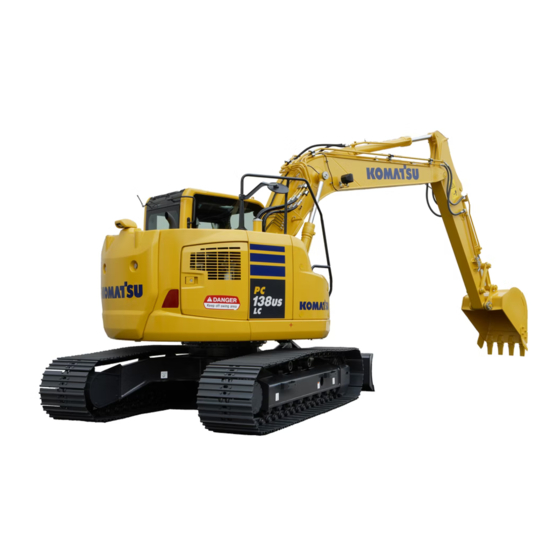
PC138US
PC138USLC
SERIAL NUMBERS
NOTICE
WARNING
TEN00189-01
-8
-8
PC138US-
20001
PC138USLC- 20001
and up
Advertisement
Chapters
Table of Contents

Related Manuals for Komatsu PC138USLC


Summary of Contents for Komatsu PC138USLC
- Page 1 20001 SERIAL NUMBERS and up PC138USLC- 20001 NOTICE Komatsu has Operation & Maintenance Manuals written in some other languages. if a foreign language manual is necessary, contact your local distributor for availability. WARNING Unsafe Use of this machine may cause serious injury or Death.Operators and maintenance personnel must read...
- Page 2 1 - 1...
- Page 3 In case this manual should be lost or damaged, immediately contact Komatsu or your Komatsu distributor to obtain a new copy. When you sell the machine, make sure that this manual should be provided to the new owner together with the machine.
-
Page 4: Foreword 1
FOREWORD FOREWORD 1 - 3... -
Page 5: Engine Dateplate
FOREWORD FOREWORD 1 - 4... -
Page 6: Safety Information 1
FOREWORD SAFETY INFORMATION SAFETY INFORMATION To enable you to use this machine safely, safety precautions and labels are given in this manual and affixed to the machine to give explanations of situations involving potential hazards and of the methods of avoiding such situations. - Page 7 Continuing improvements in the design of this machine can lead to changes in detail which may not be reflected in this manual. Consult Komatsu or your Komatsu distributor for the latest available information of your machine or for questions regarding information in this manual.
-
Page 8: Introduction 1
BREAKING-IN THE NEW MACHINE NOTICE Your Komatsu machine has been thoroughly adjusted and tested before shipment from the factory. However, operating the machine under full load before breaking the machine in can adversely affect the performance and shorten the machine life. -
Page 9: Product Information 1
FOREWORD PRODUCT INFORMATION PRODUCT INFORMATION When requesting service or ordering replacement parts, please inform your Komatsu distributor of the following items. PRODUCT IDENTIFICATION NUMBER (PIN)/MACHINE SERIAL NO. PLATE On the bottom right of the operator's cab The design of the nameplate differs according to the territory. -
Page 10: Service Meter Location 1
FOREWORD PRODUCT INFORMATION SERVICE METER LOCATION On top of the machine monitor YOUR MACHINE SERIAL NUMBERS AND DISTRIBUTOR Machine serial No. Engine serial No. Product identification number (PIN) Distributor name Address Service Personnel Phone/Fax 1 - 9... -
Page 11: Table Of Contents
FOREWORD CONTENTS CONTENTS FOREWORD FOREWORD SAFETY INFORMATION INTRODUCTION DIRECTIONS OF MACHINE BREAKING-IN THE NEW MACHINE PRODUCT INFORMATION PRODUCT IDENTIFICATION NUMBER (PIN)/MACHINE SERIAL NO. PLATE EPA REGULATIONS, ENGINE NUMBER PLATE SERVICE METER LOCATION YOUR MACHINE SERIAL NUMBERS AND DISTRIBUTOR SAFETY SAFETY SAFETY LABELS LOCATION OF SAFETY LABELS SAFETY LABELS... -
Page 12: Foreword
FOREWORD CONTENTS TOOL BOX 3-112 GREASE PUMP HOLDER 3-112 CUP HOLDER 3-112 ASHTRAY 3-113 FIRE EXTINGUISHER 3-113 MACHINE OPERATIONS AND CONTROLS 3-114 BEFORE STARTING ENGINE 3-114 STARTING ENGINE 3-133 AFTER STARTING ENGINE 3-138 STOPPING THE ENGINE 3-149 MACHINE OPERATION 3-150 STEERING THE MACHINE 3-154 SWINGING... - Page 13 WEAR PARTS LIST RECOMMENDED FUEL, COOLANT, AND LUBRICANT USE OF FUEL, COOLANT AND LUBRICANTS ACCORDING TO AMBIENT TEMPERATURE 4- 10 RECOMMENDED BRANDS, RECOMMENDED QUALITY FOR PRODUCTS OTHER THAN KOMATSU GENUINE OIL 4- 11 TIGHTENING TORQUE SPECIFICATIONS 4- 12 TIGHTENING TORQUE LIST...
- Page 14 2 - 1...
-
Page 15: Safety Information
SAFETY SAFETY SAFETY SAFETY LABELS LOCATION OF SAFETY LABELS SAFETY LABELS SAFETY INFORMATION Safety rules 2- 13 If problems are found 2- 13 Working wear and personal protective items 2- 13 Fire extinguisher and first aid kit 2- 13 Safety equipment 2- 13 Keep machine clean 2- 14... - Page 16 SAFETY SAFETY SAFETY MACHINE OPERATION 2- 22 STARTING ENGINE 2- 22 Checks before starting engine 2- 22 Safety rules for starting engine 2- 23 Starting engine in cold weather 2- 23 OPERATION 2- 24 Checks before operation 2- 24 Safety rules for changing machine directions 2- 24 Safety rules for traveling 2- 25...
-
Page 17: Safety Labels
If the labels are damaged, lost, or cannot be read properly, replace them with new ones. For details of the part numbers for the labels, see this manual or the actual label, and place an order with Komatsu distributor. 2 - 4... -
Page 18: Location Of Safety Labels
SAFETY SAFETY LABELS LOCATION OF SAFETY LABELS 2 - 5... -
Page 19: Safety Labels
SAFETY SAFETY LABELS SAFETY LABELS (1) Caution before operating or maintaining machine (09651-03001) (2) Caution before operating (09802-03000) (3) Caution for leaving operator's seat (09654-03001) 2 - 6... - Page 20 SAFETY SAFETY SAFETY LABELS SAFETY LABELS (4) Caution for going close to electric cables (09801-03001) (5) Caution for operating pattern (09822-03000) Standard machine 2 - 7...
- Page 21 SAFETY SAFETY SAFETY LABELS SAFETY LABELS (6) Caution when opening or closing front window (09839-03000) (7) Caution when stowing front window (09803-03000) (8) Caution when window comes out or breaks (20U-98-21910) (9) Caution with high-temperature coolant (09668-03001) 2 - 8...
- Page 22 SAFETY SAFETY SAFETY LABELS SAFETY LABELS (10) Caution with high-temperature hydraulic oil (09653-03001) (11) Caution when handling accumulator (09659-53000) (12) Caution when adjusting track tension (09657-03003) (13) Caution when handling cable (09808-03000) (14) Caution when handling battery (09664-30082) 2 - 9...
- Page 23 SAFETY SAFETY SAFETY LABELS SAFETY LABELS (15) Stop rotation during inspection and maintenance (09667-03001) (16) Caution against falling (09805-03000) (17) Caution against falling (09805-13000) (18) Prohibition to enter swing range (09133-23000) (19) Jump start prohibited (09842-A0481) This safety label is fixed to the engine starting motor. 2 - 10...
- Page 24 SAFETY SAFETY SAFETY LABELS SAFETY LABELS (20) Caution for control pattern (21W-98-44220) Machine equipped with control pattern selector valve (21) Caution when changing control pattern (22M-98-11180) Machine equipped with control pattern selector valve (22) Caution for high-pressure fuel (6217-71-9331) 2 - 11...
- Page 25 SAFETY SAFETY SAFETY LABELS SAFETY LABELS (23) Caution for high temperature (09817-A0753) (24) Caution when swinging or traveling in reverse The safety labels, (1) through (6) are a single seal. In replacement, place an order for it with Part No. 22U-00-21290. 2 - 12...
-
Page 26: General Precautions
SAFETY GENERAL PRECAUTIONS GENERAL PRECAUTIONS SAFETY RULES Only trained and authorized personnel can operate and maintain the machine. Follow all safety rules, precautions and instructions when operating or performing maintenance on the machine. If you are under the influence of alcohol or medication, your ability to safely operate or repair your machine may be severly impaired putting yourself and everyone else on your jobsite in danger. -
Page 27: Keep Machine Clean
SAFETY GENERAL PRECAUTIONS KEEP MACHINE CLEAN If water gets into the electrical system, there is a hazard that it will cause malfunctions or misoperation. Do not use water or steam to wash the electrical system (sensors, connectors). If inspection and maintenance is carried out when the machine is still dirty with mud or oil, there is a hazard that you will slip and fall, or that dirt or mud will get into your eyes. -
Page 28: Handrails And Steps
SAFETY GENERAL PRECAUTIONS HANDRAILS AND STEPS To prevent personal injury caused by slipping or falling off the machine, always do as follows. Use the handrails and steps marked by arrows in the diagram on the right when getting on or off the machine. To ensure safety, always face the machine and maintain three-point contact (both feet and one hand, or both hands and one foot) with the handrails and steps (including the track shoe) -
Page 29: Do Not Get Caught In Articulated Portion
SAFETY GENERAL PRECAUTIONS DO NOT GET CAUGHT IN ARTICULATED PORTION The clearance around the work equipment will change according to the movement of the link. If you get caught, this may lead to serious personal injury. Do not allow anyone to approach any rotating or telescoping part. BURN PREVENTION Hot coolant To prevent burns from hot water or steam spurting out when... -
Page 30: Fire Prevention And Explosion Prevention
SAFETY GENERAL PRECAUTIONS FIRE PREVENTION AND EXPLOSION PREVENTION Fire caused by fuel or oil Fuel, oil, antifreeze, and window washer liquid are particularly flammable and can be hazardous. To prevent fire, always observe the following: Do not smoke or use any flame near fuel or oil. Stop the engine before refueling. -
Page 31: Windshield Washer Fluid
Always contact your Komatsu distributor for advice. ATTACHMENT INSTALLATION When installing optional parts or attachments, there may be problems with safety or legal restrictions. Therefore contact your Komatsu distributor for advice. -
Page 32: Unauthorized Modifications
GENERAL PRECAUTIONS UNAUTHORIZED MODIFICATIONS If this machine is modified without permission from Komatsu, there is danger that problems may occur with safety and that this may lead to serious personal injury. Modifications may have an adverse effect on items such as machine strength and visibility. -
Page 33: Ensure Good Visibility
If there is any problem with the camera and the rear view cannot be displayed, contact your Komatsu distributor as soon as possible and ask for repairs to be carried out. -
Page 34: Signalman's Signal And Signs
Do not allow other persons to approach during the operation. Always observe the rules and regulations for the work site and environmental standards. This machine does not use asbestos, but there is a danger that imitation parts may contain asbestos, so always use genuine Komatsu parts. 2 - 21... -
Page 35: Safety Machine Operation
SAFETY SAFETY MACHINE OPERATION SAFETY MACHINE OPERATION STARTING ENGINE If there is a warning tag hanging from the work equipment control lever, do not start the engine or touch the levers. CHECKS BEFORE STARTING ENGINE Carry out the following checks before starting the engine at the beginning of the day's work. Remove all dirt from the surface of the window glass to ensure a good view. -
Page 36: Safety Rules For Starting Engine
SAFETY SAFETY MACHINE OPERATION SAFETY RULES FOR STARTING ENGINE Start and operate the machine only while seated. Do not attempt to start the engine by short-circuiting the engine starting circuit. Such an act may cause a serious bodily injury or fire. When starting the engine, sound the horn as a warning. -
Page 37: Operation
SAFETY SAFETY MACHINE OPERATION OPERATION CHECKS BEFORE OPERATION When carrying out the checks, move the machine to a wide area where there are no obstructions, and operate slowly. Do not allow anyone near the machine. Always fasten your seat belt. Check that the movement of the machine matches the display on the control pattern card. -
Page 38: Safety Rules For Traveling
SAFETY SAFETY MACHINE OPERATION SAFETY RULES FOR TRAVELING It is dangerous to drive too fast, or to start suddenly, stop suddenly, or to turn sharply. When traveling on level ground, keep the work equipment at a height of 40 to 50 cm (16 to 20 in) from the ground. If the work equipment blocks the view and it is difficult to travel in safety, raise the work equipment to a greater height. -
Page 39: Traveling On Slopes
SAFETY SAFETY MACHINE OPERATION TRAVELING ON SLOPES To prevent the machine from tipping over or slipping to the side, always do as follows. Keep the work equipment approx. 20 to 30 cm (8 to 12 in) above the ground. In case of emergency, lower the work equipment to the ground immediately to help stop the machine. -
Page 40: Operations On Slopes
SAFETY SAFETY MACHINE OPERATION OPERATIONS ON SLOPES When working on slopes, there is a hazard that the machine may lose its balance and turn over when the swing or work equipment are operated. This may lead to serious injury or property damage, so always provide a stable place when carrying out these operations, and operate carefully. - Page 41 SAFETY SAFETY SAFETY MACHINE OPERATION SAFETY MACHINE OPERATION Do not carry out demolition work under the machine. There is a hazard that the machine may become unstable and tip over. When working on or from the top of buildings or other structures, check the strength and the structure before starting operations.
-
Page 42: Operations On Snow
SAFETY SAFETY MACHINE OPERATION OPERATIONS ON SNOW Snow-covered or frozen surfaces are slippery, so be extremely careful when traveling or operating the machine, and do not operate the levers suddenly. Even a slight slope may cause the machine to slip, so be particularly careful when working on slopes. -
Page 43: Transportation
SAFETY MACHINE OPERATION TRANSPORTATION The machine can be divided into parts for transportation, so when transportating the machine, please contact your Komatsu distributor to have the work carried out. LOADING AND UNLOADING When loading or unloading the machine, mistaken operation may bring the hazard of the machine tipping over or falling, so particular care is necessary. -
Page 44: Battery
SAFETY SAFETY MACHINE OPERATION BATTERY BATTERY HAZARD PREVENTION Battery electrolyte contains sulphuric acid, and batteries generate flammable hydrogen gas, which may explode. Mistaken handling can lead to serious injury or fire. For this reason, always observe the following precautions. Do not use or charge the battery if the battery electrolyte level is below the LOWER LEVEL line. This may cause an explosion. -
Page 45: Starting Engine With Booster Cables
SAFETY SAFETY MACHINE OPERATION STARTING ENGINE WITH BOOSTER CABLES If any mistake is made in the method of connecting the booster cables, it may cause the battery to explode, so always do as follows. When starting with a booster cable, carry out the starting operation with two workers (one worker sitting in the operator's seat and the other working with the battery). -
Page 46: Towing
SAFETY SAFETY MACHINE OPERATION TOWING SAFETY RULES FOR TOWING Serious injury or death could result if a disabled machine is towed incorrectly or if there is a mistake in the selection or inspection of the wire rope. For towing, see "TOWING THE MACHINE (PAGE 3-194)". Always be sure to check carefully that the capacity of the wire rope used for towing is ample for the weight of the towed machine. -
Page 47: Lifting Objects With Bucket
SAFETY SAFETY MACHINE OPERATION LIFTING OBJECTS WITH BUCKET SAFETY RULES FOR LIFTING OBJECTS Determine the signals to be used and place a signalman in position. To prevent the machine from tipping over or falling, carry out the operation on flat ground. To prevent the danger of contact with a raised load or the danger from a falling load, do not allow any worker inside the area. -
Page 48: Safety Maintenance Information
SAFETY SAFETY MAINTENANCE INFORMATION SAFETY MAINTENANCE INFORMATION WARNING TAG Always attach the "DO NOT OPERATE" warning tag to the work equipment control lever in the operator's cab to alert others that you are performing service or maintenance on the machine. Attach additional warning tags around the machine if necessary. -
Page 49: Stop Engine Before Carrying Out Maintenance
SAFETY SAFETY MAINTENANCE INFORMATION STOP ENGINE BEFORE CARRYING OUT MAINTENANCE Stop the machine on firm, level ground. Select a place where there is no hazard of falling rocks or landslides, or of flooding if the land is low. Lower the work equipment completely to the ground and stop the engine. -
Page 50: Two Workers For Maintenance When Engine Is Running
SAFETY SAFETY MAINTENANCE INFORMATION TWO WORKERS FOR MAINTENANCE WHEN ENGINE IS RUNNING To prevent injury, do not carry out maintenance with the engine running. If maintenance must be carried out with the engine running, carry out the operation with at least two workers and do as follows. One worker must always sit in the operator's seat and be ready to stop the engine at any time. -
Page 51: Accumulator, Gas Spring
Do not make holes in it, weld it, or use a cutting torch. Do not hit or roll the accumulator, or subject it to any impact. When disposing of the accumulator, the gas must be released. Please contact your Komatsu distributor to have this work performed. PERSONNEL Only authorized personnel can service and repair the machine. -
Page 52: When Using Hammer
If it is disassembled by mistake, the spring will fly out and cause serious injury. When it becomes necessary to disassemble it, ask your Komatsu distributor to do the work. 2 - 39... -
Page 53: Safety Rules For High-Pressure Oil
If any loose bolts are found, stop work and tighten to the specified torque. If any damaged hoses are found, stop operations immediately and contact your Komatsu distributor. Replace the hose if any of the following problems are found. -
Page 54: Waste Materials
SAFETY SAFETY MAINTENANCE INFORMATION WASTE MATERIALS To prevent pollution, pay careful attention to the method of disposing of waste materials. Always put oil drained from your machine in containers. Never drain oil directly onto the ground or dump into the sewage system, rivers, the sea, or lakes. - Page 56 3 - 1...
-
Page 57: Machine View Illustrations
OPERATION MACHINE VIEW ILLUSTRATIONS MACHINE VIEW ILLUSTRATIONS OVERALL MACHINE VIEW Bucket Working lamp Bucket cylinder Sprocket (10) Track frame (11) Track shoe Arm cylinder Boom (12) Idler Boom cylinder (13) Blade cylinder (blade specification) Additional lamp (if equipped) (14) Blade (blade specification) 3 - 2... -
Page 58: Controls And Gauges
OPERATION MACHINE VIEW ILLUSTRATIONS CONTROLS AND GAUGES Radio (12) Fuel control dial Lock lever (13) Lamp switch Left work equipment control lever (14) Swing lock switch Travel pedals (15) Revolving warning lamp switch (if equipped) Travel levers (16) Roof glass wiper switch (if equipped) Horn switch (17) Attachment control pedal (if equipped) - Page 59 OPERATION MACHINE VIEW ILLUSTRATIONS Machine monitor AA: Screen for standard BB: Screen with all lamps lighted up CC: Maintenance time warning screen Wiper switch (15) Travel speed selector switch Buzzer cancel switch (16) Window washer switch Auto-deceleration switch (17) Air conditioner control switches Engine coolant temperature monitor (18) Engine oil pressure monitor...
-
Page 60: Detailed Controls And Gauges
OPERATION DETAILED CONTROLS AND GAUGES DETAILED CONTROLS AND GAUGES The following is an explanation of devices needed for operating the machine. To perform suitable operations correctly and safely, it is important to completely understand methods of operating the equipment, and the meanings of the displays. MONITORING SYSTEM AA: Screen for standard BB: Screen with all lamps lighted up... - Page 61 OPERATION DETAILED CONTROLS AND GAUGES Basic Operation of Machine Monitor Starting Engine When Situation is Normal When the starting switch is turned to the ON position, the opening screen GG is displayed. After the opening screen GG is displayed for 2 seconds, the screen switches to the check before starting screen After the check before starting screen DD is displayed for 2 seconds, the screen switches to the working mode/travel mode display screen HH.
- Page 62 OPERATION DETAILED CONTROLS AND GAUGES REMARK When the engine is started, the battery voltage may suddenly drop depending on the temperature and the battery condition. If this happens, the display on the machine monitor may momentarily go out, but this does not indicate any abnormality.
- Page 63 OPERATION DETAILED CONTROLS AND GAUGES If There Is Abnormality When Starting Engine If there is any abnormality when starting the engine, the check before starting screen DD changes to the maintenance interval warning screen CC, warning screen FF, or error screen EE. After displaying the check before starting screen DD for 2 seconds, the screen changes to the maintenance interval warning screen CC.
- Page 64 OPERATION DETAILED CONTROLS AND GAUGES If Any Abnormality Occurs During Operation If any abnormality occurs during operation, the standard screen BB changes to warning screen FF-(1) or the error screen EE. After displaying warning screen FF-(1) for 2 seconds, the screen automatically changes to warning screen FF-(2). 3 - 9...
- Page 65 OPERATION DETAILED CONTROLS AND GAUGES REMARK The colors lighting up the monitors related to the emergency stop items, caution items, and basic check items are as follows. AA: Screen for standard BB: Screen with all lamps lighted up CC: Maintenance time warning screen Color when monitor lights up Type of monitor When...
-
Page 66: Emergency Monitors
OPERATION DETAILED CONTROLS AND GAUGES Emergency Monitors CAUTION If the monitor lights up red, stop the engine immediately or run at low idle, check applicable location, then perform necessary actions. These items should be observed while the engine is running. If there is a problem, the monitor for the abnormal location lights up red and buzzer sounds, perform action immediately. - Page 67 OPERATION DETAILED CONTROLS AND GAUGES Hydraulic Oil Temperature Monitor This monitor (2) warns the operator that the hydraulic oil temperature has risen. If the hydraulic oil temperature becomes abnormally high, abnormality display (C) is shown. Stop operations and stop the engine or run it at low idling until the monitor changes to normal display (B).
-
Page 68: Caution Monitors
OPERATION DETAILED CONTROLS AND GAUGES Caution Monitors CAUTION If the warning monitor lights up red, stop operations as soon as possible and perform inspection and maintenance of the applicable location. If the warning is ignored, it may lead to failure. These are items that should be observed while the engine is running. - Page 69 OPERATION DETAILED CONTROLS AND GAUGES Hydraulic Oil Temperature Monitor If this monitor (2) shows low-temperature display (A), carry out the warm-up operation. For details, see "Hydraulic Equipment Warm Up (PAGE 3-141)". Carry out the warm-up operation for the hydraulic equipment until monitor (2) shows normal display (B).
- Page 70 OPERATION DETAILED CONTROLS AND GAUGES Basic Check Monitors CAUTION These monitors do not guarantee the condition of the machine. Do not simply rely on the monitor when carrying out checks before starting (daily inspection). Always get off the machine and check each item directly.
- Page 71 REMARK For details of the method of confirming the maintenance interval, see "Maintenance Selector Switch (PAGE 3-38)". If it is desired to change settings for the maintenance interval, have your Komatsu distributor change the settings. 3 - 16...
- Page 72 OPERATION DETAILED CONTROLS AND GAUGES Meter Display Portion Pilot display Gauge and Meter Engine pre-heating monitor (10) Engine coolant temperature gauge Swing lock monitor (11) Hydraulic oil temperature gauge Wiper monitor (12) Fuel gauge Auto-deceleration monitor (13) Service meter, clock Working mode monitor (14) ECO gauge...
- Page 73 OPERATION DETAILED CONTROLS AND GAUGES Swing Lock Monitor This monitor (2) informs the operator that the swing lock is being actuated. Actuated: Lights up When the swing lock switch is turned ON (ACTUATED), the monitor lamp lights up. This lamp lights up when the swing parking brake release switch is set to the FREE position.
- Page 74 Monitor off: Air conditioner OFF Message Monitor This monitor (8) lights up to inform the operator that a message has been received from Komatsu. To read the message, see "Message Display (PAGE 3-55)" for details. Lighted up green: There is unread message...
- Page 75 OPERATION DETAILED CONTROLS AND GAUGES Idle Stop Guidance If the levers are not operated for more than five minutes, and the engine is idling, the idling stop message is displayed on the monitor. When waiting for work or stopping work for a short periods, stop the engine to reduce unnecessary fuel consumption.
- Page 76 OPERATION DETAILED CONTROLS AND GAUGES Hydraulic Oil Temperature Gauge This meter (11) shows the hydraulic oil temperature. During normal operations, the indicator should be in the green range. If the indicator enters the red range (A) during operations, the hydraulic oil temperature is 102°C (215.6°F) or more. Run the engine at low idling or stop it and wait for the hydraulic oil temperature to go down.
- Page 77 OPERATION DETAILED CONTROLS AND GAUGES Service Meter, Clock This meter (13) shows the total hours of operation of the machine or the present time. When the engine is running, the service meter advances even if the machine is not moving. The service meter advances 1 for every hour that the machine is working, regardless of the engine speed.
- Page 78 OPERATION DETAILED CONTROLS AND GAUGES ECO Gauge This gauge (14) shows the working load status. When the gauge is in green range A, the work load is light to medium. When the gauge is in orange range B), the load is heavy. When the gauge enters the orange range, there is no abnormality on the machine, but to protect the environment, reduce the engine output to a point where there is no adverse...
- Page 79 OPERATION DETAILED CONTROLS AND GAUGES Monitor Switches Portion Working mode selector switch Window washer switch Auto-deceleration switch Buzzer cancel switch Travel speed selector switch Function switches Wiper switch Air conditioner switch 3 - 24...
- Page 80 For details of the method for handling machines ready for attachment, see the ATTACHMENTS AND OPTIONS Section. If you want to have automatic setting of the P, E, L, B or ATT mode when starting (optional default setting), please ask your Komatsu distributor to change the setting. 3 - 25...
- Page 81 OPERATION OPERATION DETAILED CONTROLS AND GAUGES DETAILED CONTROLS AND GAUGES Procedure for operation 1. If working mode selector switch (1) is pressed, the Working Mode screen is displayed on the monitor. 2. Press function switches F3 or F4 at the bottom of the screen or working mode selector switch (1) to change the mode selection one at a time.
- Page 82 OPERATION DETAILED CONTROLS AND GAUGES Auto-deceleration Switch If the control levers are at neutral, this switch (2) automatically lowers the engine speed and turns on the function to reduce fuel consumption. Auto-deceleration monitor ON: Auto-deceleration ON Auto-deceleration monitor OFF: Auto-deceleration OFF Each time the switch is pressed, the auto-deceleration is switched between ON and OFF.
- Page 83 OPERATION DETAILED CONTROLS AND GAUGES Travel Speed Selector Switch WARNING When loading or unloading the machine on a trailer, always travel at low speed (set to Lo). Never operate the travel speed selector switch when traveling. If the Hi-Lo switch is operated when the machine is traveling, the machine may deviate to one side even when it is traveling in a straight line.
- Page 84 OPERATION DETAILED CONTROLS AND GAUGES Wiper Switch This switch (4) actuates the front window wiper. Each time the switch is pressed, it changes ON → INT → stop (OFF). Wiper monitor INT lighted up: Wiper operates intermittently Wiper monitor ON lighted up: Wiper operates continuously Wiper monitor OFF: Wiper stops REMARK Each time wiper switch (4) is pressed, the mode is displayed in the...
- Page 85 OPERATION DETAILED CONTROLS AND GAUGES Window Washer Switch This switch (5) is kept continuously pressed, window washer fluid is sprayed out on the front glass. When the switch is released, the spray stops. If switch (5) is kept pressed when the wiper is stopped, the window washer fluid will spray, and at the same time, the wiper will be actuated continuously.
- Page 86 OPERATION DETAILED CONTROLS AND GAUGES Function Switches Function switches (7) consist of 6 switches (F1 to F6). The function of each switch differs according to the content of each screen. When the monitor display shows the standard screen, the functions are displayed as follows. F3: Camera screen selector switch (if equipped) F4: Service meter/time display selector switch F5: Maintenance mode switch...
-
Page 87: Handling Function Switches
OPERATION DETAILED CONTROLS AND GAUGES Handling Function Switches The function switches (A) at the bottom of the monitor display consist of 6 switches (F1 - F6). The function of each switch differs according to the content of each screen. The function of switches (A) on each screen can be confirmed by guidance icons (B) displayed on top of each switch. - Page 88 OPERATION DETAILED CONTROLS AND GAUGES Operating Camera Screen Display The following explains the method used to display the camera image on the monitor. On the standard screen, if switch F3 is pressed, the image display screen is displayed. Press switch F5 to return to the standard screen. 3 - 33...
- Page 89 OPERATION DETAILED CONTROLS AND GAUGES Other Mode Operations When Displaying Camera Image Even during the camera display, it is possible to operate other modes. The air conditioner can be operated. If the air conditioner switch is operated, the screen switches to the air conditioner control screen.
- Page 90 OPERATION OPERATION DETAILED CONTROLS AND GAUGES DETAILED CONTROLS AND GAUGES Press the auto-deceleration switch to turn the auto-deceleration function ON/OFF. Even if the auto-deceleration switch is pressed, the camera image display screen does not switch to another screen or return to the standard screen display. It is possible to press the buzzer cancel switch to stop the alarm buzzer for the warning item where there is an abnormality.
- Page 91 OPERATION DETAILED CONTROLS AND GAUGES Action When Warning is Generated When Displaying Camera Image If an error or alarm occurs while the camera image is being displayed, the error monitor or alarm monitor is displayed at the top left of the screen and flashes. If the error monitor or alarm monitor is displayed, press switch F6, return to the standard screen, and check the content of the error or alarm display.
- Page 92 OPERATION DETAILED CONTROLS AND GAUGES Service Meter/Clock Display Selector Switch On the standard screen, it is possible to press switch F4 to switch the service meter and clock display at the top of the monitor display. When the time is being displayed, press switch F4 to switch to the service meter display.
-
Page 93: Maintenance Selector Switch
OPERATION DETAILED CONTROLS AND GAUGES Maintenance Selector Switch When switch F5 is pressed on the standard screen, the monitor display screen switches to the maintenance mode screen. The items on the maintenance display are as follows. Engine oil change Engine oil filter change Fuel main filter change 1000 Fuel pre-filter change... - Page 94 If the time remaining until maintenance becomes 0 hours, the remaining time display is highlighted in red. If you want to change the setting for the maintenance interval, please consult your Komatsu distributor. 3 - 39...
- Page 95 OPERATION DETAILED CONTROLS AND GAUGES Operations on Maintenance Interval Reset Screen On the maintenance list screen, if switch F6 is kept pressed for at least 1.5 seconds, the screen changes to the maintenance time reset screen. Reset the remaining time on this screen. 1.
- Page 96 OPERATION DETAILED CONTROLS AND GAUGES User Mode Selector Switch When the switch F6 is pressed, the monitor display screen switches to the setting mode screen for the machine. On the User Menu screen, it is possible to carry out the following operations with switches F3 to F6.
- Page 97 OPERATION OPERATION DETAILED CONTROLS AND GAUGES DETAILED CONTROLS AND GAUGES F5: Returns to standard screen. F6: Switches to setting screen for selected item. If no switch is operated for 30 seconds on the user menu screen, the screen automatically returns to the previous screen. The following items can be set.
- Page 98 OPERATION DETAILED CONTROLS AND GAUGES Breaker/Attachment Setting On machines ready for attachment, it is possible on the breaker/attachment setting menu to adjust the oil flow in B mode and ATT mode to match the attachment. For machines that have no attachment, the breaker/attachment setting mode is not displayed.
- Page 99 OPERATION OPERATION DETAILED CONTROLS AND GAUGES DETAILED CONTROLS AND GAUGES 3. On the working mode selection screen shown on the right, select B Breaker and press switch F6. On the working mode selection screen shown on the right, it is possible to carry out the following operations with switches F3 to F6.
- Page 100 OPERATION OPERATION DETAILED CONTROLS AND GAUGES DETAILED CONTROLS AND GAUGES On the Breaker Select Menu screen, it is possible to carry out the following operations with switches F3 - F6. F3: Moves to next item (1 line down). F4: Moves to previous item (1 line up). F5: Returns to previous screen.
- Page 101 OPERATION OPERATION DETAILED CONTROLS AND GAUGES DETAILED CONTROLS AND GAUGES 2. On the Breaker Select screen, select one of the two set values for the oil flow, then press switch F6. The default values for the flow setting are both set to 130 liter/min, as shown in the illustration on the right.
- Page 102 OPERATION DETAILED CONTROLS AND GAUGES Changing breaker flow setting 1. Select breaker flow setting (b) on the Breaker Select Menu screen, then press switch F6. 2. On the Breaker Oil Flow Setting screen, select one of the two set values for the oil flow, then press switch F6. The default values for the oil flow setting are both set to 130 liter/min, as shown in the illustration on the right.
- Page 103 OPERATION OPERATION DETAILED CONTROLS AND GAUGES DETAILED CONTROLS AND GAUGES On the Breaker Select Menu and Breaker Oil Flow Setting screen, it is possible to carry out the following operations with switches F3 - F6. F3: Moves to next item (1 line down). F4: Moves to previous item (1 line up).
- Page 104 OPERATION DETAILED CONTROLS AND GAUGES Changing Attachment Mode Setting 1. On the standard screen, press switch F6. 2. Select Breaker/Attachment Settings on the user menu, then press switch F6. 3 - 49...
- Page 105 OPERATION OPERATION DETAILED CONTROLS AND GAUGES DETAILED CONTROLS AND GAUGES 3. On the working mode selection screen shown on the right, select ATT 2-Way Attachment, then press switch F6. On the working mode selection screen shown on the right, it is possible to carry out the following operations with switches F3 to F6.
- Page 106 OPERATION OPERATION DETAILED CONTROLS AND GAUGES DETAILED CONTROLS AND GAUGES On the 2-Way Attachment Select Menu screen, it is possible to carry out the following operations with switches F3 - F6. F3: Moves to next item (1 line down). F4: Moves to previous item (1 line up). F5: Returns to previous screen.
- Page 107 OPERATION OPERATION DETAILED CONTROLS AND GAUGES DETAILED CONTROLS AND GAUGES 2. On the 2-Way Attachment Select Menu, select one of the two set values for the oil flow, then press switch F6. The default values for the oil flow setting are both set to 225 liters/min, as shown in the illustration on the right.
- Page 108 OPERATION DETAILED CONTROLS AND GAUGES Changing attachment flow setting 1. Select 2-Way Attachment Oil Flow Setting (b) on the 2-Way Attachment Select menu screen, then press switch F6. 2. On the 2-Way Attachment Select Oil Flow Setting screen, select one of the two set values for the oil flow, then press switch F6.
- Page 109 OPERATION OPERATION DETAILED CONTROLS AND GAUGES DETAILED CONTROLS AND GAUGES On the 2-Way Attachment Select Menu screen and 2-Way Attachment Select Menu screen, it is possible to carry out the following operations with switches F3 - F6. F3: Moves to next item (1 line down). F4: Moves to previous item (1 line up).
- Page 110 (Machines equipped with KOMTRAX) On machines equipped with KOMTRAX, it is possible to see the messages from your Komatsu distributor on this message display menu. When there are any messages, the messages monitor at the top left of the monitor standard screen lights up.
- Page 111 OPERATION OPERATION DETAILED CONTROLS AND GAUGES DETAILED CONTROLS AND GAUGES 2. Select "User Message" on the User Menu, then press switch If you press switch F5, the screen returns to the user menu screen. 3. "No message" is displayed on the screen. Press switch F5 to return to the standard screen.
- Page 112 OPERATION DETAILED CONTROLS AND GAUGES Adjusting Screen Use this screen adjustment menu to adjust the brightness, contrast, and back light of the screen. 1. On the standard screen, press switch F6. 2. Select screen adjustment on the user menu, then press switch F6.
- Page 113 OPERATION OPERATION DETAILED CONTROLS AND GAUGES DETAILED CONTROLS AND GAUGES 3. Select item to be adjusted (a) or (b) from the selection menu screen for screen adjustment, then press switch F6. The screen switches to the setting screen for the selected item. (a): Standard screen adjustment (b): Camera screen adjustment (only machines equipped with camera)
- Page 114 OPERATION OPERATION DETAILED CONTROLS AND GAUGES DETAILED CONTROLS AND GAUGES On the screen for Items 1) and 2), it is possible to carry out the following operations with switches F2 to F6. F2: Resets all adjusted values to default value F3: Indicator of selected item moves 1 segment to left.
- Page 115 OPERATION DETAILED CONTROLS AND GAUGES Clock Adjustment On this clock adjustment menu, it is possible to change the setting of the clock displayed on the pilot monitor of the standard display. 1. On the standard screen, press switch F6. 3 - 60...
- Page 116 OPERATION OPERATION DETAILED CONTROLS AND GAUGES DETAILED CONTROLS AND GAUGES 2. Select "Clock Adjustment" on the user menu, then press switch F6. The screen switches to the time adjustment selection menu screen. The following three items can be changed. (a) Clock setting (b) 12/24 hour display mode (c) Daylight saving time 3 - 61...
- Page 117 OPERATION DETAILED CONTROLS AND GAUGES 3. On the clock adjustment selection screen, it is possible to carry out the following operations with switches F3 to F6. Time Adjust the hour setting. 1) If "Time" (a) is not highlighted in yellow, press switch F6 to highlight "Time"...
- Page 118 OPERATION OPERATION DETAILED CONTROLS AND GAUGES DETAILED CONTROLS AND GAUGES 2) When minute display (c) is highlighted in orange, operate the switches as follows to adjust minute display (c). If it is not necessary to change the minute setting, press switch F6.
- Page 119 OPERATION OPERATION DETAILED CONTROLS AND GAUGES DETAILED CONTROLS AND GAUGES Daylight Saving Time (Summer time) 1) If daylight saving time is turned ON (a), the clock display becomes 1 hour earlier. If daylight saving time is turned OFF (b), the clock display returns to the set time. The selected display mode is highlighted in green.
- Page 120 OPERATION DETAILED CONTROLS AND GAUGES Language Selection On this language selection menu, it is possible to select the language used on the monitor display. The languages that can be selected are as follows. Japanese, English, Chinese, French, Spanish, Portuguese, Italian, German, Russian, Turkish, Indonesian, Thai 1.
- Page 121 OPERATION OPERATION DETAILED CONTROLS AND GAUGES DETAILED CONTROLS AND GAUGES 3. Select the language to use for the display, then press switch F6. The screen display changes to the selected language. On the language selection screen, it is possible to carry out the following operations with switches F3 to F6.
- Page 122 OPERATION OPERATION DETAILED CONTROLS AND GAUGES DETAILED CONTROLS AND GAUGES 2. Select "Economy Mode Adjustment" on the user menu, then press switch F6. The screen switches to the economy mode adjustment selection menu screen. 3. Select the desired E mode from the economy mode adjustment selection menu.
-
Page 123: Switches
OPERATION DETAILED CONTROLS AND GAUGES SWITCHES Starting switch Room lamp switch Fuel control dial Emergency pump drive switch Cigarette lighter Swing parking brake releasel switch Swing lock switch (10) Revolving warning lamp switch (if equipped) Lamp switch (11) Roof glass wiper switch (if equipped) Horn switch Starting Switch Starting switch (1) is used to start or stop the engine. - Page 124 OPERATION DETAILED CONTROLS AND GAUGES (D): HEAT position Set to this position when starting the engine in cold weather. When the starting key is turned to HEAT position (D), the preheating monitor lights up. Keep the key in this position until the preheating monitor flashes.
- Page 125 OPERATION DETAILED CONTROLS AND GAUGES Swing Lock Switch WARNING When not using the swing operation, e.g. when traveling, put the swing lock switch to the OFF position. On slopes, even when the swing lock switch is at the ON position, the weight of the work equipment may cause the upper structure to swing if the swing control lever is operated in the downhill direction.
- Page 126 OPERATION DETAILED CONTROLS AND GAUGES Room Lamp Switch NOTICE It is possible to turn on the interior cab room lamp even when starting switch is in the OFF position, do not forget to turn it off. Use this switch (7) to light up the room lamp. (a) ON position: Lamp lights up (b) OFF position: Lamp goes out The room lamp lights up even when the starting switch is at the...
- Page 127 OPERATION DETAILED CONTROLS AND GAUGES Revolving Warning Lamp Switch (If equipped) Use this switch (10) to light up the yellow rotating lamp on top of the cab. (a) ON: Lamps light up (b) OFF: Lamps go off Roof Glass Wiper Switch (If equipped) Use this switch (11) to operate the wiper and spray out washer fluid for the glass in the cab roof.
-
Page 128: Control Levers And Pedals
OPERATION DETAILED CONTROLS AND GAUGES CONTROL LEVERS AND PEDALS Lock lever Right work equipment control lever Travel levers (with auto-deceleration system) (with pedal and auto-deceleration system) Blade control lever (blade specification) Left work equipment control lever (with auto-deceleration system) 3 - 73... - Page 129 OPERATION DETAILED CONTROLS AND GAUGES Lock Lever WARNING When leaving the operator's compartment, set the lock lever securely to the LOCK position. If the lock lever is not at the LOCK position and the control levers or control pedals are touched by mistake, it may lead to serious personal injury. Check that the condition of the lever is as shown in the diagram.
- Page 130 OPERATION DETAILED CONTROLS AND GAUGES Travel Levers WARNING Do not rest your foot on the pedal. If you carry out operations with your foot on the pedal, the machine may suddenly start if pressure is applied by mistake to the pedal, and this may lead to serious personal injury. Be extremely careful when using the pedal for travel and steering operations, and do not put your foot on the pedal when it is not necessary.
- Page 131 OPERATION DETAILED CONTROLS AND GAUGES Work Equipment Control Lever This left work equipment control lever (3) is used to operate the arm and upper structure. Swing operation (a) Swing to right (b) Swing to left Arm operation (c) Arm IN (d) Arm OUT N (Neutral): The upper structure and arm are held in that position when they come to a stop and do not move.
-
Page 132: Sun Roof
OPERATION DETAILED CONTROLS AND GAUGES SUN ROOF WARNING When leaving the operator's seat, set the lock lever securely to the LOCK position. If the lock lever is at the FREE position and the control levers or control pedals is touched by mistake, this may lead to a serious accident. - Page 133 OPERATION DETAILED CONTROLS AND GAUGES Opening 1. Stop the machine on level ground, lower the work equipment completely to the ground, then stop the engine. 2. Set the lock lever (1) securely to the LOCK position (L). 3. Check that the wiper blade is stowed in the right stay. 4.
- Page 134 OPERATION OPERATION DETAILED CONTROLS AND GAUGES DETAILED CONTROLS AND GAUGES 5. Hold lower knob (C) with your left hand from inside the operator's cab, and with your right hand, grip top knob (D), pull it up, and push it against lock catch (E) at the rear of the cab securely to lock the window.
- Page 135 OPERATION DETAILED CONTROLS AND GAUGES Closing WARNING When closing the window, lower it slowly and be careful not to get your hand caught. 1. Stop the machine on level ground, lower the work equipment completely to the ground, then stop the engine. 2.
- Page 136 OPERATION OPERATION DETAILED CONTROLS AND GAUGES DETAILED CONTROLS AND GAUGES 5. When the bottom of the window reaches the top of the bottom window, push the top of the window to the front to push it against left and right lock catches (G) and engage the lock. 6.
- Page 137 OPERATION DETAILED CONTROLS AND GAUGES Removing Lower Windshield 1. Open the front window, then hold grip (1), pull up, and remove the bottom window. 2. After removing the bottom window, store it at the rear of the operator's cab and lock it securely with lock (2). The procedure for stowing is as follows.
-
Page 138: Sliding Door
OPERATION DETAILED CONTROLS AND GAUGES SLIDING DOOR CAUTION Be sure to check that the sliding door is locked in position both when it is open and when it is closed. Always stop the machine on level ground when opening or closing the door. -
Page 139: Emergency Escape Hammer
OPERATION DETAILED CONTROLS AND GAUGES EMERGENCY ESCAPE HAMMER CAUTION If it is necessary to break the window glass with the hammer, be extremely careful not to injure yourself on the flying pieces of broken glass. To prevent injury, remove the broken pieces of glass remaining in the frame before escaping through the window. Be careful also not to slip on the broken pieces of glass. -
Page 140: Cap With Lock
OPERATION DETAILED CONTROLS AND GAUGES CAP WITH LOCK Use the starting switch key to open and close the locks on the caps and covers. For details of the locations of the caps and covers with locks, see "LOCKING (PAGE 3-175)". Insert the key as far as it will go to the shoulder (A). -
Page 141: Engine Hood
OPERATION DETAILED CONTROLS AND GAUGES ENGINE HOOD CAUTION When carrying out inspection and maintenance inside the engine hood, always use the hood support lever to hold the engine hood open. NOTICE Always keep the hood locked except when opening it. 1. -
Page 142: Cab Rear Cover
OPERATION DETAILED CONTROLS AND GAUGES CAB REAR COVER CAUTION When carrying out inspection and maintenance inside the cover, always use the cover support lever to hold the cover open. NOTICE Except when opening the cover for some reason, always keep the cover locked. 1. -
Page 143: Pump Room Door, Battery Room Door
OPERATION DETAILED CONTROLS AND GAUGES PUMP ROOM DOOR, BATTERY ROOM DOOR CAUTION When carrying out inspection and maintenance inside the door, always use the stopper to hold the door open. NOTICE Always keep the door locked except when opening it. 1. -
Page 144: Door At Front Of Tool Box
OPERATION DETAILED CONTROLS AND GAUGES DOOR AT FRONT OF TOOL BOX CAUTION When carrying out inspection and maintenance inside the door, always use the stopper to hold the door open. NOTICE Always keep the door locked except when opening it. 1. -
Page 145: Air Conditioner Controls
OPERATION DETAILED CONTROLS AND GAUGES AIR CONDITIONER CONTROLS Air Conditioner Control Panel OFF switch FRESH/RECIRC selector switch Fan switch Display monitor Temperature control switch Air conditioner switch Vent selector switch Sunlight sensor Auto switch OFF Switch Switch (1) is used to stop the fan and air conditioner. REMARK Even if this switch (1) is pressed, the monitor screen does not switch to the air conditioner adjustment screen. - Page 146 OPERATION DETAILED CONTROLS AND GAUGES Fan Switch Switch (2) is used to adjust the air flow. The air flow can be adjusted to six levels. Press the E switch to increase the air flow; press the R switc h to decrease the air flow. During auto operation, the air flow is automatically adjusted.
- Page 147 OPERATION DETAILED CONTROLS AND GAUGES Vent Selector Switch Switch (4) is used to select the vents. When switch (4) is pressed, the display on monitor display (7) switches and air blows out from the vents displayed. During automatic operation, the vents are automatically selected.
- Page 148 OPERATION DETAILED CONTROLS AND GAUGES Auto Switch With switch (5), the air flow, vents, and air source (RECIRC/FRESH) are automatically selected according to the set temperature. Press switch (5), then use temperature control switch (3) to set the temperature, and run the air conditioner under automatic control.
- Page 149 OPERATION DETAILED CONTROLS AND GAUGES Air Conditioner Switch Switch (8) is used to turn the air conditioner (cooling, dehumidifying, heating) ON or OFF. Press air conditioner switch (8) when the fan is operating (when display (b) is shown on the display monitor). The air conditioner is switched ON and starts to work.
- Page 150 OPERATION DETAILED CONTROLS AND GAUGES Method of Operation The air conditioner can be operated automatically or manually. Select the method of operation as desired. Automatic Operation 1. Turn auto switch (5) ON. The monitors for the set temperature (a) and air flow (b) are also displayed.
- Page 151 OPERATION DETAILED CONTROLS AND GAUGES Stopping Automatic Operation Press OFF switch (1). Operation stops. Manual Operation 1. Press fan switch (2) and adjust the air flow. When doing this, check that temperature setting (a) and air flow (b) are displayed on monitor (7).
- Page 152 OPERATION OPERATION DETAILED CONTROLS AND GAUGES DETAILED CONTROLS AND GAUGES 3. Press temperature setting switch (3) and adjust temperature inside the cab. 4. Press vent selector switch (4) and select the desired vents. When this is done, the display for vent (c) of the display monitor changes according to the selection.
- Page 153 OPERATION DETAILED CONTROLS AND GAUGES Stopping Manual Operation Press OFF switch (1). Operation stops. Operation with Cold Air to Face and Warm Air to Feet To operate with cold air blowing to the face and warm air blowing to the feet, set as follows. 1.
- Page 154 OPERATION OPERATION DETAILED CONTROLS AND GAUGES DETAILED CONTROLS AND GAUGES 3. Turn air conditioner switch (8) ON. 4. Adjust fan switch (2), temperature setting switch (3) and RECIRC/FRESH selector switch (6) to the desired positions. 3 - 99...
- Page 155 OPERATION DETAILED CONTROLS AND GAUGES Defroster Operation 1. Press fan switch (2) and adjust the air flow. When doing this, check that temperature setting (a) and air flow (b) are displayed on monitor (7). 2. Press vent selector switch (4) and set vent display on the display monitor to (f) or (g) as shown in diagram on the right.
- Page 156 OPERATION OPERATION DETAILED CONTROLS AND GAUGES DETAILED CONTROLS AND GAUGES 3. Press RECIRC/FRESH selector switch (6) and set it to take in fresh air. 4. Press temperature setting switch (3) and set temperature on the display (7) monitor to maximum heating. 5.
- Page 157 If any abnormality is detected in any equipment or sensor used on the air conditioner, "A/C Controller Error" is displayed on the air conditioner monitor screen. If "A/C Controller Error" is displayed, please ask your Komatsu distributor to carry out inspection and repair. 3 - 102...
-
Page 158: Radio
OPERATION DETAILED CONTROLS AND GAUGES RADIO Control Panel Power switch, Volume control knob, Balance AS/PS button control knob Preset station buttons (1,2,3,4,5,6) SEL button Display FM/AM selection button Time reset button Display selection button Tuning button Power switch, Volume control knob, Balance control knob Press this knob (1) to turn the power for the radio on. - Page 159 OPERATION DETAILED CONTROLS AND GAUGES Display Selection Button (TIME) On this machine, priority is given to the frequency display. When the frequency is being displayed, press button (4) and the display will show the present time for 5 seconds. After 5 seconds pass, the display returns automatically to the frequency display.
- Page 160 OPERATION DETAILED CONTROLS AND GAUGES Controls of Radio Method of Setting with Preset Button 1. Press power switch (1) and display the frequency on display (7). 2. Use tuning button (9) to set to the desired frequency. There are two methods for tuning: auto tuning and manual tuning. 3.
- Page 161 OPERATION DETAILED CONTROLS AND GAUGES Method of Operating Mode (BAS) Bass adjustment: When button (2) is pressed, BAS is displayed on display (7). If knob (1) is turned clockwise within 5 seconds, the bass sound is emphasized. If the knob is turned counterclockwise, the bass sound is reduced.
- Page 162 OPERATION DETAILED CONTROLS AND GAUGES Antenna Before transporting the machine putting it inside a building, stored the antenna to prevent any interference. Stow the antenna as follows. 1. Loosen antenna mounting bolt (1) and store the antenna at position (A). 2.
-
Page 163: Fuse
OPERATION DETAILED CONTROLS AND GAUGES FUSE NOTICE Before replacing a fuse, be sure to turn off the starting switch. The fuse holder is inside the cover at the left rear of the cab. The fuses protect the electrical equipment and wiring from burning out. -
Page 164: Fusible Link
OPERATION DETAILED CONTROLS AND GAUGES FUSIBLE LINK If any of the following problems have occurred, there is probably a disconnection in the fusible link. Open the battery room door on the left side of the machine, and check and replace. If the starting motor does not turn even when the starting switch is turned to the START position, there is probably a disconnection in the fusible link (1). -
Page 165: Auxiliary Electric Power
When installing electrical equipment not supplied by Komatsu, make sure that the equipment is 24 V specification with a maximum of 240 W (10 A or equivalent). When installing electrical equipment with a larger capacity, please consult your Komatsu distributor. -
Page 166: Controllers
Do not let water, mud, or juice spill on the controller. This will cause failures. If any problem occurs in the controller, do not repair it by yourself. Please contact your Komatsu distributor for repairs. The chassis controller and KOMTRAX controller are installed inside the rear cover at the rear of the operator's cab. -
Page 167: Operation Manual Storage
OPERATION DETAILED CONTROLS AND GAUGES OPERATION MANUAL STORAGE A magazine box is provided on the left side of the operator's seat for safekeeping the operation and maintenance manual and oil chart. Always keep the Operation and Maintenance Manual in this pocket so that it is possible to read it at any time. -
Page 168: Ashtray
OPERATION DETAILED CONTROLS AND GAUGES ASHTRAY This is on the left side of the operator's cab. Always extinguish your cigarette before putting it in the ashtray, then be sure to close the lid. FIRE EXTINGUISHER (If equipped) A fire extinguisher is prepared at the rear part inside the operator's cab. -
Page 169: Machine Operations And Controls
Remove any flammable materials from around the battery, engine, muffler, turbocharger, or other high temperature engine parts. Leakage of fuel or oil will cause the machine to catch fire. Check carefully, be sure to repair any problem, or contact your Komatsu distributor. - Page 170 Check for damage or wear to the seat belt and mounting clamps. If there is any damage, replace with new parts. 11. Check bucket with hook (if equipped) for damage. Check for damage to the hook, guide, and hook mount. If any problem is found, contact your Komatsu distributor for repairs.
-
Page 171: Checks Before Starting
OPERATION MACHINE OPERATIONS AND CONTROLS Checks Before Starting Always check the items in this section before starting the engine each day. Check Coolant Level, Add Coolant WARNING Do not open the radiator cap unless necessary. When checking the coolant, always wait for the engine to cool down and check the sub tank. - Page 172 OPERATION MACHINE OPERATIONS AND CONTROLS Check Oil Level in Engine Oil Pan, Add Oil WARNING Parts and oil are at high temperature immediately after the engine is stopped and may cause serious burns. Wait for the oil temperature to go down before performing this operation. 1.
- Page 173 OPERATION MACHINE OPERATIONS AND CONTROLS Check Fuel Level, Add Fuel WARNING When adding fuel, never spill the fuel or let it overflow. It will cause fire. If any fuel has spilled, wipe it up completely. If fuel has spilled over soil or sand, remove that soil or sand. Fuel is highly flammable and dangerous.
- Page 174 OPERATION MACHINE OPERATIONS AND CONTROLS Check Oil Level in Hydraulic Tank, Add Oil WARNING The parts and oil are at high temperature immediately after the engine is stopped, and may cause burns. Wait for the temperature to go down before starting the work. When removing the oil filler cap, turn it slowly to release the internal pressure, then remove it.
- Page 175 OPERATION OPERATION MACHINE OPERATIONS AND CONTROLS MACHINE OPERATIONS AND CONTROLS 5. If the oil level is below the L line, add oil through oil filler (F) at the top of the hydraulic tank. REMARK The oil level will vary depending upon the oil temperature. Accordingly, use the following as a guide: Before starting operation: Between H and L levels (Oil temperature 10 to 30°C (50 to 86°F))
- Page 176 OPERATION MACHINE OPERATIONS AND CONTROLS Check Dust Indicator 1. Open the cover at the rear of the cab and check that the red piston is not showing in the part of dust indicator (1) shown by the arrow. 2. If the red piston has appeared, clean or replace the element immediately.
- Page 177 OPERATION MACHINE OPERATIONS AND CONTROLS Adjustment of Drain Valve If drain valve (4) is stiff, coat the O-ring portion of the drain valve with grease to make the movement smooth. 1. Set valve (5) at the side of fuel pre-filter cartridge (1) to the shut position (S).
- Page 178 Check that the working lamps and lamps inside the instruments light up properly. Check also that there is no dirt or damage. If any lamp does not light up, the bulb is probably blown up or there is a disconnection, so ask your Komatsu distributor to carry out repairs.
- Page 179 OPERATION MACHINE OPERATIONS AND CONTROLS Adjustment WARNING Adjust the seat position before starting operations or after changing the operator. Adjust the seat so that the control levers and switchis can be operated freely and easily with the operator back against the backrest.
- Page 180 OPERATION MACHINE OPERATIONS AND CONTROLS Rearview Mirrors WARNING Be sure to adjust the mirrors before starting work. If they are not adjusted properly, you cannot secure the visibility and may be injured or may injure someone seriously. Mirror (A) Adjust the mirror mount so that it is possible to see people at the rear left of the machine.
- Page 181 OPERATION OPERATION MACHINE OPERATIONS AND CONTROLS MACHINE OPERATIONS AND CONTROLS Mirror (B) When installing the mirror, adjust so that people standing at the front right edge of the machine can be seen. Install the side view mirror in the location indicated in the figure at right.
- Page 182 OPERATION OPERATION MACHINE OPERATIONS AND CONTROLS MACHINE OPERATIONS AND CONTROLS Mirrors (C) When adjusting the mirror, adjust so that people standing within an area of 1 m around the machine can be seen from the operator's seat. (J):1 m (3 ft 3 in) When installing the mirrors, install in the position shown in the diagram on the right.
- Page 183 OPERATION MACHINE OPERATIONS AND CONTROLS Adjusting Angle of Rear View Camera If the image on the monitor is not aligned correctly, remove cover (1) and adjust the mounting angle (A) of the rear view camera. Amount of adjustment of angle (A): Within a range of 35°-80° 1.
- Page 184 OPERATION OPERATION MACHINE OPERATIONS AND CONTROLS MACHINE OPERATIONS AND CONTROLS 4. Loosen mounting bolt (4) of the camera and adjust mounting angle (A) of the camera so that the center line of mounting bolt (4) is aligned with fourth-from-bottom scale (B). REMARK Part of the machine is shown on the monitor screen.
- Page 185 OPERATION MACHINE OPERATIONS AND CONTROLS Wind-in Type Seat Belt WARNING Before fitting the seat belt, check that there is no problem in the belt mount bracket or mounting belt. If it is worn or damaged, replace the seat belt. Even if no problem can be seen in the belt, replace the seat belt every 3 years. The date of manufacture of the belt is shown on the back of the belt.
- Page 186 OPERATION MACHINE OPERATIONS AND CONTROLS Operations Before Starting Engine WARNING When starting the engine, check that the lock lever is securely at the LOCK position. If the lock lever is not locked securely and the control levers or control pedal are touched when the engine is started, the machine may move unexpectedly, and this may lead to serious personal injury.
- Page 187 If any monitor does not light up or the buzzer does not sound, there is probably a failure in the monitor, so please contact your Komatsu distributor for repairs. 2) After approx. 2 seconds, the screen will change to the working mode/travel speed display monitor.
-
Page 188: Starting Engine
OPERATION MACHINE OPERATIONS AND CONTROLS STARTING ENGINE Normal Starting WARNING Sit down in the operator's seat before starting the engine. Do not attempt to start the engine by short-circuiting the engine starting circuit. Such an act may cause serious bodily injury or fire. - Page 189 OPERATION OPERATION MACHINE OPERATIONS AND CONTROLS MACHINE OPERATIONS AND CONTROLS 3. Turn the key in starting switch (3) to START position (C). The engine will start. 4. When the engine starts, release the key in starting switch (3). The key will automatically return to ON position (B). 5.
- Page 190 OPERATION MACHINE OPERATIONS AND CONTROLS Starting Engine in Cold Weather WARNING Start the engine only after sitting down in the operator's seat. Do not attempt to start the engine by short-circuiting the engine starting circuit. Such an act may cause a serious bodily injury or fire.
- Page 191 OPERATION OPERATION MACHINE OPERATIONS AND CONTROLS MACHINE OPERATIONS AND CONTROLS 3. Turn fuel control dial (2) to the center position between LOW IDLE and HIGH IDLE. 4. Hold the key in starting switch (3) at HEAT position (D) and check that preheating monitor (4) lights up. After approx.
- Page 192 OPERATION OPERATION MACHINE OPERATIONS AND CONTROLS MACHINE OPERATIONS AND CONTROLS 8. Check that battery charge monitor (4), engine oil pressure monitor (5), and engine oil level monitor (6) are off. Turbo protect function The turbo protect function is a function to protect the turbocharger by keeping the engine speed at less than 1100 rpm immediately after the engine is started.
-
Page 193: After Starting Engine
In that case, ask your Komatsu distributor to check the engine as soon as possible. - Page 194 OPERATION MACHINE OPERATIONS AND CONTROLS Engine Warm Up NOTICE Do not accelerate the engine suddenly until the warm-up operation has been completed. Do not run the engine at low idling or high idling under no load for more than 20 minutes. This will have an adverse effect on the environment, and will also have an adverse effect on the internal structure of the engine.
- Page 195 OPERATION OPERATION MACHINE OPERATIONS AND CONTROLS MACHINE OPERATIONS AND CONTROLS (A) Display when temperature is correct: Monitor background (C) is blue (B) Display when temperature is low: Monitor background (C) is white If the engine coolant temperature monitor displays the correct temperature, the engine warm-up operation is completed.
-
Page 196: Hydraulic Equipment Warm Up
OPERATION MACHINE OPERATIONS AND CONTROLS Hydraulic Equipment Warm Up WARNING Before carrying out the warming-up operation for the hydraulic equipment, turn the swing lock switch ON, check on the monitor that the swing lock is actuated, then start the warming-up operation. When warming up the hydraulic equipment, check that there is no person or obstacle in the surrounding area, then sound the horn and start the operation. - Page 197 OPERATION OPERATION MACHINE OPERATIONS AND CONTROLS MACHINE OPERATIONS AND CONTROLS 2. Turn swing lock switch (2) ON and check that the swing lock monitor lights up. 3. To complete the warm-up operation of the hydraulic equipment more quickly, set the working mode to P mode (heavy-duty mode).
- Page 198 OPERATION OPERATION MACHINE OPERATIONS AND CONTROLS MACHINE OPERATIONS AND CONTROLS NOTICE When the work equipment is retracted, take care that it does not interfere with the machine body or ground. 6. Move right work equipment control lever (5) slowly in the direction to pull in the bucket (D).
- Page 199 Fuel level monitor (15): Displays appropriate level 14. Check for abnormal exhaust gas color, noise, or vibration. If any problem is found, contact your Komatsu distributor. In cold temperatures (ambient temperature below 0 °C (32 °F)), even when the hydraulic oil temperature monitor displays the correct temperature, carry out additional Step 15 to warm up all the hydraulic equipment.
- Page 200 OPERATION MACHINE OPERATIONS AND CONTROLS For both normal temperatures and cold temperatures, carry out the following operation. 16. Check that fuel control dial (4) is at a point midway between low idling (MIN) and full speed (MAX). If it is not at the midway position, set it to the midway position and run the engine at a mid-range speed before operating.
- Page 201 OPERATION OPERATION MACHINE OPERATIONS AND CONTROLS MACHINE OPERATIONS AND CONTROLS When operating the blade (blade specification) or an attachment (if equipped), change the working mode to the attachment mode before starting. LOWER (a) ←→ RAISE (b) Blade operation One way (A) ←→ Other way (B) Attachment operation 18.
- Page 202 OPERATION MACHINE OPERATIONS AND CONTROLS Operation After Completion Of Warm-Up Operation 1. Check that hydraulic oil temperature monitor (7) displays the correct temperature. (A) Display when temperature is correct: Monitor background (C) is blue (B) Display when temperature is low: Monitor background (C) is white 2.
- Page 203 OPERATION OPERATION MACHINE OPERATIONS AND CONTROLS MACHINE OPERATIONS AND CONTROLS 3) L mode For operations requiring fine control 4) B mode For breaker operations 5) ATT mode For operations with crusher or other double-acting action attachment 3 - 148...
-
Page 204: Stopping The Engine
OPERATION MACHINE OPERATIONS AND CONTROLS STOPPING THE ENGINE NOTICE If the engine is stopped abruptly, service life of component parts of the engine may be considerably reduced. Do not stop the engine abruptly except in an emergency. If the engine has overheated, do not try to stop it abruptly but run it at medium speed to allow it to cool down gradually, and then stop it. -
Page 205: Machine Operation
OPERATION MACHINE OPERATIONS AND CONTROLS MACHINE OPERATION WARNING Before operating the travel lever or travel pedal, check the direction that the track frame is facing. When the track frame is facing the rear (when the sprocket is at the front), the direction of operation of the travel lever and travel pedal is the opposite to the direction of movement of the machine (forward/reverse, left/right). - Page 206 Start the machine either by pulling lever (5) back slowly or by stepping on the rear part of pedal (6) slowly. 4. Check that the travel alarm sounds properly. If the travel alarm does not sound, please contact your Komatsu distributor for repair.
- Page 207 Start the machine either by pushing lever (5) forward slowly or by stepping on the front part of pedal (6) slowly. 4. Check that the travel alarm sounds properly. If the travel alarm does not sound, please contact your Komatsu distributor for repair.
-
Page 208: Stopping Machine
OPERATION MACHINE OPERATIONS AND CONTROLS Stopping Machine Avoid stopping suddenly. Give yourself ample room when stopping. 1. Put the left and right travel levers (1) in the neutral position, then stop the machine. 3 - 153... -
Page 209: Steering The Machine
OPERATION MACHINE OPERATIONS AND CONTROLS STEERING THE MACHINE Steering WARNING Before operating the travel levers, check the direction of the track frame (the position of the sprocket). If the sprocket is at the rear, the machine moves in the reverse direction to the operation of the travel levers. Use the travel levers to change direction. - Page 210 OPERATION MACHINE OPERATIONS AND CONTROLS Changing Direction of the Machine When turning to the left: If the left travel lever is returned to the neutral position, the machine will turn to the left. (A): Forward left turn (B): Reverse left turn REMARK When turning to the right, operate the right travel lever in the same way.
-
Page 211: Swinging
OPERATION MACHINE OPERATIONS AND CONTROLS SWINGING WARNING The rear of the machine extends outside the track width. Before swinging, check with the rear-view monitor and mirrors, and also check visually that the surrounding area is safe. When the auto-deceleration has been actuated and the engine speed is low, if the control lever is operated, the engine speed will suddenly rise, so be careful when operating. -
Page 212: Work Equipment Controls And Operations
OPERATION MACHINE OPERATIONS AND CONTROLS WORK EQUIPMENT CONTROLS AND OPERATIONS WARNING If the lever is operated when the engine speed has been lowered by the auto-deceleration function, the engine speed will suddenly rise, operate the levers carefully. Use the control levers to operate the work equipment. Note that when the levers are released, they return to the HOLD position and the work equipment is held in that position. - Page 213 OPERATION OPERATION MACHINE OPERATIONS AND CONTROLS MACHINE OPERATIONS AND CONTROLS Bucket control Move the right work equipment control lever to the left or right to operate the bucket. Blade control (blade specification) Move the lever on the right side of the operator's seat to the front or rear to operate the blade.
-
Page 214: Working Mode
OPERATION MACHINE OPERATIONS AND CONTROLS WORKING MODE Working Mode Use working mode selector switch (1) to select the working mode that matches the operating conditions or purpose. This will make it possible to carry out operations efficiently. Use the following procedure to select the most efficient working mode. When the starting switch is turned ON, the working mode is set to the mode that was in operation when the starting switch was last turned OFF. -
Page 215: Prohibited Operations
OPERATION OPERATION MACHINE OPERATIONS AND CONTROLS MACHINE OPERATIONS AND CONTROLS 2. Press switches F3 or F4 at the bottom of the screen or the working mode selector switch to select the appropriate mode. 3. After selecting the desired mode, press switch F6 to accept the change. - Page 216 OPERATION MACHINE OPERATIONS AND CONTROLS Operations Using Travel Force Do not dig the bucket into the ground and use the travel force to carry out excavation. This will damage the machine or work equipment. Prohibition of Operations Using Hydraulic Cylinders to Stroke Ends If the work equipment is used with the cylinder rod operated to its stroke end, and given impact by some external force, the hydraulic cylinders will be damaged, causing personal injury.
-
Page 217: General Operation Information
OPERATION MACHINE OPERATIONS AND CONTROLS Digging Hard Rocky Ground Do not attempt to directly excavate hard rocky ground with the work equipment. It is better to excavate it after breaking up by some other means. This will not only save the machine from damage but will make for better economy. - Page 218 OPERATION MACHINE OPERATIONS AND CONTROLS High Speed Travel On uneven roadbeds such as rock beds or uneven roads with large rocks, travel at Lo speed. When traveling at high speed, set the idler in the forward direction. Press travel speed selector switch (1) to change the travel speed.
- Page 219 OPERATION MACHINE OPERATIONS AND CONTROLS Blade During Backhoe Operations (Only machines with blade specification) When carrying out deep digging operations with the blade at the front, be careful not to the boom cylinder hit the blade. Always position the blade at the back unless it is needed at the front. Permissible Water Depth CAUTION When driving the machine out of water, if the angle of the machine exceeds...
-
Page 220: Traveling On Slopes
OPERATION MACHINE OPERATIONS AND CONTROLS TRAVELING ON SLOPES WARNING Turning or operating the work equipment when working on slopes may cause the machine to lose it balance and turn over, so avoid such operations. It is particularly dangerous to swing downhill when the bucket is loaded. If such operations have to be performed, pile soil to make a platform (A) on the slope so the machine is kept horizontal during operation. - Page 221 OPERATION OPERATION MACHINE OPERATIONS AND CONTROLS MACHINE OPERATIONS AND CONTROLS 2. When traveling up a steep hill of more than 15°, set the work equipment to the posture shown in the diagram on the right. Traveling Downhill Put the travel lever in the neutral position. This will cause the brake to be automatically applied. Engine Stopped on Slope If the engine stops when traveling uphill, move the travel levers to the neutral position, lower the bucket to the ground, stop the machine, then start the engine again.
-
Page 222: Escape From Mud
OPERATION MACHINE OPERATIONS AND CONTROLS ESCAPE FROM MUD Always operate carefully to avoid getting stuck in mud. If the machine does get stuck in mud, do as follows to get the machine out. Track on One Side Stuck NOTICE When using the boom or arm to raise the machine, always have the bottom of the bucket in contact with the ground. -
Page 223: Recommended Applications
OPERATION MACHINE OPERATIONS AND CONTROLS RECOMMENDED APPLICATIONS In addition to the following, it is possible to further increase the range of applications by using various attachments. Backhoe Work A backhoe is suitable for excavating at a position lower than the machine. - Page 224 OPERATION MACHINE OPERATIONS AND CONTROLS Loading Work In places where the swing angle is narrow, work efficiency can be enhanced by locating the dump truck in a place easily visible to the operator. Loading dump trucks is easier and the loading capacity is greater if the hydraulic excavator loads from the rear of the dump truck rather than from the side.
-
Page 225: Bucket Replacement And Inversion
OPERATION MACHINE OPERATIONS AND CONTROLS BUCKET REPLACEMENT AND INVERSION WARNING When pins are knocked in with a hammer, pieces of metal may fly and cause serious injury. When carrying out this operation, always wear goggles, hard hat, gloves, and other protective equipment. When the bucket is removed, place it in a stable condition. - Page 226 OPERATION MACHINE OPERATIONS AND CONTROLS Inversion WARNING When reversing a bucket, there is the danger that the bucket tooth tip overruns the normal trajectory and interferes with the cab, thus causing a serious trouble. Pay good attention to the work when reversing a bucket so that the bucket and the cab may not interfere with each other.
- Page 227 OPERATION OPERATION MACHINE OPERATIONS AND CONTROLS MACHINE OPERATIONS AND CONTROLS REMARK Install the O-ring (3) into retaining hole (1) of the arm (5) and bucket (4). When installing the bucket (4), the O-rings (3) are easily damaged, so fit the O-rings (3) on the boss of the arm (5) end as shown in the diagram on the right.
-
Page 228: Parking Machine
OPERATION MACHINE OPERATIONS AND CONTROLS PARKING MACHINE WARNING Park the machine on the firm, level ground. Avoid parking the machine on slopes. If it is unavoidably necessary to park the machine on a slope, put blocks under the tracks and dig the work equipment into the ground surface to stop the machine from moving. -
Page 229: Machine Inspection After Daily Work
OPERATION OPERATION MACHINE OPERATIONS AND CONTROLS MACHINE OPERATIONS AND CONTROLS 5. Set lock lever (2) to LOCK position (L) and stop the engine. For details of the procedure for stopping the engine, see "STOPPING THE ENGINE (PAGE 3-149)". MACHINE INSPECTION AFTER DAILY WORK Before Stopping Engine Use the machine monitor to check engine coolant temperature (1), engine oil pressure (2), and fuel level (3). -
Page 230: Locking
OPERATION MACHINE OPERATIONS AND CONTROLS LOCKING Always lock the following places. (1) Door of operator's cab Always remember to close the window. (2) Fuel tank filler port (3) Engine hood (4) Cover at rear of cab (5) Battery room door (6) Pump room door (7) Door at front of tool box REMARK... -
Page 231: Road Liners
OPERATION MACHINE OPERATIONS AND CONTROLS ROAD LINERS (Machine equipped with road liner) Road Liners Information Road liner have excellent properties that are not found in steel shoes. However, if they are used in the same way as steel shoes, full use cannot be made of their advantages. Be sure to operate without straining the rubber shoes in a way that matches the condition of the jobsite and the nature of the work. - Page 232 OPERATION MACHINE OPERATIONS AND CONTROLS Using Road Liners Prohibited Works Do not carry out the following types of work. Carrying out operations and steering on crushed rock, extremely rough hard rock, steel beams, scrap iron, or near the edges of steel plates will cause damage to the rubber shoes and road liners. In places such as river beds where there are large numbers of large and small boulders, the stones may get caught and damage the rubber shoes and road liners or make the shoes come off.
-
Page 233: Transportation
OPERATION TRANSPORTATION TRANSPORTATION When transporting the machine, observe all related laws and regulations, and be careful to assure safety. TRANSPORTATION PROCEDURE Select the method of transportation to match the weight and dimensions given in "SPECIFICATIONS (PAGE 5-2)". Note that the weight and dimensions given in SPECIFICATIONS may differ according to the type of shoe or arm, or other attachments. -
Page 234: Loading And Unloading With Trailer
OPERATION TRANSPORTATION LOADING AND UNLOADING WITH TRAILER WARNING Always obey the following when loading or unloading the machine from a trailer. Select firm, level ground when loading or unloading the machine. Maintain a safe distance from the edge of the road. Always turn the auto-deceleration switch OFF (cancel). - Page 235 OPERATION TRANSPORTATION When loading or unloading, always use ramps or a platform. Proceed as follows. Loading 1. Load and unload on firm level ground only. Maintain a safe distance from the edge of a road. 2. Apply the trailer brakes securely, then put blocks (1) under the tires to prevent the trailer from moving.
- Page 236 OPERATION OPERATION TRANSPORTATION TRANSPORTATION 6. If the machine is equipped with work equipment, set the work equipment at the front, and travel forward to load it; if it has no work equipment, travel in reverse to load it. Follow instructions and signals of a conductor particularly when traveling in reverse.
-
Page 237: Securing Machine
OPERATION OPERATION TRANSPORTATION TRANSPORTATION 10. When the machine travels over the rear wheels of the trailer, it becomes unstable, drive slowly and carefully. (Never operate the steering.) 11. At the moment the machine passes the rear wheels, it tilts forward, be careful not to let the work equipment hit the trailer body. - Page 238 OPERATION OPERATION TRANSPORTATION TRANSPORTATION 6. Place blocks under both ends of the tracks to prevent the machine from moving during transportation, and secure the machine with chains or wire rope of suitable strength. Be particularly careful to secure the machine in position so that it does not slip to the side.
- Page 239 OPERATION TRANSPORTATION Unloading 1. Load and unload on firm level ground only. Maintain a safe distance from the edge of a road. 2. Apply the trailer brakes securely, then put blocks (1) under the tires to prevent the trailer from moving. Set left and right ramps (2) parallel to each other and equally spaced to the left and right of center (3) of the trailer.
- Page 240 OPERATION OPERATION TRANSPORTATION TRANSPORTATION 8. Raise the work equipment, pull in the arm under the boom, then move the machine slowly. 9. When the machine is horizontal on top of the rear wheels of the trailer, stop the machine. NOTICE When unloading the machine, always keep the arm and boom at an angle of 90°...
-
Page 241: Lifting Machine
This method of lifting applies to the standard specification machine. The method of lifting differs according to the attachments and options installed. For details of the procedure for machines that are not the standard specification, please consult your Komatsu distributor. For weight, see "SPECIFICATIONS (PAGE 5-2)". - Page 242 OPERATION OPERATION TRANSPORTATION TRANSPORTATION 6. Pass wire ropes between the 1st and 2nd track rollers from the front and between the 1st and 2nd track rollers from the rear. 7. Put blocks between the wire rope and the machine to prevent damage to the rope or machine.
-
Page 243: Cold Weather Operation
When changing the coolant or when handling coolant containing antifreeze that has been drained when repairing the radiator, please contact your Komatsu distributor or request a specialist company to carry out the operation. Antifreeze is toxic. Do not let it flow into drainage ditches or spray it onto the ground surface. -
Page 244: After Daily Work Completion
OPERATION COLD WEATHER OPERATION Battery WARNING The battery generates flammable gas. Do not bring fire or sparks near the battery. Battery electrolyte is dangerous. If it gets in your eyes or on your skin, wash it off with a large amount of water and consult a doctor. -
Page 245: After Cold Weather Season
OPERATION OPERATION COLD WEATHER OPERATION COLD WEATHER OPERATION 1. Swing 90° with engine at low idle and bring the work equipment to the side of the track. 2. Jack up the machine until the track is raised slightly from the ground. -
Page 246: Long Term Storage
OPERATION LONG TERM STORAGE LONG TERM STORAGE BEFORE STORAGE NOTICE To protect the hydraulic cylinder piston rod while in storage, keep the work equipment in the posture shown at right. (This prevents rust from developing on the piston rod) When keeping in long-term storage (more than one month), store as follows. Clean and wash all parts, then store the machine indoors. -
Page 247: During Storage
AFTER STORAGE NOTICE If the machine has been stored without carrying out the monthly rust-prevention operation, consult your Komatsu distributor before using it. When using the machine after long-term storage, do as follows before using it. -
Page 248: Troubles And Actions
OPERATION TROUBLES AND ACTIONS TROUBLES AND ACTIONS RUNNING OUT OF FUEL When starting the engine again after running out of fuel, fill with fuel, then bleed the air from the fuel system before starting the engine. Procedure for Bleeding Air 1. -
Page 249: Towing The Machine
OPERATION TROUBLES AND ACTIONS TOWING THE MACHINE WARNING Serious injury or death could result if a disabled machine is towed incorrectly or if there is a mistake in the selection or inspection of the wire rope. Always check that the wire rope used for towing has ample strength for the weight of the machine being towed. -
Page 250: Lightweight Towing Hook
OPERATION TROUBLES AND ACTIONS LIGHTWEIGHT TOWING HOOK WARNING The shackle must always be used. Hold the wire rope level and direct it straight to the track frame. Move the machine slowly and be careful not to apply any sudden load to the wire rope. There is a hole in the track frame to fit the shackle when towing light objects. -
Page 251: Discharged Battery
OPERATION TROUBLES AND ACTIONS DISCHARGED BATTERY WARNING It is dangerous to charge a battery when mounted on a machine. Make sure that it is dismounted before charging. When checking or handling the battery, stop the engine and turn the starting switch key to the OFF position. The battery generates hydrogen gas, so there is a hazard of explosion. - Page 252 OPERATION OPERATION TROUBLES AND ACTIONS TROUBLES AND ACTIONS 2. Remove cable (2) from the negative (-) terminal (ground). 3. Remove connection cable (4) and cable (3) from the pos-itive (+) terminal. 4. Remove 2 mounting bolts (5), then remove mounting holder (6) and vinyl cover (1).
- Page 253 OPERATION TROUBLES AND ACTIONS Battery Charges When charging the battery, if the battery is not handled correctly, there is a hazard that the battery may explode. Always follow the instructions of "DISCHARGED BATTERY (PAGE 3-196)" and the instruction manual accompanying the charger, and do as follows. Set the voltage of the charger to match the voltage of the battery to be charged.
- Page 254 OPERATION TROUBLES AND ACTIONS Starting Engine with Booster Cables When starting the engine with a booster cable, do as follows. Connecting and Disconnecting Booster Cables WARNING When connecting the cables, never contact the positive (+) and negative (-) terminals. When starting the engine with a booster cable, always wear safety glasses.
- Page 255 OPERATION TROUBLES AND ACTIONS Booster Cable Connection Keep the starting switch of the normal machine and problem machine in the OFF position. Connect the booster cable as follows, in the order of the numbers marked in the diagram. 1. Connect the clip of booster cable (A) to the positive (+) terminal of battery (C) on the problem machine.
-
Page 256: Other Trouble
TROUBLES AND ACTIONS OTHER TROUBLE Electrical System ( ): Always contact your Komatsu distributor when dealing with these items. In cases of problems or causes which are not listed below, contact your Komatsu distributor for repairs. Problem Main causes Remedy... - Page 257 OPERATION TROUBLES AND ACTIONS Chassis ( ): Always contact your Komatsu distributor when dealing with these items. In cases of problems or causes which are not listed below, contact your Komatsu distributor for repairs. Problem Main causes Remedy Speed of travel, swing, boom, arm,...
- Page 258 OPERATION TROUBLES AND ACTIONS Engine ( ): Always contact your Komatsu distributor when dealing with these items. In cases of problems or causes which are not listed below, contact your Komatsu distributor for repairs. Problem Main causes Remedy Engine oil pressure monitor lights...
- Page 259 OPERATION TROUBLES AND ACTIONS Problem Main causes Remedy Abnormal noise generated Low grade fuel being used Change to specified fuel (combustion or mechanical) Overheating See "Engine water temperature gauge indicator is in red range" above Damage inside muffler ( Replace muffler) Excessive valve clearance ( Adjust valve clearance) Engine stops while in work...
-
Page 260: Electronic Control System
REMARK If no point of contact telephone number has been registered, no telephone number is displayed. It is necessary to register the telephone number, please ask your Komatsu distributor to carry out the registration. 3 - 205... - Page 262 4 - 1...
-
Page 263: Maintenance
Use Komatsu genuine parts specified in the Parts Book as replacement parts. Komatsu Genuine Lubricants For lubrication of the machine, use the Komatsu genuine lubricants. Moreover use oil of the specified viscosity according to the ambient temperature. Windshield Washer Fluid Use automobile window washer fluid, and be careful not to let any dirt get into it. - Page 264 MAINTENANCE MAINTENANCE INFORMATION Dusty Jobsite When working at dusty worksites, do as follows: Inspect the dust indicator frequently to see if the air cleaner is dirty or clogged. Clean the radiator core frequently to avoid clogging. Clean and replace the fuel filter frequently. Clean electrical components, especially the starting motor and alternator, to avoid accumulation of dust.
-
Page 265: Outline Of Service
Komatsu distributor. When using commercially available oil, it may be necessary to reduce the oil change interval. We recommend that you use the Komatsu oil clinic to carry out a detailed checks of the characteristics of the oil. 4 - 4... -
Page 266: Fuel
2 years or 4000 hours. Komatsu Supercoolant (AF-NAC) is strongly recommended wherever available. When using Komatsu Supercoolant (AF-NAC), there is no need to use a corrosion resistor. For details, see "CLEAN INSIDE OF COOLING SYSTEM (PAGE 4-21)". - Page 267 Be particularly careful to wipe off the old grease in places where sand or dirt sticking in the grease would cause wear of the rotating parts. CARRYING OUT KOWA (Komatsu Oil Wear Analysis) KOWA is a maintenance service that makes it possible to prevent machine failures and downtime. With KOWA, the oil is periodically sampled and analyzed.
-
Page 268: Electric System Maintenance
Service relating to the electric system is checking fan belt tension, checking damage or wear to the fan belt and checking battery fluid level. Never install any electric components other than those specified by Komatsu. External electro-magnetic interference may cause malfunction of the control system controller, before installing a radio receiver or other wireless equipment, contact your Komatsu distributor. -
Page 269: Wear Parts List
When replacing parts, always use Komatsu genuine parts. As a result of our continuous efforts to improve product quality, the part number may change, so inform your Komatsu distributor of the machine serial number and check for the latest part number when ordering parts. WEAR PARTS LIST The parts in parentheses are to be replaced at the same time. -
Page 270: Recommended Fuel, Coolant, And Lubricant
RECOMMENDED FUEL, COOLANT, AND LUBRICANT RECOMMENDED FUEL, COOLANT, AND LUBRICANT Komatsu genuine oils are adjusted to maintain the reliability and durability of Komatsu construction equipment and components. In order to keep your machine in the best conditioner for long periods of time, it is essential to follow the instructions in this Operation and Maintenance Manual. -
Page 271: Use Of Fuel, Coolant And Lubricants According To Ambient Temperature
MAINTENANCE RECOMMENDED FUEL, COOLANT, AND LUBRICANT USE OF FUEL, COOLANT AND LUBRICANTS ACCORDING TO AMBIENT TEMPERATURE ASTM: American Society of Testing and Material Swing Final drive Engine oil PTO gear Hydraulic Cooling machinery case Fuel tank case system system case (each) Liters 11.5... -
Page 272: Recommended Brands, Recommended Quality For Products Other Than Komatsu Genuine Oil
3) To maintain the anticorrosion properties of Supercoolant AF-NAC, always keep the density of Supercoolant between 30% and 68%. RECOMMENDED BRANDS, RECOMMENDED QUALITY FOR PRODUCTS OTHER THAN KOMATSU GENUINE OIL When using commercially available oils other than Komatsu genuine oil, consult your Komatsu distributor. 4 - 11... -
Page 273: Tightening Torque Specifications
Unless otherwise specified, tighten the metric nuts and bolts to the torque shown in the table below. If it is necessary to replace any nut or bolt, always use a Komatsu genuine part of the same size as the part that was replaced. -
Page 274: Safety Critical Parts
When replacing hoses, always replace O-rings, gaskets, and other such parts at the same time. Have your Komatsu distributor replace the critical parts. SAFETY CRITICAL PARTS LIST Safety critical parts for periodic replacment... -
Page 275: Maintenance Schedule
MAINTENANCE MAINTENANCE SCHEDULE MAINTENANCE SCHEDULE If the machine is equipped with a hydraulic breaker, the maintenance schedule for some parts will be different. For details, see "MAINTENANCE INTERVAL FOR HYDRAULIC BREAKER (PAGE 4-16)" to confirm the correct maintenance schedule when carrying out maintenance. MAINTENANCE SCHEDULE CHART WHEN REQUIRED CHECK, CLEAN AND REPLACE AIR CLEANER ELEMENT... - Page 276 MAINTENANCE MAINTENANCE SCHEDULE EVERY 500 HOURS MAINTENANCE LUBRICATING 4- 56 CHANGE OIL IN ENGINE OIL PAN, REPLACE ENGINE OIL FILTER CARTRIDGE 4- 58 REPLACE FUEL PRE-FILTER CARTRIDGE 4- 59 CHECK SWING PINION GREASE LEVEL, ADD GREASE 4- 61 LUBRICATE SWING CIRCLE 4- 61 CLEAN AND INSPECT RADIATOR FINS, OIL COOLER FINS, AFTERCOOLER FINS,FUEL COOLER FINS, AND AIR CONDITIONER CONDENSER FINS...
-
Page 277: Maintenance Interval For Hydraulic Breaker
MAINTENANCE MAINTENANCE SCHEDULE MAINTENANCE INTERVAL FOR HYDRAULIC BREAKER For machine equipped with a hydraulic breaker, the hydraulic oil deteriorates faster than for normal bucket digging operations, so set the maintenance intervals as follows. Replace hydraulic filter element On a new machine, replace the element after the first 100 to 150 hours, then carry out further replacement of the element according to the table on the right. -
Page 278: Maintenance Procedure
MAINTENANCE MAINTENANCE PROCEDURE MAINTENANCE PROCEDURE WHEN REQUIRED CHECK, CLEAN AND REPLACE AIR CLEANER ELEMENT WARNING If inspection, cleaning, or maintenance is carried out with the engine running, dirt will get into the engine and damage it. Always stop the engine before carrying out these operations. When using compressed air, there is danger that dirt may be blown around and cause serious injury. - Page 279 MAINTENANCE MAINTENANCE MAINTENANCE PROCEDURE MAINTENANCE PROCEDURE NOTICE Never remove inner element (5). If it is removed, dust will enter and cause engine trouble. 2. Remove outer element (4). NOTICE When cleaning cover (3), do not remove evacuator valve (6). 3. Clean the inside of the air cleaner body and the cover (3). NOTICE The inner element must not be used again even after cleaning.
- Page 280 MAINTENANCE MAINTENANCE MAINTENANCE PROCEDURE MAINTENANCE PROCEDURE 5. If small holes or thinner parts are found on the element when it is checked by shining a light through it after cleaning, replace the element. NOTICE When cleaning the element, do not hit it or beat it against something. Do not use an element whose folds or gasket or seal are damaged.
- Page 281 MAINTENANCE MAINTENANCE MAINTENANCE PROCEDURE MAINTENANCE PROCEDURE 2. Remove outer element (4). Do not remove inner element (5) at this time, however. NOTICE When cleaning cover (3), do not remove evacuator valve (6). 3. Clean the inside of the air cleaner body and the cover (3). 4.
-
Page 282: Clean Inside Of Cooling System
Even in the areas where freezing is not an issue, the use of antifreeze coolant is essential. Komatsu machines are supplied with Komatsu Supercoolant (AF-NAC). Komatsu Supercoolant (AF-NAC) has excellent anticorrosion, antifreeze and cooling properties and can be used continuously for 2 years or 4000 hours. - Page 283 When changing the coolant or draining the coolant from the radiator before carrying out repairs, ask a specialist company to handle any coolant containing antifreeze, or contact your Komatsu distributor. Antifreeze is toxic, so never pour it into drainage water ditches or drain it onto the ground surface.
- Page 284 MAINTENANCE MAINTENANCE MAINTENANCE PROCEDURE MAINTENANCE PROCEDURE 1. Stop the engine. 2. Remove undercover (1) and cover (2) between the hydraulic tank and operator's cab, then put a container in position to catch the coolant. 3. Check that the cooling water temperature has gone down enough to make it possible to touch the radiator cap surface by hand, then turn radiator cap (3) slowly until it contacts the stopper to release the pressure.
- Page 285 MAINTENANCE MAINTENANCE MAINTENANCE PROCEDURE MAINTENANCE PROCEDURE 13. Drain the water from sub tank (6), wash the inside of the sub tank, then add cooling water to a point midway between the FULL and LOW marks. 14. Stop the engine and tighten the cap. Check the coolant level, and add water if the level is low.
-
Page 286: Check And Tighten Track Shoe Bolts
MAINTENANCE MAINTENANCE PROCEDURE CHECK AND TIGHTEN TRACK SHOE BOLTS If the machine is used with track shoe bolts (1) loose, they will break, so tighten any loose bolts immediately. Tightening 1. First tighten to a tightening torque of 196 ± 19.6 Nm (20 ± 2 kgm, 144.7 ± 14.5 lbft) then check that the nut and shoe are in close contact with the link contact surface. -
Page 287: Check And Adjust Track Tension
Never loosen any part other than plug (1). Never put your face in the mounting direction of plug (1). If the track tension cannot be loosened with the procedure given here, please contact your Komatsu distributor. Increasing Track Tension Prepare a grease pump. - Page 288 It is extremely dangerous to release the grease by any method except the procedure given below. If track tension is not relieved by this procedure, contact your Komatsu distributor for repairs. 1. Loosen plug (1) gradually to release the grease.
-
Page 289: Check Road Liners
MAINTENANCE PROCEDURE CHECK ROAD LINERS (Machine equipped with road liner) If the road liners are in the following condition, they must be repaired or replaced, so please contact your Komatsu distributor for repairs or replacement. Lug Height If lug height "a" is reduced by wear, the drawbar pull will drop. -
Page 290: Replace Bucket Teeth (Vertical Pin Type)
MAINTENANCE MAINTENANCE PROCEDURE REPLACE BUCKET TEETH (VERTICAL PIN TYPE) Replace the bucket teeth before the adapter starts to wear. WARNING It is dangerous if the work equipment moves by mistake when the teeth are being replaced. Set the work equipment in a stable condition, then stop the engine and set the lock lever securely to the LOCK position. The pins can be knocked out only with strong force, so there is a hazard that the pin may fly out. - Page 291 MAINTENANCE MAINTENANCE PROCEDURE If lock pin (2) and rubber pin lock (3) are used in the condition below, it will cause tooth (1) to come off during operation. Always replace them with new parts. The lock pin (2) is too short. Dimension (B) is 1/3 or more of dimension (A) when locking pin (2) is aligned with bottom face (C).
- Page 292 MAINTENANCE MAINTENANCE MAINTENANCE PROCEDURE MAINTENANCE PROCEDURE 8. Fit tooth (1) to adapter (4), and confirm that when the pointer is pressed strongly, the rear face of the hole for the pin of the teeth (1) is at the same level as the rear face of the hole for the pin of the adapter (4).
-
Page 293: Replace Bucket Teeth (Horizontal Pin Type)
3. Place a bar on the head of pin (1), hit the bar with a hammer to knock out the pin, then remove tooth (2). REMARK If the bucket teeth cannot be safely removed by this mothod, have your Komatsu distributor replace the bucket teeth. 4 - 32... - Page 294 MAINTENANCE MAINTENANCE MAINTENANCE PROCEDURE MAINTENANCE PROCEDURE 4. Clean the mounting face. Fit a new tooth (2) in the adapter, push in pin (1) partially by hand, then lock it with a hammer to install the tooth to the bucket. 4 - 33...
-
Page 295: Adjust Bucket Crearance
MAINTENANCE MAINTENANCE PROCEDURE ADJUST BUCKET CLEARANCE WARNING It is dangerous if the work equipment is mistakenly moved when adjusting the bucket clearance. Set the work equipment in a stable condition, stop the engine, then set safety lock lever securely to the LOCK position (L). 1. -
Page 296: Check Window Washer Fluid Level, Add Fluid
MAINTENANCE MAINTENANCE PROCEDURE CHECK WINDOW WASHER FLUID LEVEL, ADD FLUID If there is air in the window washer fluid, check the level of the fluid in window washer tank (1). Add automobile window washer fluid if necessary. When adding fluid, be careful not to let any dust get in. Mixture Ratio of Pure Washer Fluid and Water The proportion differs according to the ambient temperature, so dilute the washer fluid with water to the following proportions before adding. -
Page 297: Check And Maintenance Air Conditioner
(C) Colorless, transparent: No refrigerant REMARK When there are bubbles, the refrigerant gas level is low, so contact your Komatsu distributors to have refrigerant added. If the air conditioner is run with the refrigerant gas level low, it will cause damage to the compressor. -
Page 298: Check, Clean And Lubricate Cab Slide Door Rail And Roller
1. Spray rail (1) and roller (2) thoroughly with lubricant. 2. After spraying with lubricant, slide the door and check that the door opens and closes smoothly. If the movement is not smooth, contact your Komatsu distributor for repair. 4 - 37... -
Page 299: Replace Breaker Circuit Additional Oil Filter Element (If Equipped)
MAINTENANCE MAINTENANCE PROCEDURE REPLACE BREAKER CIRCUIT ADDITIONAL OIL FILTER ELEMENT (If equipped) WARNING After the engine is stopped, the parts and oil are at high temperature, so there is danger of burns. Wait for the temperature to go down before starting the operation. When removing the cap from oil filler port (F), turn it slowly to release the internal pressure, then remove it carefully. - Page 300 MAINTENANCE MAINTENANCE PROCEDURE WASH WASHABLE FLOOR With the washable floor, it is possible to flush out the dirt on the cab floor directly with water. WARNING When setting the machine at an angle, use strong blocks to stabilize the machine and be extremely careful when carrying out the operation.
- Page 301 MAINTENANCE MAINTENANCE MAINTENANCE PROCEDURE MAINTENANCE PROCEDURE 4. Set the lock lever to the LOCK position (L) and stop the engine. 5. Remove the floor mat. 6. Flush out the dirt on the floor directly with water through water drain hole (1). 7.
- Page 302 MAINTENANCE MAINTENANCE PROCEDURE Method Using Block WARNING Select a firm flat place. Put strong blocks under the undercarriage to stabilize the machine and be extremely careful when carrying out the operation. 1. Raise the chassis with the boom and arm. When doing this, operate the levers slowly.
-
Page 303: Check Gas Spring
Do not make holes in it or weld it. Do not hit it, roll it, or subject it to any impact. When disposing of the accumulator, the gas must be released. Please contact your Komatsu distributor to have this work carried out. -
Page 304: Bleeding Air From Hydraulic System
MAINTENANCE MAINTENANCE PROCEDURE BLEEDING AIR FROM HYDRAULIC SYSTEM For details, see "STARTING ENGINE (PAGE 3-133)". If it is necessary to refer to the items for starting the engine, moving the machine off, steering, or stopping, see the OPERATION section. 1. Bleeding air from pump NOTICE If the pump is operated without filling the pump case with hydraulic oil, there is danger that the pump may be prematurely damaged. - Page 305 MAINTENANCE MAINTENANCE PROCEDURE 4. Bleeding air from swing motor (Carry out only if the oil inside the swing motor case has been drained.) NOTICE If the air is not bled from the swing motor, the motor bearings may be damaged. 1) Remove cover (4) between the hydraulic tank and the operator's cab.
- Page 306 MAINTENANCE MAINTENANCE PROCEDURE 6. Bleeding air from attachment (when installed) NOTICE If the attachment maker specifies an air bleeding procedure for the attachment itself, follow the specified procedure to bleed the air. If a breaker or other attachment has been installed, run the engine at low idle and operate the attachment pedal repeatedly (approx.
-
Page 307: Check Before Starting
MAINTENANCE MAINTENANCE PROCEDURE CHECK BEFORE STARTING For details of the following items, see "Checks Before Starting (PAGE 3-116)" in the OPERATION section. Check coolant level, add coolant Check oil level in engine oil pan, add oil Check fuel level, add fuel Check oil level in hydraulic tank, add oil Check dust indicator Check for water and sediment in water separator, drain water... -
Page 308: Every 100 Hours Maintenance
MAINTENANCE MAINTENANCE PROCEDURE EVERY 100 HOURS MAINTENANCE LUBRICATING NOTICE If any abnormal noise is generated from any greasing point, carry out greasing regardless of the greasing interval. Carry out greasing every 10 hours for the first 50 hours on a new machine. After the machine was subjected to jobs in the water, be sure to grease the wet pins. -
Page 309: Check Swing Machinery Case Oil, Add Oil
MAINTENANCE MAINTENANCE PROCEDURE CHECK SWING MACHINERY CASE OIL, ADD OIL WARNING The parts and oil are at high temperature after the engine is stopped, and may cause serious burns. Wait for the temperature to go down before starting the operation. 1. -
Page 310: Every 250 Hours Maintenance Check Oil Level In Final Drive Case, Add Oil
MAINTENANCE MAINTENANCE PROCEDURE EVERY 250 HOURS MAINTENANCE CHECK OIL LEVEL IN FINAL DRIVE CASE, ADD OIL WARNING The oil is at high temperature immediately after the machine has been operated. Wait for the oil to cool down before starting the operation. If there is still pressure remaining inside the case, the oil or plug may fly out. -
Page 311: Check Level Of Battery Electrolyte
MAINTENANCE MAINTENANCE PROCEDURE CHECK LEVEL OF BATTERY ELECTROLYTE Carry out this procedure before operating the machine. WARNING Do not use the battery if the battery electrolyte level is below the LOWER LEVEL line. This will accelerate deterioration of the inside of the battery and reduce the service life of the battery. In addition, it may cause an explosion. The battery generates flammable gas and there is danger of explosion, do not bring fire or sparks near the battery. - Page 312 UPPER LEVEL (U.L.) line. Neutralize the removed fluid with baking soda (sodium bicarbonate), then flush it away with a large amount of water or consult your Komatsu distributor or battery maker. 4 - 51...
- Page 313 Neutralize the removed electrolyte with sodium bicarbonate, then flush it away with a large amount of water. If necessary, contact your Komatsu distributor or your battery maker. When it is Possible to Use Indicator to Check Electrolyte Level If it is possible to use an indicator to check the electrolyte level, follow the instructions given.
-
Page 314: Check And Adjust Cooling Fan Belt Tension
MAINTENANCE MAINTENANCE PROCEDURE CHECK AND ADJUST COOLING FAN BELT TENSION Checking 1. Open the engine hood (1) and remove or Step (2). 2. Deflection a should be 7-10 mm (0.3-0.4 in) when the belt is pressed with the thumb with a force of approx. 58.8 N (6 kg) at a point midway between the alternator pulley and fan pulley. -
Page 315: Check Air Conditioner Compressor Belt Tension, Adjust
V-belt. In particular, be sure to check that the V-belt is not touching the bottom of the V-groove. If the belt is stretched and there is no allowance for adjustment, or if it is cut or cracked, please contact your Komatsu distributor for replacement. CHECK AIR CONDITIONER COMPRESSOR BELT TENSION, ADJUST Checking 1. - Page 316 V-belt. In particular, be sure to check that the V-belt is not touching the bottom of the V-groove. In case any of the following occurs, ask the Komatsu distributor in your territory to replace the belts with new ones. • The fan belt has elongated, leaving little allowance for adjustment.
-
Page 317: Every 500 Hours Maintenance
MAINTENANCE MAINTENANCE PROCEDURE EVERY 500 HOURS MAINTENANCE Maintenance for every 100 and 250 hours should be carried out at the same time. LUBRICATING NOTICE If any abnormal noise is generated from any greasing point, carry out greasing regardless of the greasing interval. Carry out greasing every 10 hours for the first 50 hours on a new machine. - Page 318 MAINTENANCE MAINTENANCE MAINTENANCE PROCEDURE MAINTENANCE PROCEDURE (8) Arm - Link coupling pin (1 place) (9) Link connecting pin (1 place) (10) Bucket cylinder rod end (1 place) (11) Bucket-link connecting pin (2 places) If greasing cannot be carried out with a tube type of nozzle, use a flexible type nozzle to carry out greasing.
-
Page 319: Change Oil In Engine Oil Pan, Replace Engine Oil Filter Cartridge
MAINTENANCE MAINTENANCE PROCEDURE CHANGE OIL IN ENGINE OIL PAN, REPLACE ENGINE OIL FILTER CARTRIDGE WARNING Parts and oil are at high temperature immediately after the engine is stopped and may cause serious burns. Wait for the oil temperature to go down before performing this operation. Oil pan refill amount: 11 liters (2.91 US gal) Prepare a filter wrench 1. -
Page 320: Replace Fuel Pre-Filter Cartridge
The common rail fuel injection system used on this machine consists of more precise parts than the conventional injection pump and nozzle. If any part other than a genuine Komatsu filter cartridge is used, dust or dirt may get in and cause problems with the injection system. Always avoid using substitute parts. - Page 321 MAINTENANCE MAINTENANCE PROCEDURE 8. When installing, apply oil to the packing surface and bring the packing surface into contact with the seal surface of filter cartridge (4) and then tighten it further by 1/4 - 1/2 turns. If the transparent cap is tightened too much, the O-ring will be damaged and this will cause leakage of fuel; if it is not tightened enough, fuel will leak through the gap at the O-ring.
-
Page 322: Check Swing Pinion Grease Level, Add Grease
3. Check if the grease is milky white. If it is milky white, it is necessary to change the grease. Please contact your Komatsu distributor. The total amount of grease is 10 liters (9.1 kg) (2.64 US gal, [20 lb]). - Page 323 MAINTENANCE MAINTENANCE MAINTENANCE PROCEDURE MAINTENANCE PROCEDURE 1. Open the cover at the rear of the cab and the battery room door at the left side of the machine. 2. Remove 4 wing screws (1) and remove net (2). 3. Check the front and rear surfaces of oil cooler fins (3), radiator fins (4), aftercooler fins (5), Air conditioner condenser fins (6), and fuel cooler fins (7).
- Page 324 MAINTENANCE MAINTENANCE PROCEDURE Cleaning Recirculated Air Filter 1. Open cover (1) at the front bottom left of the operator's seat. 2. Take out internal filter (2). 3. Clean internal filter (2) with compressed air. If there is oil stuck to the filter (2) or it is extremely dirty, wash it in a neutral agent. After washing, dry it thoroughly before using it again.
-
Page 325: Replace Breather Element In Hydraulic Tank
MAINTENANCE MAINTENANCE PROCEDURE REPLACE BREATHER ELEMENT IN HYDRAULIC TANK WARNING The parts and oil are at high temperature immediately after the engine is stopped, and may cause burns. Wait for the temperature to go down before starting the work. When removing the oil filler cap, turn it slowly to release the internal pressure, then remove it. 1. -
Page 326: Every 1000 Hours Maintenance
MAINTENANCE MAINTENANCE PROCEDURE EVERY 1000 HOURS MAINTENANCE Carry out the EVERY 100 HOURS MAINTENANCE, EVERY 250 HOURS MAINTENANCE, and EVERY 500 HOURS MAINTENANCE at the same time. CHANGE OIL IN SWING MACHINERY CASE WARNING The parts and oil are at high temperature after the engine is stopped, and may cause serious burns. Wait for the temperature to go down before starting the operation. -
Page 327: Change Oil In Final Drive Case
MAINTENANCE MAINTENANCE PROCEDURE CHANGE OIL IN FINAL DRIVE CASE WARNING The oil is at high temperature immediately after the machine has been operated. Wait for the oil to cool down before starting the operation. If there is still pressure remaining inside the case, the oil or plug may fly out. Loosen the plug slowly to release the pressure. -
Page 328: Replace Hydraulic Oil Filter Element
MAINTENANCE MAINTENANCE PROCEDURE REPLACE HYDRAULIC OIL FILTER ELEMENT WARNING The parts and oil are at high temperature immediately after the engine is stopped, and may cause burns. Wait for the temperature to go down before starting the work. When removing the oil filler cap, turn it slowly to release the internal pressure, then remove it. NOTICE If the machine is equipped with a hydraulic breaker, the hydraulic oil will deteriorate much faster than during normal bucket operations. -
Page 329: Replace Fuel Main Filter Cartridge
The common rail fuel injection system used on this machine consists of more precise parts than the conventional injection pump and nozzle. If any part other than a genuine Komatsu filter cartridge is used, dust or dirt may get in and cause problems with the injection system. Always avoid using substitute parts. - Page 330 MAINTENANCE MAINTENANCE MAINTENANCE PROCEDURE MAINTENANCE PROCEDURE Replace inner seal (3) with a new part. NOTICE Do not fill the new filter cartridge with fuel. Remove cap (B) and install the filter cartridge. 7. When installing, tighten until the packing surface contacts the seal surface of the filter holder, then tighten it 3/4 of a turn.
-
Page 331: Check All Tightening Points Of Engine Exhaust Pipe Clamps
MAINTENANCE PROCEDURE CHECK ALL TIGHTENING POINTS OF ENGINE EXHAUST PIPE CLAMPS Please ask your Komatsu distributor to check the tightening of the clamps between the air cleaner - turbocharger - aftercooler - engine. CHECK OIL LEVEL IN PTO GEAR CASE, ADD OIL WARNING Parts and oil are at high temperature immediately after the engine is stopped and may cause serious burns. -
Page 332: Every 2000 Hours Maintenance
7. Install the cover at the top of the hydraulic tank. CHECK ALTERNATOR, STARTING MOTOR The brushes may be worn or the bearing may have run out of grease, contact your Komatsu distributor for inspection and repairs. If the engine is started frequently, have this inspection carried out every 1000 hours. -
Page 333: Checking Charge Pressure Of Nitrogen Gas In Accumulator (For Control Circuit)
Do not make holes in it or weld it. Do not hit it, roll it, or subject it to any impact. When disposing of the accumulator, the gas must be released. Please contact your Komatsu distributor to have this work carried out. - Page 334 If the nitrogen gas charge pressure in the accumulator is low and operations are continued, it will become impossible to release the remaining pressure inside the hydraulic circuit if a failure occurs on the machine. In the following cases, the charge pressure of the accumulator has gone down. Please contact your Komatsu distributor.
- Page 335 MAINTENANCE MAINTENANCE PROCEDURE METHOD OF RELEASING PRESSURE IN HYDRAULIC CIRCUIT NOTICE Carry out the following procedure to operate the work equipment control lever fully to the front, rear, left, and right within 15 seconds of stopping the engine. When the engine stops, the pressure in the accumulator gradually goes down, so the pressure can only be released immediately after the engine is stopped.
-
Page 336: Every 4000 Hours Maintenance
Do not make holes in it or weld it. Do not hit it, roll it, or subject it to any impact. When disposing of the accumulator, the gas must be released. Please contact your Komatsu distributor to have this work carried out. -
Page 337: Check For Looseness Of High-Pressure Piping Clamp, Hardening Of Rubber
Check visually and touch by hand to check that there is no hardening of the rubber and no loose bolts of the mounting clamps (2 places) for the high-pressure piping between the supply pump and the common rail. If there are any problems, the parts must be replaced. In this case, please ask your Komatsu distributor to carry out replacement. -
Page 338: Every 5000 Hours Maintenance
MAINTENANCE MAINTENANCE PROCEDURE EVERY 5000 HOURS MAINTENANCE Carry out the periodic maintenance work of every 100, 250, 500 and 1000 hours of operation at the same time. CHANGE OIL IN HYDRAULIC TANK WARNING The parts and oil are at high temperature immediately after the engine is stopped, and may cause burns. Wait for the temperature to go down before starting the work. - Page 339 MAINTENANCE MAINTENANCE MAINTENANCE PROCEDURE MAINTENANCE PROCEDURE 5. Set the oil container under the drain plug under the machine. Using the handle, remove drain plug (P) and drain the oil. Check the O-ring installed to plug (P), and if it is dam-aged, replace the O-ring.
-
Page 340: Every 8000 Hours Maintenance
Maintenance for every 100, 250, 500, 1000, 2000 and 4000 hours service should be carried out at the same time. REPLACE HIGH-PRESSURE PIPING CLAMP Contact your Komatsu distributor to have the engine high-pressure clamps replaced. REPLACE FUEL SPRAY PREVENTION CAP Contact your Komatsu distributor to have the fuel spray prevention cap replaced. 4 - 79... - Page 342 5 - 1...
-
Page 343: Specifications
Machine weight kg (lb) 13,400 (29,547) 14,050 (30,980) Bucket capacity (cu.yd) 0.50 (0.65) Name of engine Komatsu SAA4D95LE-5 diesel engine Engine horsepower kW (HP)/rpm 68.4 (91.7)/2,200 Overall length (Standard specification) mm (ft in) 7,260 (23' 10") Overall length (Blade specification) mm (ft in) 7,970 (26' 2") - Page 344 Machine weight kg (lb) 14,500 (31,973) 15,150 (33,406) Bucket capacity (cu.yd) 0.50 (0.65) Name of engine Komatsu SAA4D95LE-5 diesel engine Engine horsepower kW (HP)/rpm 68.4 (91.7)/2,200 Overall length (Standard specification) mm (ft in) 7,390 (24' 3") Overall length (Blade specification) mm (ft in) 8,040 (26' 5")
- Page 345 SPECIFICATIONS SPECIFICATIONS SPECIFICATIONS SPECIFICATIONS Working ranges Unit PC138US-8 PC138USLC-8 Max. digging reach mm (ft in) 8,300 (27' 3") Max. digging depth mm (ft in) 5,480 (17' 2") Max. digging height mm (ft in) 9,340 (30' 8") Max. vertical wall digging depth mm (ft in) 4,900 (16' 1")
- Page 346 6 - 1...
-
Page 347: Attachments And Options
ATTACHMENTS AND OPTIONS - GENERAL INFORMATION SAFETY FIRST If attachments or options other than those authorized by Komatsu are installed, this will not only affect the life of the machine, but will also cause problems with safety. When installing attachments not listed in this Operation and Maintenance Manual, contact your Komatsu distributor first. -
Page 348: Attachment Installation
If the correct procedure is not used when installing the boom and arm, it may lead to serious damage. Please consult your Komatsu distributor. When long work equipment is installed, the working range will suddenly become larger, so there is danger of mistaking the distance and hitting other objects. -
Page 349: Bucket With Hook
ATTACHMENTS AND OPTIONS BUCKET WITH HOOK BUCKET WITH HOOK HOOK CONDITION Check that there is no damage to the hook, stopper, or hook mount. If there is any problem, contact your Komatsu distributor. PROHIBITED OPERATIONS Operations with Care Do not exceed the following loads when carrying out lifting operations. -
Page 350: Machine Ready For Attachment
ATTACHMENTS AND OPTIONS MACHINE READY FOR ATTACHMENT MACHINE READY FOR ATTACHMENT LOCATIONS Stop valve Accumulator (for high pressure) Selector valve Breaker circuit additional oil filter Attachment Control pedal Accumulator (for low pressure) Lock pin Stop Valve This valve (1) stops the flow of the hydraulic oil. (a) FREE: Hydraulic oil flows. - Page 351 ATTACHMENTS AND OPTIONS MACHINE READY FOR ATTACHMENT Selector Valve This valve (2) selector the flow of the hydraulic oil. Position (a) : When breaker is used Position (b) : When general attachment is used (crusher, etc.) Attachment Control Pedal This pedal (3) is used to operate the attachment. Lock Pin This pin (4) locks the control pedal.
- Page 352 ATTACHMENTS AND OPTIONS MACHINE READY FOR ATTACHMENT Accumulator (for High Pressure) (If equipped) When a breaker is in use, this accumulator (5) serves to assure the number of breaker hammering by lowering pulsation in the hydraulic pump discharging pressure. Its another function is to protect the pump.
-
Page 353: Hydraulic Circuit
ATTACHMENTS AND OPTIONS MACHINE READY FOR ATTACHMENT HYDRAULIC CIRCUIT Hydraulic Circuit Connection When connecting the attachment, connect the hydraulic circuit as follows. One Line Attachment 1. Check that the stop valve is at the LOCK position, then remove the plug. Be careful not to lose or damage any part that is removed. -
Page 354: Attachment Removal And Installation
ATTACHMENTS AND OPTIONS MACHINE READY FOR ATTACHMENT ATTACHMENT REMOVAL AND INSTALLATION Attachment Removal 1. Lower the attachment to the ground and stop the engine. 2. Turn the starting switch to the ON position (B), then set the lock lever to the FREE position (F). 3. - Page 355 ATTACHMENTS AND OPTIONS ATTACHMENTS AND OPTIONS MACHINE READY FOR ATTACHMENT MACHINE READY FOR ATTACHMENT 5. Remove cover (1) at the top surface of the hydraulic tank, then slowly loosen oil filler cap (F) to release the internal pressure. 6. After checking that the hydraulic oil temperature has gone down, set the rotor of the stop valve (installed to the piping for the outlet port and inlet port on the side face of the arm) to LOCK position (b).
- Page 356 ATTACHMENTS AND OPTIONS MACHINE READY FOR ATTACHMENT Attachment Installation 1. Remove the bucket. For details of the procedure for removing the bucket, see "BUCKET REPLACEMENT AND INVERSION (PAGE 3-170)". 2. Place the attachment in a horizontal position, then install to the arm with pin (A) and then pin (B).
- Page 357 ATTACHMENTS AND OPTIONS ATTACHMENTS AND OPTIONS MACHINE READY FOR ATTACHMENT MACHINE READY FOR ATTACHMENT 6. Remove cover (1) at the top surface of the hydraulic tank, then slowly loosen oil filler cap (F) to release the internal pressure. 7. After checking that the oil temperature is low, remove the covers from the inlet port and outlet port (2 places). Be careful that no dirt or mud is stuck to the hose mouthpiece.
-
Page 358: Attachment Operations
ATTACHMENTS AND OPTIONS MACHINE READY FOR ATTACHMENT ATTACHMENT OPERATIONS WARNING If the pedal is operated when the auto-deceleration is being actuated and the engine speed has dropped, the engine speed will suddenly rise, so be careful when operating. If you leave your foot resting on the pedal and depress the pedal by mistake, there is danger that the attachment may suddenly move and cause serious personal injury. - Page 359 ATTACHMENTS AND OPTIONS ATTACHMENTS AND OPTIONS MACHINE READY FOR ATTACHMENT MACHINE READY FOR ATTACHMENT If the working mode pilot monitor does not display B for the breaker mode, press working mode selector switch (1) and set to the breaker mode as follows. When working mode selector switch (1) is pressed, the screen switches to the working mode selection screen.
- Page 360 ATTACHMENTS AND OPTIONS MACHINE READY FOR ATTACHMENT Precautions when Using Check that the stopper valve is in the FREE position. (a) FREE: Hydraulic oil flows (direction of arrow is parallel to long direction of arm) (b) LOCK: Hydraulic oil does not flow (direction of arrow is at right angles to long direction of arm) Check that the working mode is B mode.
- Page 361 ATTACHMENTS AND OPTIONS MACHINE READY FOR ATTACHMENT When Using General Attachment Such as Crusher 1. If the pedal is depressed with lock pin (1) set at the full stroke position (c), the attachment begins to work. 2. After the work is finished, return the lock pin to the LOCK position (a) to lock the pedal.
-
Page 362: Long Term Storage
ATTACHMENTS AND OPTIONS MACHINE READY FOR ATTACHMENT LONG TERM STORAGE If the equipment is not to be used for a long time, do as follows. Set the stop valve in the LOCK condition. Install a plug to the valve. Install a plug to the stopvalve. Set the selector valve to the position for general attachments such as the crusher. -
Page 363: Attachment Guide
WARNING Please read the instruction manual for the attachment and the sections of this manual related to attachments and options. When installing any attachment or option, there may be problems with safety, so please contact your Komatsu distributor before installing. -
Page 364: Attachment Combinations
ATTACHMENTS AND OPTIONS ATTACHMENT GUIDE ATTACHMENT COMBINATIONS WARNING Depending on the type or combination of work equipment, there is danger that the work equipment may hit the cab or machine body. When using unfamiliar work equipment for the first time, check before starting if there is any danger of interference, and operate with caution. -
Page 365: Track Shoes Selection
Be careful when using flat shoes on slopes. They have low gradeability. surfaces Paved road To protect the road liner, always follow the precautions in Section ROAD surfaces LINERS(3-176 PAGE). PC138US PC138USLC Specification Category Specification Category Standard 500 mm (1 ft 8 in) Triple... -
Page 366: Recommended Attachment Operations
Select the optimum model of attachment for a hydraulic excavator on which it is to be mounted. Depending on machine models of hydraulic excavator, the kind of attachments or the model of specific attachments that can be mounted will vary. Hence, consult your Komatsu distributor for the selection of optimum attachments. HYDRAULIC BREAKER... - Page 367 ATTACHMENTS AND OPTIONS ATTACHMENTS AND OPTIONS RECOMMENDED ATTACHMENT OPERATIONS RECOMMENDED ATTACHMENT OPERATIONS When applying continuous impact to the same impact surface, if the chisel does not penetrate or break the surface within 1 minute, change the point of impact and carry out breaking operations closer to the edge.
- Page 368 ATTACHMENTS AND OPTIONS RECOMMENDED ATTACHMENT OPERATIONS Prohibited Works To ensure that the machine has a long life, and to ensure that operations are carried out in safety, do not operate the machine in any of the following ways. Do not operate all cylinders to the end of their strokes. Always leave approx. 5 cm (2 in) to spare. Using the mount togather in pieces of rock Operations using the swing force Moving the chisel while carrying out impacting operations...
- Page 369 ATTACHMENTS AND OPTIONS ATTACHMENTS AND OPTIONS RECOMMENDED ATTACHMENT OPERATIONS RECOMMENDED ATTACHMENT OPERATIONS Operations in water Twisting the chisel when it has penetrated the rock Pecking operations Extending the bucket cylinder fully and thrusting to raise the machine off the ground Operations using impact at end of hydraulic cylinder stroke 6 - 24...
- Page 370 ATTACHMENTS AND OPTIONS RECOMMENDED ATTACHMENT OPERATIONS Greasing Supply grease in the correct position. NOTICE If the breaker is greased in an improper posture, it is filled with more grease than necessary. As a result, soil and sand will enter the hydraulic circuit and can damage the hydraulic components, while the breaker is in use.
-
Page 371: Handling Machines Equipped With Komtrax
Komatsu distributor before selling or exporting any machine equipped with KOMTRAX. When selling or exporting the machine or at other times when your Komatsu distributor considers it necessary, it may be necessary for your Komatsu distributor to remove the KOMTRAX equipment or to carry out action to stop communications. -
Page 372: Index
INDEX INDEX <A> <F> AFTER STARTING ENGINE 3-138 FIRE EXTINGUISHER 3-113 AIR CONDITIONER CONTROLS 3- 90 FOREWORD ASHTRAY 3-113 FUSE 3-108 ATTACHMENT GUIDE 6- 18 FUSIBLE LINK 3-109 ATTACHMENT COMBINATIONS 6- 19 TRACK SHOES SELECTION 6- 20 <G> ATTACHMENTS AND OPTIONS - GENERAL OPERATION INFORMATION 3-162 GENERAL INFORMATION... - Page 373 RUNNING OUT OF FUEL 3-193 RECOMMENDED QUALITY FOR SEVERE JOB CONDITION 3-195 PRODUCTS OTHER THAN TOWING THE MACHINE 3-194 KOMATSU GENUINE OIL 4- 11 USE OF FUEL, COOLANT AND <W> LUBRICANTS ACCORDING TO WEAR PARTS AMBIENT TEMPERATURE 4- 10 WEAR PARTS LIST...
- Page 374 INDEX <Y> YOUR MACHINE SERIAL NUMBERS AND DISTRIBUTOR 7 - 3...
- Page 375 PC138US-8, PC138USLC-8 GALEO HYDRAULIC EXCAVATOR Form No. TEN00189-01 © 2007 KOMATSU All Right Reserved Printed in Japan 03-07...