Table of Contents
Advertisement
Quick Links
- 1 Table of Contents
- 2 Operation Section
- 3 Collective Setting/Monitor Screen, Group Setting/Monitor Screen
- 4 Various Setting Methods
- 5 Setting the Group
- 6 Error History Monitor
- 7 Setting the Functions
- 8 Setting Local Remote Controller Operation Prohibit Function from Other Controller
- Download this manual
See also:
Installation Manual
Mitsubishi Electric Building
Air Conditioning Control System
System remote controller Type PAC-SF44SRA
INSTRUCTION BOOK
Carefully read this book before use. It is recommended to safe keep this book for future reference.
ANWEISUNGSHANDBUCH
Vor Benutzung der Anlage dieses Buch sorgfältig durchlesen. Es wird empfohlen, dieses Buch zum Nachschlagen an einem
sicheren Ort aufzubewahren.
MANUEL D'UTILISATION
Lire attentivement le présent manuel avant toute utilisation et le conserver dans un endroit sûr pour pouvoir le consulter
ultérieurement.
LIBRO DE INSTRUCCIONES
Lea cuidadosamente este libro antes de usar el temporizador. Le recomendamos que guarde el libro en lugar seguro en previsión
de consultas Futuras.
LIBRETTO ISTRUZIONI
Leggere attentamente questo libretto prima dell'uso. Si raccomanda di tenerlo in un luogo sicuro per ogni futura necessitá.
INSTRUCTIEHANDLEIDING
Lees deze handleiding aandachtig door voordat u het apparaat in gebruik neemt. Het wordt aangeraden om deze handleiding
zorgvuldig te bewaren om later, indien nodig, te raadplegen.
Advertisement
Table of Contents

Related Manuals for Mitsubishi Electric PAC-SF44SRA


Summary of Contents for Mitsubishi Electric PAC-SF44SRA
- Page 1 Mitsubishi Electric Building Air Conditioning Control System System remote controller Type PAC-SF44SRA INSTRUCTION BOOK Carefully read this book before use. It is recommended to safe keep this book for future reference. ANWEISUNGSHANDBUCH Vor Benutzung der Anlage dieses Buch sorgfältig durchlesen. Es wird empfohlen, dieses Buch zum Nachschlagen an einem sicheren Ort aufzubewahren.
-
Page 2: Table Of Contents
CONTENTS Page 1. Safety Precautions........................2 2. Names and functions of each part .....................4 2-1. Appearance ........................4 2-2. Display sections........................5 2-3. Operation section......................6 3. Operation ...........................7 3-1. Collective Setting/Monitor Screen, Group Setting/Monitor Screen ........7 3-2. Various setting methods ....................8 4. Troubleshooting ........................15 4-1. - Page 3 Touching the unit with wet hands could result in electric shocks or faults. ■ Do not use for special applications. This product is intended for use with the Mitsubishi Electric building air conditioning control system. Do not use for the control of other air conditioners or for other applications.
-
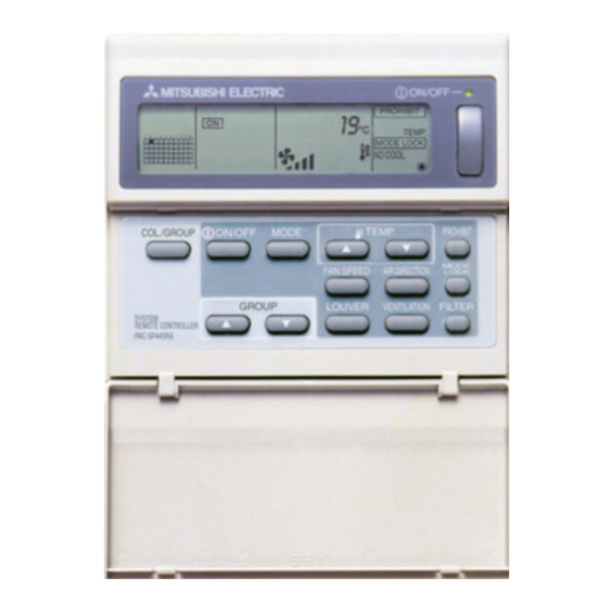
Page 4: Names And Functions Of Each Part
LOCK GROUP LOUVER VENTILATION FILTER SYSTEM REMOTE CONTROLLER PAC-SF44SRA After turning the power on,wait until the "HO"or"H1"display goes out (approximately 5 minutes) 1. COLLECTIVE/GROUP DISPLAY Indicates which mode is selected: COLLECTIVE: [Collective Setting/Monitor Screen] GROUP: [Group Setting/Monitor Screen] 2. ON/OFF DISPLAY [Collective Setting/Monitor Screen] ON display: Displays when one or more groups are running. -
Page 5: Display Sections
2-2. Display sections 1. CENTRALIZED DISPLAY This appears when operations from another system controller are prohibited. 2. ON/OFF DISPLAY The operation status of the displayed group or all groups is displayed. 3. OPERATION MODE DISPLAY The current operation mode is displayed. 4. -
Page 6: Operation Section
2-3. Operation section 1. ON/OFF SWITCH When the [Collective Setting/Monitor Screen] is displayed, all groups can be collectively started and stopped. When the [Group Setting/Monitor Screen] is displayed, the selected group can be started and stopped. 2. COL./GROUP SWITCH Press this switch to switch between the [Collective Setting/Monitor Screen] and [Group Setting/Monitor Screen]. -
Page 7: Operation
3. Operation 3-1. Collective Setting/Monitor Screen, Group Setting/Monitor Screen • [Collective Setting/Monitor Screen] • All groups controlled by this controller can be operated collectively. • When any of the following operation switches is pressed for more than two seconds, each default value will appear, and all air conditioners will be set with the next operation. -
Page 8: Various Setting Methods
3-2. Various setting methods (1) ON/OFF [Collective Setting/Monitor Screen] 1. The air conditioners and LOSSNAY for all groups will either turn ON or OFF when the ON/OFF switch is pressed. 2. Pressing the COLLECTIVE ON/OFF switch has the same effect as pressing the ON/OFF switch. - Page 9 (3) Fan speed adjustment [Collective Setting/Monitor Screen] 1. The display will change as shown on the right each time the FAN SPEED switch is pressed. 2-step model When executed collectively, the fan speed will be set in "four steps" regardless of the 3-step model model.
- Page 10 (5) LOUVER [Collective Setting/Monitor Screen, Group Setting/Monitor Screen] 1. Start/stop will be repeated each time the LOUVER switch is pressed, and the display will change as shown below. 1. When operating the louvers collectively, “LOUVER ON” will appear regardless of the model.
- Page 11 (8) Local remote controller operation prohibit setting [Collective Setting/Monitor Screen] 1. Operations with all local remote controllers controlled with this controller can be prohibited. [Group Setting/Monitor Screen] 1. Operations with the local remote controller for the selected group can be prohibited. When this controller's SW3-5 operation prohibit range setting changeover has been set to "ON (including system controller)", operations of the other system controllers can be prohibited.
- Page 12 (9) Operation mode changeover limit (season changing) Changeover to specific operation modes with this controller or the local remote controller for all groups can be limited. For example, the mode selection can be limited according to the season. Cooling mode limit (winter), heating mode limit (summer), cooling + heating mode limit (between seasons) Setting methods: Set with the [Collective Setting/Monitor screen] or [Group Setting/Monitor screen].
- Page 13 1. Selecting the setting item Select the setting item with the GROUP switches or the TEMP. switches. • Day setting : GROUP switches • Time setting : TEMP. switches 2. Setting the day (Select day setting in step 1.) The day setting No. displayed at the group No. display section will change each time the GROUP switch is pressed.
- Page 14 (11) Set temperature range limit mode If the remote control has a set temperature range limit mode function, the set temperature adjustment range can be collectively set for the [COOL/DRY] and [HEAT] modes. [Setting method and display] Use the [Collective Setting/Monitor Screen]. (Make sure that all units are stopped before starting.) Hold down the TEMP switches simultaneously for two or more seconds.
-
Page 15: Troubleshooting
• The air conditioner is stopped because a problem has occurred and operation cannot be continued. • Check the address of the unit where the error is occurring and the error code, and call your nearest MITSUBISHI ELECTRIC supplier or dealer. The group No. of the faulty unit flickers. The COLLECTIVE ON/OFF lamp flickers. -
Page 16: When An External Input Signal Is Input
1. If an error occurs while the [Collective Setting/Monitor Screen] is displayed, the details of the error for the group containing the first problem will appear. 2. If the error occurs while the [Group Setting/Monitor Screen] is displayed, the error will display only when the currently selected group has the error. -
Page 17: Initial Settings
6. Initial settings • When connecting multiple system controllers, designate the system controller with many functions as the "master", and set the system controllers with few functions as the "slaves". (Refer to section 8. Setting the functions, "8-1 Using with master system controller" for details on the "master/slave"... - Page 18 This controller's own address will flicker for two seconds. Carry out steps 6-1-1 to 6-1-2 from the state shown above. (4) Cancel the initial setting mode. • After setting the group and the interlocked unit, hold down the FILTER and LOUVER switches simultaneously for two or more seconds.
-
Page 19: Setting The Group
6-1-1. Setting the group • Register the indoor unit, LOSSNAY, slave system controller and local remote controller for each group. (Register the LOSSNAY to be interlocked with the indoor unit using the interlocked unit setting.) • If the group setting information has already been set and no operations are made on this screen for ten minutes, the display will automatically switch to the Collective Setting/Monitor screen. - Page 20 Example) When groups 1 and 2 are not registered, and the address 005 indoor unit is registered in group 3 2. Selecting the unit (1) Select the unit to be registered in the group selected in step 1. • The address No. at the set temperature display section will change in order each time the TEMP.
- Page 21 3. Registering the unit into a group (1) Register the unit selected in step 2 into a group. • With the group No. and unit address selected in steps 1 and 2 displayed, press the FAN SPEED switch. • The registration process will be completed with this step. •...
- Page 22 4. Deleting a unit from a group (1) Using steps 1 and 2, call out the address No. of the unit to be deleted. • When the FILTER switch is pressed twice in this state, the unit registered in the group will be deleted.
-
Page 23: Setting The Interlocked Units
6-1-2. Setting the interlocked units • Set that units interlocked with each group can be run in linked. • Set the interlocked units after setting the group. The interlocked units cannot be set until the units are registered in the group in which interlocked units are to be set. - Page 24 2. Selecting the group No. (1) Call the Group No. • Call the group No. in which the interlocked unit is to be registered. Use the same operations as section 6-1-1. (1) Selecting the group. • Select the group with the GROUP switches.
- Page 25 5. Registering the interlocked unit (1) When the FAN SPEED switch is pressed in the state shown in step 4, the interlocked unit will be registered as interlocked to the displayed indoor unit. • The following type of display will appear when the unit is correctly registered. The address No.
- Page 26 (2) The interlock setting will be cancelled when the FILTER switch is pressed twice in this state. The attribute display will change to "--" when completed normally. Displays alternately 7. Searching for interlocked units Search to find which indoor unit the interlocked unit is linked to. (1) To search from interlocked unit Carry out step 4 to display the address No.
-
Page 27: Collective Deletion
• If the MODE LOCK switch is pressed again in this state, the other units linked to the interlocked unit can be confirmed. Example) When the following units are linked to interlocked unit 030. Indoor unit ... 001 (group 1) 002 (group 2) The following details are searched for. -
Page 28: Error History Monitor
7. Error history monitor • Up to 50 past errors can be saved in the memory. If more than 50 errors occurred, the oldest errors will be deleted sequentially. The errors described in section '4-2 When "group operation status display" and "error code" are flickering', are not saved in the memory. -
Page 29: Using With Master System Controller
"master", and the system controllers with few functions are designated as the "slaves". The "master/slave" functions of the system controller used together are as follows. The functions have a priority in order of G50 (MJ-103MTRA) > PAC-SF44SRA > PAC-YT34STA > PAC-YT40ANRA > PAC-SC30GRA > LMAP02-E (LMAP03U). -
Page 30: Using The External Input/Output
9. Using the external input/output 9-1. External signal input function • In order to use external signal input, use the 5-wire cable for external input that comes with the unit. (1) External input By using an external no voltage contact signal, it is possible to send Emergency stop/Normal, ON/OFF or Prohibit/Permit local remote controller operation commands to all units being controlled. -
Page 31: External Signal Output Functions
(A) Level signal cases External input Operation status Emergency stop/Normal ON/OFF Contact operation Normal Emergency stop Emergency stop Normal (B) Pulse signal cases 1. Operation will start with the operation signal input, and will stop with the stop signal input. (This applies to prohibit and permit.) 2. -
Page 32: System Limits
10. System limits Master system controller and slave system controller This controller's control range Master system controller control range This controller's control range This controller's control range Unit Unit Unit When the system contains only this controller. When this controller is controlled by another system This controller is set as the master system controller. -
Page 33: Specifications
11. Specifications 11-1. Product functions • This controller can control up to 50 air conditioners and LOSSNAY. This controller has the following functions. <List of system remote controller functions> Function Details ON/OFF ON/OFF operations can be carried out collectively or for each group. The air conditioner can be set to cool, dry, fan, auto or heat Operation mode collectively or for each group. -
Page 34: Main Specifications
<List of system remote controller functions> Function Details Set the unit (indoor unit, LOSSNAY remote controller, slave system controller) Group setting group. Operation Interlocked unit setting Set interlocking with the LOSSNAY and indoor unit. Master system controller Set the system controller as the master or slave. /slave system controller (*1) Set whether to prohibit operation with the local remote controller using this Prohibit range...