Table of Contents
Advertisement
Quick Links
SERVICE MANUAL
General
Frequency control
Crystal-controlled PLL
Operation mode
FM, duplex
Operation channel
25 channels
Dial signal
Tone, 10 PPS (pulse) selectable
Supplied accessories
AC power adaptor (AC-T37), Telephone line
cords (long :2 / short : 1), Screws (4), Wall bracket
for base unit, Rechargeable battery pack
(BP-T40), Directories (2)
Handset
power source
Rechargeable battery pack BP-T40
Battery life
Standby : Approx. 30 days
Dimensions
Approx. 2
(w/h/d), antenna excluded
(Approx. 58 x 205 x 69 mm)
Antenna : 3
Mass
Approx. 10.5 oz (Approx. 300g, ) battery
inclueded
MICROFILM
SPECIFICATIONS
3
/
x 8
1
/
x 2
3
/
inches
8
8
4
1
/
inches (81 mm)
4
SPP-M100
Base unit
power source
DC 9V from AC power adaptor
Battery charging time
Apprpx. 10 hours
Dimensions
Approx. 5
3
/
x 1
3
/
x 9
1
/
inches
4
4
4
(w/h/d), antenna excluded
(Approx. 146 x 44 x 234 mm)
Antenna : 22
7
/
inches (580 mm)
8
Mass
Approx. 13.5 oz (Approx. 390g, ) battery
inclueded
Design and specifications are subject to change without notice.
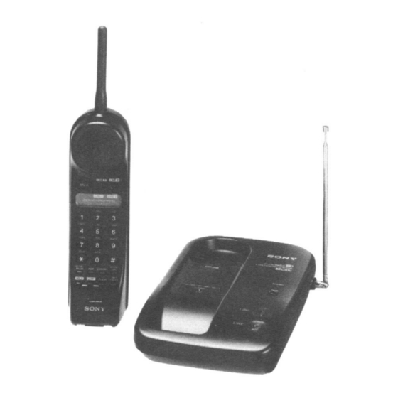
2-LINE CORDLESS TELEPHONE
E Model
Advertisement
Table of Contents

Related Manuals for Sony SPP-M100


Summary of Contents for Sony SPP-M100
- Page 1 SPP-M100 SERVICE MANUAL E Model SPECIFICATIONS Base unit General power source Frequency control DC 9V from AC power adaptor Crystal-controlled PLL Battery charging time Operation mode Apprpx. 10 hours FM, duplex Dimensions Operation channel Approx. 5 inches 25 channels (w/h/d), antenna excluded Dial signal (Approx.
-
Page 2: Table Of Contents
MARK !ON THE SCHEMATIC DIAGRAMS AND IN THE PARTS aged by heat. LIST ARE CRITICAL TO SAFE OPERATION. REPLACE THESE COMPONENTS WITH SONY PARTS WHOSE PART NUMBERS APPEAR AS SHOWN IN THIS MANUAL OR IN SUPPLEMENTS PUBLISHED BY SONY. – 2 –... -
Page 3: General
SECTION 1 GENERAL LOCATION AND FUNCTION OF CONTROLS BASE UNIT !º 1 Hang-up tab 2 LINE 2 lamp 3 LINE 1 lamp 4 PAGE button 5 CHARGE lamp 6 Telescopic antenna 7 DIAL MODE switch 8 DC IN 9V jack 9 L2 (Telephone jack) !º... - Page 4 HANDSET @º !ª !• !¶ !§ !∞ !¢ !™ !£ !¡ !º 1 SPEAKER !¡ BATT CHECK button 2 TALK button !™ Battery conmpartment 3 Battery lamps (lndicate battery level) !£ SPEED DIAL button 4 Dialing keys !¢ RING ON/BATT SAVE switch 5 REDIAL/PAUSE button !∞...
- Page 5 This section is extracted from instruction manual. – 5 –...
- Page 6 – 6 –...
- Page 7 – 7 –...
- Page 8 – 8 –...
- Page 9 – 9 –...
-
Page 10: Disassembly
SECTION 2 DISASSEMBLY Note : Follow the disassembly procedure in the numerical order given. HANDSET 2-1. COVER (BATTERY) 2-2. REAR CABINET Cover (battery) 2 Two screws (BTP 2.6X12) 1 Cover (bettery) Two claws 3 Rear cabinet Two claws 2-3. HAND MAIN BOARD 1 Screw (BTP 2.6X8) 2 Two screws... -
Page 11: Test Mode
SECTION 3 TEST MODE BASE UNIT 1. How to enter the test mode 1-1. Manual test mode [DIAL MODE] Set the switch to “P” (Pulse). [PAGE] While pressing the key, switch on the power supply. (Reset start) [PAGE] With the key still held down, switch the [DIAL MODE] switch “P”... - Page 12 1-3. Channel Setting Table • During startup in machine test mode, make the following chan- nel settings by loading the terminal input data. (Use of under- lined channels prohibited in PRISM) [PAGE] • Pressing the key in manual test mode switches one by one through the channels starting with channel 1.
- Page 13 3. Line test 4. Wireless test 3-1. L1/L2 dial test [PAGE] 4-1. key processing If the Test L1/L2 Port (IC501!ª pin) is high, L1 is connected, The channel is incremented only in manual test mode. Chan- if it is low, L2 is connected, then dial transmission is ex- nel incrementing is carried out in 25channel mode.
- Page 14 HANDSET UNIT 1. How to enter the Test Mode 1-1. Manual Test Mode [TALK] Enter the test mode by pressing key while pressing 4 and 8 when in idle condition. The RINGER will ring for 500msec when the test mode is started.
- Page 15 1-3. Channel Setting • During startup in machine test mode, make the following chan- nel settings by loading the terminal input data. [CHANNEL] • Pressing the key in manual test mode switches one by one through the channels starting with channel 1. @¶...
- Page 16 canceled. (Since WAKE UP may not be carried out be- DETECTION TIMING cause when DIP SW interferes when making key input 1. Charge detection … ) CHARGE DET Starting with key input is enabled. 9 7n : Key & LED Test. Charging [TALK] [LINE 1]...
- Page 17 3. Automatic hold release • During an outside line hold, taking the telephone set con- nected in parallel off-hook ends the outside line hold and re- leases the outside line. • Release detection 480msec PARA DET 480msec Low decided Hight decided Base unit ♣...
-
Page 18: Base Unit Test Mode Status Flow Chart
SECTION 4 BASE UNIT TEST MODE STATUS FLOW CHART Note : Manual test start procedures RESET START 1. Turn on the po wer b y holding do wn the P AGE ke y. 2. Switc h fr om P to T to P with the DIAL MODE s witc h. -
Page 19: Electrical Adjustments
SECTION 5 ELECTRICAL ADJUSTMENTS 5-1. BASE UNIT SECTION Procedure : 1 FM rf signal generator condition : • Apply 9V dc from regulated DC power supply. Carrier frequency : 48.970MHz • Set to baseunit manual test mode. (Refer to page 11.) Modulation frequency : 1kHz •... -
Page 20: Handset Section
CH1 DC 500mV/div NORMAL 5mSec/div RX Section Adjustment • Perform the adjustment at T3CH (RX : 46.800MHz) as a rule. 1. IF Adjustment Setting : FM rf signal generator DUTY of 50% TP76 (ANT) TP8 (GND) level meter DUTY is except 50% TP58 (IF) TP8 (GND) Procedure :... - Page 21 Adjustment Location : TP8 : RX VCO Adjustment TP29 : IF Adjustment TP10 : SQ SENSITIVITY Adjustment [BASE MAIN BOARD] IC303 IC304 IC305 TP401 IC306 TP402 TP10 TP29 IC301 IC501 IC201 TP12 TP17 TP9 : TX VCO Adjustment TP12 : ANT Terminal : FM rf signal generator TP17 TP401 : DET Adjustment...
-
Page 22: Diagrams
SECTION 6 DIAGRAMS 6-1. EXPLANATION OF IC TERMINALS IC501 SB662312A-4G69 (BASE UNIT CPU) Pin No. Pin name Description PLL LDA PLL LDA. H : Lock PLL DATA PLL serial data output terminal. PLL CLK PLL serial clock output terminal. RX • DATA RX data input terminal. - Page 23 IC801 SH665316A-4G70 (HANDSET CPU) Pin No. Pin name Description BEEP Beep output terminal. – Ground. OSC1 Internal oscillator. 4.048MHz. OSC2 External oscillator. 4.048MHz. – Power supply terminal (+4V). –––––– RESET Reset. L : Reset Oscillator terminal (32kHz). Oscillator terminal (32kHz). TEST –...
- Page 24 IC BLOCK DIAGRAMS IC201 LC7152M (BASE) IC301 LC7152M (HAND) 18 CB TEST PROGRAMMABLE DIVIDER-B PHASE DETECTOR (16bit) CHARGE PUMP UNLOCK DETECTOR 23 PDB2 FAST LOCK UP 22 PDB1 PROGRAMMABLE 21 AIB (14bit) REFERENCE DIVIDER 20 AOB XOUT PROGRAMMABLE DIVIDER-A PHASE DETECTOR (16bit) CHARGE PUMP UNLOCK DETECTOR...
- Page 25 WAVEFORMS 1.3Vp-p 10.2MHz IC301 @¢ 3.9Vp-p 4.048MHz IC801 2.2Vp-p 32kHz IC801...
-
Page 26: Exploded Views
SECTION 7 EXPLODED VIEWS NOTE : • -XX, -X mean standardized parts, so they • The mechanical parts with no reference The components identified by mark ! may have some difference from the original number in the exploded views are not or dotted line with mark ! are critical one. -
Page 27: Handset Section
7-2. HANDSET SECTION SP501 ANT501 BZ601 M501 Ref. No. Part No. Description Remark Ref. No. Part No. Description Remark 3-915-616-31 WINDOW 3-918-133-01 CUSHION (MICROPHONE) 3-915-615-01 BUTTON (TALK/LINE 1) 3-918-132-01 TERMINAL, BATTERY 3-914-687-91 CABINET (FRONT) (1) 3-914-699-11 TERMINAL (CHARGE), CHARGE 3-915-619-31 BUTTON (LINE 2) 3-915-621-01 HOLDER (MICROPHONE) 3-011-284-01 SPRING(B), COIL X-3369-851-1 CABINET (REAR)ASSY... -
Page 28: Electrical Parts List
SECTION 8 BASE MAIN ELECTRICAL PARTS LIST NOTE : • Due to standardization, replacements in the • SEMICONDUCTORS In each case, u : µ , for example : The components identified by mark ! parts list may be different from the parts uA.. - Page 29 BASE MAIN Ref. No. Part No. Description Remark Ref. No. Part No. Description Remark C334 1-163-009-11 CERAMIC CHIP 0.001uF C602 1-164-222-11 CERAMIC CHIP 0.22uF C335 1-163-133-00 CERAMIC CHIP 470PF C603 1-124-907-11 ELECT 10uF C336 1-163-031-11 CERAMIC CHIP 0.01uF C350 1-163-011-11 CERAMIC CHIP 0.0015uF 10% C604 1-126-941-11 ELECT...
- Page 30 BASE MAIN Ref. No. Part No. Description Remark Ref. No. Part No. Description Remark IC201 8-759-824-20 IC LC7152M Q101 8-729-031-85 TRANSISTOR 2SC4365-34-TB IC301 8-759-263-90 IC LA8637M-TLM Q103 8-729-031-86 TRANSISTOR 2SC3142-J3J4-TB IC303 8-759-030-76 IC MC34119-ML Q104 8-729-031-86 TRANSISTOR 2SC3142-J3J4-TB IC304 8-759-909-71 IC BA4558F Q105 8-729-216-22 TRANSISTOR 2SA1162-G IC305...
- Page 31 BASE MAIN Ref. No. Part No. Description Remark Ref. No. Part No. Description Remark R304 1-216-689-11 METAL CHIP 0.5% 1/10W R407 1-216-089-00 METAL GLAZE 1/10W R305 1-216-081-00 METAL CHIP 1/10W R408 1-216-113-00 METAL CHIP 470K 1/10W R308 1-216-113-00 METAL CHIP 470K 1/10W R409...
- Page 32 BASE MAIN HAND MAIN Ref. No. Part No. Description Remark Ref. No. Part No. Description Remark S502 1-572-903-21 SWITCH, SLIDE (DIAL MODE) C211 1-163-037-11 CERAMIC CHIP 0.022uF C213 1-164-161-11 CERAMIC CHIP 0.0022uF 10% 100V < TRANSFORMER > C214 1-164-161-11 CERAMIC CHIP 0.0022uF 10% 100V T401...
- Page 33 HAND MAIN Ref. No. Part No. Description Remark Ref. No. Part No. Description Remark C805 1-163-231-11 CERAMIC CHIP 15PF 1-216-295-00 METAL GLAZE 1/10W C806 1-163-117-00 CERAMIC CHIP 100PF C807 1-163-117-00 CERAMIC CHIP 100PF 1-216-296-00 METAL GLAZE 1/8W C808 1-163-117-00 CERAMIC CHIP 100PF 1-216-295-00 METAL GLAZE 1/10W...
- Page 34 HAND MAIN HAND KEY Ref. No. Part No. Description Remark Ref. No. Part No. Description Remark R209 1-216-109-00 METAL CHIP 330K 1/10W R802 1-216-057-00 METAL CHIP 2.2K 1/10W R210 1-216-049-00 METAL GLAZE 1/10W R803 1-216-057-00 METAL CHIP 2.2K 1/10W R804 1-216-057-00 METAL CHIP 2.2K 1/10W...
- Page 35 SPP-M100 Ref. No. Part No. Description Remark ANT501 1-501-703-11 ANTENNA, HELICAL ! F401 1-533-542-11 FUSE (500mA/250V) ! F451 1-533-542-11 FUSE (500mA/250V) M501 1-542-161-11 MICROPHONE, ELECTRET CONDENSER SP501 1-504-261-21 SPEAKER (2.8cm) ************************************************************ ACCESSORIES & PACKING MATERIALS ******************************** 1-467-498-21 ADAPTOR, AC (AC-T47)