Table of Contents
Advertisement
Available languages
Available languages
Use & Care Guide
Manual de Uso y Cuidado
English / Español
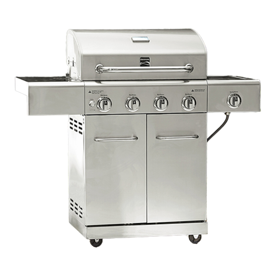
Kenmore
Liquid Propane Gas Grill
Parilla a gas de propane liquido
Model/Modélo:
Item/Artículo:
P/N 19000432A0
Hoffman Estates, IL 60179 U.S.A
www.kenmore.com
www.sears.com
www.kmart.com
®
®
– Stainless Steel / Acero Inoxidoble
122.33492410
– Stainless Steel / Acero Inoxidoble
640-05861277-1
Advertisement
Table of Contents

Related Manuals for Kenmore 122.33492410


Summary of Contents for Kenmore 122.33492410
- Page 1 English / Español Kenmore ® Liquid Propane Gas Grill Parilla a gas de propane liquido Model/Modélo: – Stainless Steel / Acero Inoxidoble 122.33492410 Item/Artículo: – Stainless Steel / Acero Inoxidoble 640-05861277-1 P/N 19000432A0 Sears Brands Management Corporation Hoffman Estates, IL 60179 U.S.A www.kenmore.com...
-
Page 2: Table Of Contents
Congratulations on making a smart purchase. Your new 1.Expendable items that can wear out from normal use within the warranty Kenmore product is designed and manufactured for years of period, including but not limited to batteries, light bulbs and surface dependable operation. - Page 3 Precautions A tank of approximately 12 inches in diameter by 18-1/2 inches high is the maximum size LP gas tank to use. WARNING Failure to comply with these instructions could result in a You must use an OPD gas tank which offers an Overfill fire or explosion that could cause serious bodily injury, Prevention Device.
- Page 4 WARNING • Have your LP gas tank filled by a reputable propane A strong gas smell, or the hissing sound of gas gas dealer and visually inspected and re-qualified at indicates a serious problem with your gas grill or the each filling.
- Page 5 CAUTION: Beware of Flash-Back Burner Flame Check CAUTION: Spiders and small insects occasionally spin webs or make nests in the grill burner tubes during transit and warehousing. These webs can lead to gas flow obstruction which could result in a fire in and around burner tubes.
-
Page 6: Lighting Instructions
Grill Lighting Instruction USING THE SIDE BURNER: Inspect the gas supply hose prior to turning the gas Grill Lighting Instructions for Main Burners “ON”. If there is evidence of cuts, wear or abrasion, it 1. Do not smoke while lighting grill or checking gas supply must be replaced prior to use. - Page 7 WARNING If Grill Still Fails To Light Never lean over the grill cooking area while lighting 1. Check gas supply and connections for leaks. Check that your gas grill. Keep your face and body a safe all wire connections are secure. distance (at least 18 inches) from the cooking grid surface when lighting your grill by match.
-
Page 8: Package Content List
Package Contents List A. Grill Head-1PC B. Main lid handle-1PC C. Handle bezel -2PCS D. Side shelf -1PC E. Sear burner with side shelf front F. Grease tray-1PC panel-1PC G. Grease cup-1PC H. Back panel, bottom -1PC I. Side panel, right-1PC J. - Page 9 P. Triangle bracket, right -1PC Q. Swivel caster -2PCS R. Swivel caster with brake -2PCS S. Door handle -2PCS T. Door, left-1PC U. Door, right -1PC W. Sear burner cooking grid-1PC X. Flame tamer-4PCS V. Sear burner grease tray-1PC Y. Cooking grid w/hole-2PCS Z.
-
Page 10: Preparation
Hardware Pack Contents Item Description Specification Quantity Screw with Lock Washer 1/4'' x 15mm 18pcs Screw 1/4'' x 15mm 31pcs / " Screw 5/32'' x 10mm 8pcs Flat Washer 5/32'' 4pcs Flat Washer 1/4" 20pcs Screw 1/4'' x 8mm 2pcs / "... - Page 11 Exploded View...
-
Page 12: Parts List
Parts List Part No. PART (Description) Warranty Part No. PART (Description) Warranty 0830A-036 Sear Burner Lid Hinge 0830A-001 Main Lid Rod Pin 0830A-037 Sear Burner Bowl 0830A-002 Main Lid Screw Assembly 0830A-003 Main Lid Handle 0830A-038 Sear Burner Grease Tray 0830A-004 Temperature Gauge 0830A-039... -
Page 13: Assembly Instructions
3. Part Number (see PART# in chart) To make sure you obtain the correct replacement parts for 4. Part Description your Kenmore gas grill, please refer to the part numbers in 5. Quantity of parts needed the part list. Assembly Instructions... - Page 14 2. Side Panel and Back Panel Attach left & right side panels to bottom panel using six ¼”x 15mm screws (BB). Attach back panel to bottom panel using seven ¼”x 15mm screws (BB). 3. Door Triangle Bracket and Cart Beam Loosen but do not remove the four screws on the left side panel and bottom panel.
- Page 15 4. Grease Tray and Door Handle Attach the grease cup brackets to the grease tray by using four 5/32” x 10mm screws (CC). and four 5/32” flat washers(DD). Attach a door handle to each door using two 1/4" x 15 mm screws (BB).
- Page 16 6. Grill Head Placement With the aid of an assistant, carefully place the grill head onto the grill cart. Attach grill head to left and right side panels using two 1/4" x 15 mm screws (BB) for each side. 7. Door assembly Insert the bottom hinge pin of left door into the hole in the bottom panel.
- Page 17 8. Searing Side Burner Shelf Assembly a. Remove grate from searing side burner shelf and set aside. Open Grill Head Lid. Loosen but do not remove the two screws on the outside surface of the Grill Head. Place the slotted holes on searing side burner shelf over the two screw heads and drop down.
- Page 18 d. Loosen but not remove the 2 screws that are pre- attached to the side burner gas valve. Insert the valve stem and two screws through the corresponding holes in the control panel. Align the screws on the valve with the large side of the holes on the bezel and slide the screws down to smaller holes and tighten the screws to secure.
- Page 19 9. Side shelf and lid handle assembly a. Open Grill Head Lid. Loosen but do not remove the two screws on the outside surface of the Grill Head. Place the slotted holes on side shelf over the two screw heads and drop down. Do not tighten screws until end of next step.
- Page 20 11. Battery and Liquid Propane Tank Installation Unscrew the electronic ignition button and place the battery into the compartment with the positive terminal (+) facing outward. Replace the ignition button after the battery has been installed. From the front of cart, place LP Tank into the hole in bottom panel.
- Page 21 Congratulations tighten the coupling nut, holding regulator in a straight line with Your Kenmore gas grill is now ready for use. Before LP tank valve so as not to crossthread the connection. the first use and at the beginning of each season (and whenever the LP gas tank has been changed): 1.
-
Page 22: Natural Gas Conversion
Natural Gas Conversion for Model# 122.33492410 Use NG Conversion Kit Part No.710-0778A, available by calling 1-800-4-MY-HOME. WARNING! FALURE TO HEED THESE WARNINGS COULD RESULT IN A FIRE OR EXPLOSION THAT COULD CAUSE SERIOUS BODILY INJURY, DEATH OR PROPERTY DAMAGE. Installation of this Natural Gas Conversion kit must be performed by a QUALIFIED GAS TECHNICIAN ONLY. DO NOT ATTEMPT TO INSTALL THIS KIT YOURSELF. - Page 23 Natural Gas Conversion for Model# 122.33492410 Warning: Make sure all grill components are completely cooled down and gas supply is turned off and removed from grill prior to performing the conversion. NG Hose and Regulator Conversion Tools required: Phillips Head Screwdriver (+) 14mm wrench Turn all knobs OFF.
- Page 24 Natural Gas Conversion for Model# 122.33492410 Main Tube Burner Conversion Tools required: Phillips Head Screwdriver (+) Needle nose pliers 6 mm Nut Driver Steps: Remove the warming rack, cooking grids, and flame tamers. Remove the main tube burners by removing the pin securing the burners near the back wall of the firebox.
- Page 25 Natural Gas Conversion for Model# 122.33492410 For Main Tube Burner Conversion Only (The 3 steps below are not necessary for the searing side burner ) You will need to adjust the High Flame setting screw when converting the barbecue from Propane to Natural Gas.
- Page 26 Natural Gas Conversion for Model# 122.33492410 Searing Side Burner Conversion Tools required: Phillips Head Screwdriver (+) 6mm Wrench Steps: 1. Close main lid and remove the three screws which are pre-assembled to the Igniter electrode wire and searing side burner.
-
Page 27: Cooking Instruction
Cooking Instructions Indirect Cooking To cook indirectly, the food should be placed on the left or right side of your grill with the burner lit on the WARNING opposite side. Do not leave the grill unattended. Your grill will get very hot. Never lean over the Flare-ups cooking area while using your grill. -
Page 28: Cooking Chart
Grill Cooking Chart FOOD Weight or thickness Temperature Time Special instructions and tips Slice or chop vegetables and dot with butter or Vegetables Medium 8 to 20 minutes margarine. Wrap tightly in heavy duty foil. Grill turning occassionally. Wrap individually in heavy duty foil. Cook Potatoes Whole Medium... -
Page 29: Cleaning And Maintenance
Cleaning and Maintenance Cleaning Exterior Stainless Steel Surfaces Weathering and extreme heat can cause exterior stainless steel To ensure a proper working unit the following proper care surfaces to turn tan in color. Machine oils used in manufacturing and maintenance is suggested. process of stainless steel can also cause this tanning color. -
Page 30: Troubleshooting
WARNING 2. Clean any clogged ports with a stiff wire, such as an open The location of the burner tube with respect to the orifice is vital paper clip. for safe operation. Check to ensure the orifice is inside the 3. -
Page 31: Sears Brands Management Corporation
Esta garantía SOLO cubre defectos en materiales producto Kenmore está diseñado y fabricado para que disfrute de y mano de obra. Sears NO PAGARÁ por: años de uso digno de confianza. Pero como todos los productos, es 1. - Page 32 Precauciones Un tanque de 12 pulgadas de diámetro por 18½ pulgadas de alto aproximadamente es el tamaño máximo del tanque de gas LP para usar en la prrilla. ADVERTENCIA Debe usar un tanque de gas OPD que brinda un Dispositivo En caso de que estas instrucciones no se cumplieran, ello podría dar como resultado un incendio o una explosión de Prevención por Sobrecarga.
- Page 33 • Los tanques de gas LP deben guardarse en exteriores, en áreas bien ventiladas y fuera del alcance de los niños. •No obstruya el flujo de aire de la ventilación que se encuentra en la No deben guardarse los tanques de gas LP desconectados en carcasa de la parrilla de gas.
- Page 34 NOTA: El flujo normal de gas que va por el ensamble del Control de las llamas de los mecheros regulador y la manguera puede causar un zumbido. Un volumen bajo de ruido es perfectamente normal y no interferirá con la operación de la parrilla.
- Page 35 Verificación para detectar fugas de gas LP Instrucciones de encendido de la parrilla Nunca haga pruebas para detectar fugas con una llama. Antes de usarla por primera vez, al comienzo de cada estación o cada vez que se cambie el tanque de gas LP, debe verificar el dispositivo Instrucciones de encendido para los mecheros principales para detectar fugas de gas.
- Page 36 USO DEL MECHERO LATERAL: Encendido manual de la parrilla con un cerillo Inspeccione la manguera del suministro de gas antes de abrir 1. Coloque un cerillo en la varilla de encendido manual. el paso del gas (ON). Si hubiera evidencias de cortes, desgaste o abrasión, debe reemplazarla antes de usar la 2.
- Page 37 Si no se puede encender la parrilla 5. Si se han realizado todas las operaciones de verificación y 1. Verifique el suministro y las conexiones de gas para detectar corrección y aún tiene consultas sobre la operación de su parrilla fugas.
- Page 38 LISTADO DEL CONTENIDO DEL PAQUETE A. Cabezal de la parrilla ---1 B. Mango de la tapa principal—1 C. Asiento del mango—2 pieza pieza piezas D. Estante lateral—1 pieza E. Mechero de marcado con F. Bandeja para grasa---1 pieza estante lateral del panel delantero—1 pieza G.
- Page 39 P. Abrazadera triangular, Q. Rueda giratoria --- 2 piezas R. Rueda giratoria con freno derecha---1 pieza --- 2 piezas S. Mango de la puerta —2 piezas T. Puerta, lado derecho -- 1 pieza U. Puerta, lado izquierdo --- 1 pieza X.
- Page 40 Contenidos del equipo Especificación Cantidad Descripción Artículo Tornillo de cabeza ovalada 1/4'' x 15mm 18piezas Tornillo 1/4'' x 15mm 31piezas Tornillos 5/32'' x 10mm 8piezas Arandela plana 5/32'' 4piezas Arandela plana 1/4" 20piezas Tornillos 1/4" x 8mm 2piezas / " Preparación Antes de comenzar el armado, asegúrese de tener todas las piezas.
- Page 41 Diagrama de las piezas del Modelo 122.16134110...
- Page 42 Listado de las piezas del Modelo 122.16134110 Cobertura Cobertura por garantía Cant. garantía PIEZA (Descripción) Part No. (Anual) PIEZA (Descripción) Part No. (Anual) Cant. Varilla de la bisagra de la tapa del mechero de marcado 0830A-035 Tapa principal 0830A-001 Pasador de barra de la bisagra de la tapa del mechero de 0830A-036 Tornillo de la tapa principal 0830A-002...
- Page 43 Para solicitar partes de repuestos luego de usar la parrilla, llame a: 1-800-4-MY-HOME® Para asegurarse de que le entregan las piezas de reemplazo correctas para su parrilla de gas Kenmore, consulte los números de pieza en esta página. Importante: Use únicamente las piezas detalladas con anterioridad. Al solicitar piezas, brinde la siguiente información: 1.
- Page 44 2. Panel lateral y panel trasero Fije los paneles laterales izquierdo y derecho al panel inferior utilizando seis tornillos (BB) de ¼" x 15 mm. Fije el panel trasero al panel inferior utilizando siete tornillos (BB) de ¼” x 15 mm. 3.
- Page 45 5. Bandeja para grasa y caja para grasa Instale la bandeja para grasa en el carro con cuatro tornillos de 5/32" x 10 mm (CC). Instale el recipiente para grasa bajo la bandeja para grasa. 6. Colocación del cabezal de la parrilla Con la ayuda de un asistente coloque cuidadosamente el cabezal en el carro del asador.
- Page 46 8. Ensamble del estante del mechero lateral para marcado a. Quite la rejilla del estante del mechero lateral y déjela aparte. Abra la tapa del cabezal de la parrilla. Afloje sin retirar los dos tornillos de la superficie exterior del cabezal. Alinee los agujeros ranurados de la repisa del mechero lateral para marcado con la cabeza de los dos tornillos y deje caer la repisa.
- Page 47 d. Afloje pero no quite los 2 tornillos que ya vienen atornillados en la válvula de gas del mechero lateral.. Inserte el vástago de la válvula y los dos tornillos a través de los agujeros correspondientes del panel de control. Alinee los tornillos de la válvula con el lado grande de los orificios del bisel y deslice los tornillos hacia abajo dentro de los orificios pequeños y apriételos para fijarlos.
- Page 48 9. Armado de los estantes laterales y del mango de la tapa a. Abra la tapa del cabezal de la parrilla. Afloje sin retirar los dos tornillos de la superficie exterior del cabezal. Alinee los agujeros ranurados de la repisa lateral con la cabeza de los dos tornillos y deje caer la repisa.
- Page 49 11. Instalación de la batería y del tanque de propano líquido Destornille el botón de encendido eléctrico y coloque la batería en el hueco con el extremo positivo (+) hacia afuera. Vuelva a colocar el botón de encendido luego de que la batería se haya instalado.
- Page 50 5. Sostenga el regulador e inserte el empalme en la válvula del Felicitaciones Su parrilla de gas Kenmore ya está lista para usarse. tanque LP. Apriete con la mano la tuerca del acoplador, Antes de usarla por primera vez y al principio de cada sosteniendo el regular verticalmente con respecto del tanque estación (y siempre que se haya cambiado el tanque de...
- Page 51 Conversión a gas natural para el Modelo N°122.33492410 Utilice Conversión de gas natural Parte No.710-0778A, disponible llamando al 1-800-4-MY-HOME. ¡ADVERTENCIA! SI HACE CASO OMISO DE ESTAS ADVERTENCIAS, ELLO PODRÍA DAR COMO RESULTADO UN INCENDIO O UNA EXPLOSIÓN QUE PODRÍA CAUSAR LESIONES CORPORALES GRAVES, LA MUERTE O DAÑOS A LA PROPIEDAD.
- Page 52 Conversión a gas natural para el Modelo N°122.33492410 Advertencia: Asegúrese de que todos los componentes de la parrilla estén totalmente fríos y que el suministro de gas esté cerrado y alejado de la parrilla antes de realizar la conversión. Conversión de la manguera y el regulador a...
- Page 53 Conversión a gas natural para el Modelo N°122.33492410 Conversión del mechero del tubo principal Herramientas necesarias: Destornillador tipo Phillps (+) Pinza alicate Botaperno de 6 mm Pasos: Retire la plataforma de calentamiento, las rejillas de cocción y los domadores de llamas.
- Page 54 Conversión a gas natural para el Modelo N°122.33492410 Únicamente para la conversión del mechero del tubo principal (Los 3 pasos no son necesarios para el mechero de marcado) Será necesario ajustar el tornillo de ajuste de la llama tras convertir la parrilla de propano a gas natural.
- Page 55 Conversión a gas natural para el Modelo N°122.33492410 Conversión del mechero lateral para marcado Herramientas necesarias: Destornillador tipo Phillps (+) Botaperno de 6 mm Conversión del mechero lateral para marcado: 1. Cierre la tapa principal y quite los tres tornillos que vienen pre-ensamblados en el cable del encendedor y en el mechero lateral para marcado.
- Page 56 ADVERTENCIA Instrucciones de cocción No cubra la parte posterior de la carcasa de la parrilla con láminas de aluminio, arena o cualquier otra sustancia que limite el paso del flujo de grasa hacia la ADVERTENCIA bandeja para grasa. No deje la parrilla sin prestarle atención. Su parrilla En caso de que estas instrucciones no se cumplieran, llegará...
- Page 57 Tabla de cocción en la parrilla ADVERTENCIA: Para asegurarse de que lo que se prepara para comer no conlleve riesgos, los alimentos deben cocinarse a un mínimo de temperatura interna que se detalla en la tabla siguiente. Temperaturas seguras mínimas de cocción interna de la USDA* 62,78 °...
- Page 58 Limpieza y Mantenimiento 6. Limpie con un cepillo de nylon el interior y la parte posterior de la Para asegurarse de que la unidad funcione correctamente, se sugiere que se lleven a cabo las siguientes pautas de cuidado y parrilla y lávelos con una solución hecha con jabón suave y agua tibia.
- Page 59 Independientemente de qué procedimiento de limpieza emplee, le recomendamos también realizar los siguientes pasos para Paso 1. Reemplazar clip de R. ayudar a prolongar la utilidad del mechero. Paso 2. Quite el clip R que fija el mechero en el lateral del extremo. Paso 3.
- Page 60 Localización y resolución de problemas ANTES DE LLAMAR AL SERVICIO Si la parrilla no funciona adecuadamente, emplee la siguiente lista de verificación antes de llamar para solicitar servicios. Debe inspeccionar los mecheros una vez al año o inmediatamente después de que ocurra cualquiera de las siguientes situaciones : PROBLEMAS QUÉ...
-
Page 61: Owner's Manual
Get it fixed, at your home or ours! Your Home For troubleshooting, product manuals and expert advice: www.managemylife.com For repair – in your home – of all major brand appliances, lawn and garden equipment, or heating and cooling systems, no matter who made it, no matter who sold it! For the replacement parts, accessories and owner’s manuals that you need to do-it-yourself.