Sony HVL-F60M Operating Instructions Manual
Flash
Hide thumbs
Also See for HVL-F60M:
- Operating instructions manual (209 pages) ,
- Service manual (32 pages)
Table of Contents
Advertisement
Quick Links
Advertisement
Table of Contents

Related Manuals for Sony HVL-F60M


Summary of Contents for Sony HVL-F60M
- Page 1 4-444-194-11(1) Flash Operating Instructions Mode d’emploi HVL-F60M...
-
Page 2: Important Safety Instructions
English Before operating the product, please read this manual thoroughly and retain it for future reference. WARNING To reduce fire or shock hazard, do not expose the unit to rain or moisture. Do not expose the batteries to excessive heat such as sunshine, fire or the like. Tape over lithium battery contacts to avoid short-circuit when disposing of batteries, and follow local regulations for battery disposal. - Page 3 Care must be taken as burns can occur from touching hot parts. Do not operate appliance with a damaged cord or if the appliance has been dropped or damaged- until it has been examined by a qualified serviceman. Let appliance cool completely before putting away. Loop cord loosely around appliance when storing.
- Page 4 Notice for the customers in the countries applying EU Directives The manufacturer of this product is Sony Corporation, 1-7-1 Konan Minato-ku Tokyo, 108-0075 Japan. The Authorized Representative for EMC and product safety is Sony Deutschland GmbH, Hedelfinger Strasse 61, 70327 Stuttgart, Germany.
- Page 5 NOTE: This equipment has been tested and found to comply with the limits for a Class B digital device, pursuant to Part 15 of the FCC Rules. These limits are designed to provide reasonable protection against harmful interference in a residential installation.
-
Page 6: Table Of Contents
Table of Contents Features ....................9 Name of parts ..................10 Preparations Inserting batteries .................. 19 Attachment and removal of the flash unit ..........20 Storing this flash unit ................23 Turning on the power ................24 Changing the flash mode ............... 27 Basics AUTO flash (The basics) ............... - Page 7 MENU settings ..................88 Additional Information Notes on use ..................98 Maintenance ..................100 Specifications ..................101...
- Page 8 Recorders that have an Auto-lock Accessory Shoe. Some functions may not work depending on the model of your camera or video camera recorder. For details on compatible camera models of this flash unit, visit the Sony website in your area, or consult your Sony dealer or local authorized Sony service facility.
-
Page 9: Features
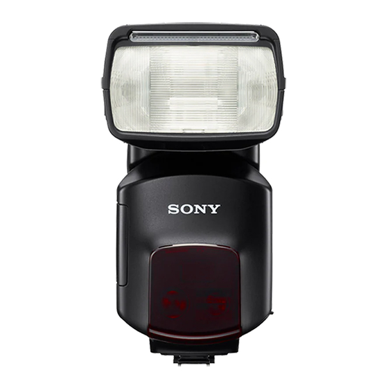
Features The HVL-F60M is a functional, clip-on flash that provides a page 101 large flash output with a guide number of 60 (105 mm position, ISO 100 · m). Quick shift bounce function enables page 50 you to set the upper or side position easily during bounce flash photography. -
Page 10: Name Of Parts
Name of parts A Built-in wide panel (for flash) E Terminal cap (84, 86) (44) F Multi Interface foot (20) B Flashtube G Built-in bounce sheet (for flash) C Wireless control signal receiver (50) (68) H Built-in diffuser (for LED light) D AF illuminator (87) (38) I LIGHT button (36) - Page 11 K Vertical bounce angle indicator R Color conversion filter (for LED (48) light) (38) L LCD panel (13) S Mini-stand (66) M Control panel (12) * Tripod mount T Connector protect cap (20) N Lock lever (20) U Shoe Adaptor (22) O Battery-chamber door (19) P Bounce indicator (side angle) (48)
-
Page 12: Control Panel
Control panel MENU LEVEL A Fn (function) button (15, 17) D Control wheel (17) B MODE button (27) E MENU button (88) C TEST button (40) F LCD illuminator button The status while the lamp is lit G Power switch (24) Amber: Flash ready Green: Proper exposure LCD panel illuminator... -
Page 13: Manual Flash
Normal indicator screen The details displayed change depending on the flash mode selected with the MODE button. • For the method of changing the flash mode, see page 27. • The screen here is just an example. The indicators shown vary depending on the situation. - Page 14 Multiple flash (MULTI mode) Wireless remote Wireless control (WL RMT mode) (WL CTRL mode) M Multiple-flash frequency P Beep indicator (92) indicator (59) Q Wireless remote setting N Multiple-flash repetition indicator (71) indicator (59) R Wireless control setting O Wireless channel indicator (91) indicator (75, 79) S Ratio-flash indicator (75) Figures in parentheses are the page...
- Page 15 Quick Navi screen and dedicated setting screen To change the settings, press the Fn button on the normal indicator screen to switch to the settings screen. MODE screen (27) Normal indicator screen MENU screen (89) Quick Navi screen Dedicated settings screen Rotate to change the setting value : Press the center...
- Page 16 Quick Navi screen Press the Fn button on the normal indicator screen to switch to the Quick Navi screen. On the Quick Navi screen, use the cursor to select the item to be set. The selected item is highlighted. The settings of the main indicators shown on the normal indicator screen such as the zoom indicator and the flash compensation indicator can be changed in the same way as on the normal indicator screen.
- Page 17 Using the control wheel With this flash unit, you can use the control wheel to operate according to the displayed screen. • Normal indicator screen Commonly used settings are allocated to different directions of the control wheel. Pressing either direction of the control wheel switches to the dedicated settings screen for different setting items.
- Page 18 • Other screens Operation varies according to the screen displayed. – MENU screen (page 89) – MODE screen (page 27) – Dedicated settings screen (page 16)
-
Page 19: Preparations
Preparations Inserting batteries The HVL-F60M may be powered by : • Four AA-size alkaline batteries* • Four AA-size rechargeable nickel-metal hydride (Ni-MH) batteries* * Batteries are not supplied. Always ensure that rechargeable nickel-metal hydride batteries are charged in the specified charger unit. -
Page 20: Attachment And Removal Of The Flash Unit
Attachment and removal of the flash unit Attaching the flash unit to the camera • Before attaching to the camera, remove the protective cap from the terminal of the Multi Interface foot of the flash unit and remove the shoe cap from the camera. •... -
Page 21: Removing The Flash Unit From The Camera
Removing the flash unit from the camera While pressing the button on the end of the lock lever 1, move the lever towards [RELEASE] 2. With the lever in the [RELEASE] position, slide the flash unit forward. - Page 22 Shoe Adaptor(ADP-AMA) When attaching this flash unit to a camera that has an Auto-lock Accessory Shoe, use the supplied Shoe Adaptor (ADP-AMA). Multi Interface Shoe Release button Attach the Shoe Adaptor as illustrated. • Slide it on firmly until it clicks into place.
-
Page 23: Storing This Flash Unit
Storing this flash unit You can store this flash unit and supplied items into the supplied cases and pouch as illustrated below. -
Page 24: Turning On The Power
Turning on the power Set the power switch to ON. The power of the flash unit turns on. • The normal indicator screen is displayed on the LCD panel when the power is turned on. • If nothing appears on the LCD panel when the power switch is set to ON, check the orientation of the batteries. -
Page 25: Power Save Mode
Power save mode If the flash unit is not operated for three minutes while disconnected from a camera or while connected to a camera in power save mode, the flash unit automatically turns off and the LCD panel goes off in order to save power. •... - Page 26 • Depending on the conditions of use or the age of the batteries, the battery dead screen may appear without the low battery indicator being shown. • Even if the low battery indicator appears, it may disappear when you change from flash to LED light or vice versa.
-
Page 27: Changing The Flash Mode
Changing the flash mode Press the MODE button to display the MODE screen. Move the cursor (highlighted item) by rotating the control wheel or pressing it up, down, left or right to select a flash mode. Set the selected mode by pressing the center of the control wheel or the MODE button. - Page 28 • Depending on the camera's flash mode, you may be unable to select a flash mode even if it is not shown by a dotted line, and the screen may not change to the normal indicator screen before the flash mode was changed. •...
- Page 29 Selectable modes Mode Description [TTL] Metering uses information from the camera Flash unit does not fire (Flash off) [MANUAL] Metering uses the settings on the flash unit Flash unit is triggered a number of times while the [MULTI] shutter is open (multiple flash) Flash unit is triggered wirelessly as an off-camera [WL RMT] (remote) flash...
-
Page 30: Basics
Basics AUTO flash (The basics) • If your camera has an automatic flash mode such as Scene Selection or AUTO Advance, it is dealt with here as AUTO. Select the AUTO mode on the camera. Press the MODE button to display the MODE screen and select [TTL]. - Page 31 When the flash unit is charged, press the shutter button to take a photo. • The flash unit is fully charged when the TEST button on the control panel is lit in amber. When the correct exposure has been obtained for the photo just taken, the TEST button on the control panel blinks in green.
-
Page 32: Flash Range
Flash range Press the shutter button halfway down. The flash range for the proper exposure is displayed on the LCD panel. Make sure that the subject is within this range and then take the photo. The range that can be displayed on the LCD panel is from 1.0 m to 28 m (0.7 m to 28 m for downward bounce;... - Page 33 Auto WB Adjustment with Color Temperature Info White balance is automatically adjusted by your camera (except the DSLR-A100) based on color temperature information when the flash unit fires. • This function works with TTL flash mode using the clip-on connection with the camera.
-
Page 34: Using Flash In Each Recording Mode Of The Camera
Using flash in each recording mode of the camera If the camera is set to aperture priority (A mode), shutter speed priority (S mode) or manual exposure mode (M mode), TTL flash photography can be performed according to the mode. Set the camera’s recording mode. - Page 35 Press the shutter button when charging is complete. TTL flash Manual flash provides a fixed flash intensity irrespective of the brightness of the subject and the camera setting. TTL* flash measures the light from the subject that is reflected through the lens. TTL metering also has a P-TTL metering function, which adds a pre-flash to TTL metering, and an ADI metering function, which adds distance data to the P-TTL metering.
-
Page 36: Shooting With Illumination (Led Light)
Shooting with illumination (LED light) Using the LED light as an illuminator lets you create natural light and shadows and shoot realistic movies even in poor light such as indoors. Using the light Make the flash unit vertical (90° upward bounce) Press the LIGHT button next to the LED light until it comes on. - Page 37 Change the brightness with the control wheel. • You can rotate the control wheel or press it up or down to adjust the brightness of the light to 15 levels. • The brightness level is shown on the LIGHT screen. •...
-
Page 38: Adjusting The Illuminating Light (Led Light) (Built-In Diffuser, Color Conversion Filter)
Adjusting the illuminating light (LED light) (built-in diffuser, color conversion filter) Using a built-in diffuser reduces glare and softens light. It can also lessen unnatural multiple shadows. Using a color conversion filter lets you change the color temperature to about 3,200K (at maximum brightness). - Page 39 • The color conversion filter can be used whether the built-in diffuser is fitted or not. • When using a filter, the illuminance is slightly reduced and the illuminating angle is a little narrower. • The color conversion filter can be fitted irrespective of its horizontal orientation.
-
Page 40: Advanced Operations
Advanced Operations Test-flash You can try a test flash before shooting. Check the light level using the test flash when you use a flash meter, etc., in the manual flash (M) mode. Press the TEST button when the TEST button lights up in amber. -
Page 41: Zoom Flash Coverage
Zoom flash coverage Auto zoom This flash unit automatically switches optimum flash coverage (zoom flash coverage) to cover a range of focal lengths from 24 mm to 105 mm when photographing (auto zoom). Normally, you do not need to switch the flash coverage manually. - Page 42 Manual zoom You can manually set the flash coverage regardless of the focal length of the lens in use (manual zoom). Press the control wheel up (ZOOM). Rotate the control wheel or press it up or down to select a setting value, and press the center of the control wheel to set that value.
- Page 43 Flash coverage & focal length The larger the focal length figure of the lens on a camera, the further away a subject can be photographed to take up the full screen; but the area that can be covered becomes smaller. Conversely, with a smaller focal length figure, subjects can be photographed with wider coverage.
- Page 44 Built-in wide panel (for flash) (15 mm zoom angle) Pulling out the built-in wide panel expands flash coverage to a 15mm focal length. Pull out the wide panel and set it at the front of flash tube, and then push back the bounce sheet. •...
-
Page 45: Flash Compensation
Flash compensation When the flash unit is in a flash mode that supports TTL metering, the flash intensity is automatically adjusted. However, you can correct this automatically adjusted flash intensity. • Flash modes that support TTL metering – TTL mode –... - Page 46 Rotate the control wheel or press it left or right to select a setting value, and press the center of the control wheel to set that value. • Setting values: -3.0, -2.5, -2.0~ ±0.0~ +2.0, +2.5, +3.0 (steps of 0.5) -3.0, -2.7, -2.3, -2.0~±0.0~+2.0, +2.3, +2.7, +3.0 (steps of 0.3) •...
-
Page 47: Bounce Flash
Bounce flash Using the flash unit with a wall directly behind the subject produces strong shadows on the wall. By directing the flash unit at the ceiling you can illuminate the subject with reflected light, reducing the intensity of the shadows and producing a softer light on the screen. - Page 48 Rotate the flash unit upwards or to the left and right while holding the camera firmly. The bounce indicator at the top right of the screen changes depending on the bounce status of the flash unit. : No bounce : Sideways bounce only : Upward bounce or sideways + upward bounce : Downward bounce or sideways + downward bounce •...
- Page 49 Adjusting bounce angle Simultaneously using direct light and bounced light from the flash unit produces uneven lighting. Determine the bounce angle with respect to the distance to the reflective surface, the distance from the camera to the subject, the focal length of the lens, etc.
- Page 50 When the flash is bounced upwards Determine the angle in relation to the following table. Focal length of lens Bounce angle 70 mm minimum 30°, 45° 28 mm - 70 mm 60° 28 mm maximum 75°, 90° Using the bounce sheet (for flash) The bounce sheet creates a highlight in the subject's eyes and makes the subject look more vibrant.
- Page 51 90° sideways bounce When the bounce angle is set to while shooting in the 90° sideways and 0° upwards portrait position, the top and bottom of the photo may darken. In this case, use the built-in wide panel or set the bounce angle to 0°...
-
Page 52: Using The Bounce Adaptor
Using the bounce adaptor Fitting the supplied bounce adaptor lets you diffuse the light from the flash over a wider range, producing a softer light and reducing shadows. Attaching the bounce adaptor Fit the bounce adaptor in the direction of the arrow in illustration, aligning the clips on the bounce adaptor with the grooves in the flash unit. - Page 53 • When fitting the bounce adaptor, [BOUNCE ADAPTOR] is shown in the zoom indicator. (When using the built-in wide panel, [WIDE] is also shown.) • The zoom position is locked. Removing the bounce adaptor While pulling the bounce adaptor handle in the direction of arrow 1, remove the bounce adaptor in the direction of arrow 2.
-
Page 54: Close-Up Photography (Downward Bounce)
Close-up photography (downward bounce) Tilt the flash slightly downwards for flash photography when the object is between 0.7 m and 1.0 m from the camera to ensure accurate illumination. Rotate the flash downwards with holding the camera firmly. • The rotation angle is 10°. •... -
Page 55: Manual Flash (M)
Manual flash (M) Normal TTL flash metering automatically adjusts the flash intensity to provide the proper exposure for the subject. Manual flash provides a fixed flash intensity irrespective of the brightness of the subject and the camera setting. • As manual flash is not affected by the reflectivity of the subject, it is convenient for use with subjects with extremely high or low reflectivity. - Page 56 Rotate the control wheel or press it left or right to select a setting value, and press the center of the control wheel to set that value. • Setting values: 1/1, 1/2, 1/4, 1/8, 1/16, 1/32, 1/64, 1/128, 1/256 (Size of setting steps = 0.5 or 0.3) •...
- Page 57 • When the shutter button is pressed halfway down, the distance at which the proper exposure is obtained appears on the LCD panel. Set the aperture to match the displayed distance to the shooting distance. Proper exposure is obtained at less than 1.0 m. If the flash range is less than 1.0 m, the lower area of the image on the LCD monitor of the camera may become dark.
-
Page 58: High-Speed Sync (Hss)
For details on setting the HSS features, see “MENU settings” (page 88). • HSS may not work depending on the camera model used. For details on compatible camera models of this flash unit, visit the Sony website in your area, or consult your Sony dealer or local authorized Sony service facility. -
Page 59: Multiple Flash (Multi)
Multiple flash (MULTI) The flash is triggered a number of times while the shutter is open (multiple flash). Multiple flash allows motion of the subject to be captured in a photograph for later analysis. • The camera must be set to the M mode for multiple flash photography. In modes other than the M mode of the camera, the proper exposure may not be obtained. - Page 60 Press the center of the control wheel to display the dedicated settings screen. • You can also change the settings on the Quick Navi screen. (page 16) Change the flash frequency with the control wheel. • Rotate: Changes the setting value Left or right : Changes the setting value Setting values: 100, 90, 80, 70, 60, 50, 40, 30, 20, 10, 9, 8, 7, 6, 5, 4, 3, 2, 1...
- Page 61 When setting is finished, press the middle of the control wheel to return to the normal indicator screen. Set the shutter speed and aperture. • The shutter speed is calculated as follows to suit the selected flash frequency and number of flashes. Number of flashes (TIME) ÷...
- Page 62 Maximum number of continuous flashes The maximum number of continuous flashes during multiple flash photography is limited by the charge in the battery. Use the following values as a guide. With alkaline batteries Flash frequency (Hz) Power level 100 90 80 70 60 50 40 30 20 10 10 15 100* 1/16 10 10 10 10 15 20 25 100* 100* 100*...
-
Page 63: Wireless Flash Mode (Wl)
[A] Wireless flash photography (HVL-F60M: off-camera flash) The camera's built-in flash is the controller (the flash that emits control light) and the HVL-F60M is the off-camera flash (the flash that is away from the camera). [B] Wireless flash photography (HVL-F60M: controller) The HVL-F60M is the controller and another flash is the off-camera flash. -
Page 64: Wireless Flash Range
Wireless Flash Range The wireless flash uses a light signal from the flash as a trigger to operate the off- camera flash unit. Follow the points below when positioning the camera, flash, and subject. • Photograph in dark locations indoors. •... - Page 65 Distance camera-HVL-F60M-subject Distance HVL-F60M - subject Distance (Table 2) camera-subject (Table 1) Other than HSS Shutter speed All shutter speeds Sync speed or slower 1/250 sec 1/500 sec 1/1000 sec 1/2000 sec Aperture 1.4 - 5 1 - 5 1 - 4 1 - 2.8...
- Page 66 Opening and closing the mini-stand • The mini-stand is collapsible and must be open when used. Attaching and removing the mini-stand • Use the supplied mini-stand when the flash unit is separate from the camera. Attachment Removal • See also “Attachment and removal of the flash unit” (page 20). •...
- Page 67 • When mini-stand break into each part, fit the part of shaft into the other part.
- Page 68 [A] Wireless flash photography using the HVL-F60M as the off-camera flash Use only an off-camera flash unit, using the light from the built-in flash as a signal. Built-in flash HVL-F60M Attach the flash unit to the camera and turn the power of the flash unit and camera on.
- Page 69 Set up the camera and flash unit. • Set up the camera and flash unit in a dark location, such as indoors. • See page 64 for details. Make sure that the built-in flash and flash unit are fully charged. •...
- Page 70 Use test-flash to check the flash. • During wireless flash photography, the test-flash method differs depending on the camera used. For details, refer to the operation instructions of your camera. • If the test-flash does not work, change the position of the camera, flash, and subject, or point the wireless control-signal receiver towards the camera.
- Page 71 Setting wireless flash by flash only Once you have performed the wireless flash setup in step [A], if you continue to use the same camera and flash combination without changing the wireless channel then you can also set the flash and camera separately to wireless. Camera setting: Set the flash mode to wireless (WL).
-
Page 72: Remote Mode
Rotate the control wheel or press it up or down to move the cursor and set the metering and groups for remote mode. • Rotate: Changes the setting value Up or down: Changes the setting value Center: Sets the value and returns to the normal indicator screen Wireless remote setting table Setting value Flash mode... - Page 73 After finishing your changes, press the center of the control wheel to set the values and return to the normal indicator screen. • Make sure that the wireless channel of the off-camera flash is set to the same channel as the controller. For details on setting the wireless channel, see “MENU settings”...
- Page 74 Use the HVL- F60M as the controller. (For details on compatible camera models of this flash unit, visit the Sony website in your area, or consult your Sony dealer or local authorized Sony service facility.)
- Page 75 Controller Setting: Press the MODE button to bring up the MODE screen and select [WL CTRL]. Press the Fn button to display the Quick Navi screen and press the control wheel up, down, left or right to select the wireless control setting indicator. Press the center of the control wheel to display the dedicated settings screen.
- Page 76 • [MANUAL RATIO: ON] can be set when the camera is in M (manual) mode. It may also be available when the camera is not in M mode, if [MANUAL MODE] in the MENU settings of the flash unit (page 93) is set to [PASM].
- Page 77 Use test-flash to check the flash. • The test-flash method differs depending on the camera used. For details, refer to the operating instructions of your camera. • If the test-flash does not work, change the position of the camera, flash, and subject, or point the wireless control-signal receiver towards the camera.
- Page 78 3 groups including the controller and two groups of off-camera flash units. (For details on compatible camera models of this flash unit, visit the Sony website in your area, or consult your Sony dealer or local authorized Sony service facility.)
- Page 79 • When using a DSLR-A900, DSLR-A850, SLT-A99V/SLT-A99, SLT-A77V/ SLT-A77, SLT-A65V/SLT-A65, SLT-A57, SLT-A37, NEX-7 or NEX-6 camera, you can use HVL-F56AM or HVL-F36AM flashes as off-camera flashes. Set the controller flash mode to [CTRL]. HVL-F56AM and HVL- F36AM off-camera flashes are recognized as being in the REMOTE group, so you can only control the lighting ratio of up to 2 groups using this flash unit, an HVL-F43AM or an HVL-F58AM as the controller.
- Page 80 Press the center of the control wheel to display the dedicated settings screen. • You can also change the settings on the Quick Navi screen. (page 16) Rotate the control wheel or press it up or down to move the cursor and select [TTL RATIO: ON] or [MANUAL RATIO: ON].
- Page 81 Press the center of the control wheel to display the dedicated settings screen. • You can also change the settings on the Quick Navi screen. (page 16) Use the control wheel to change the lighting ratio of each group. • Rotate: Changes the setting value Up or down: Changes the setting value Left or right: Moves the cursor Setting values: 16, 8, 4, 2, 1, -...
- Page 82 Attach the controller to the camera, and turn on the power of the camera, controller, and off-camera flash. Set up the camera with the controller and the off-camera flash. • See page 64 for details. Make sure that the controller and the flash unit are fully charged.
-
Page 83: Notes On Wireless Flash
[4 SEC]. For details of test flash, see “MENU settings” (page 88). • The zoom position for the HVL-F60M is automatically set to 24 mm. A zoom position other than 24 mm is not recommended. • In wireless flash mode, ADI metering is canceled and P-TTL flash metering is used automatically (page 35). -
Page 84: Connecting Camera And Flash By Cable
Connecting camera and flash by cable Using the off-camera cables FA-CC1AM (optional) allows photography with flash units separate from the camera. Up to four flash units can be connected together. Being able to take photographs without having to consider the positioning of the flash unit provides considerable freedom to create a variety of shadow effects on the subject. - Page 85 • In this mode, ADI metering will be canceled and Pre-flash TTL metering will be used automatically (page 35). • High-speed sync is unavailable when the flash is connected with an off- camera cable FA-CC1AM (optional) and the camera is in P mode. •...
-
Page 86: Using External Battery Adaptor
Using external battery adaptor You can use an External Battery Adaptor FA-EB1AM (optional) as an external power supply. Remove the terminal cap. Insert the plug of connection cable into the external power terminal. • Use an external battery adaptor or cable for this flash unit for the external power terminal or accessory terminals. -
Page 87: Af Illuminator
AF illuminator In low-light or when subject contrast is low, when the shutter button is pressed halfway down for Auto Focus, the red lamp on the front of the flash unit will light. This is the AF illuminator used as an aid in Auto Focus. •... -
Page 88: Menu Settings
MENU settings The MENU screen shows various settings for this flash unit. You can change these settings freely from the MENU screen. 1Page no. 4Menu item during setting 2Menu item 5Setting value window 3Current setting value You can customize the following 12 items. Page No. - Page 89 Page No. Item Setting description Values WL POWER Time until power save in 60 MIN, OFF SAVE wireless operation m/ft The unit of the distance indicator m, ft LEVEL STEP Size of power level setting steps 0.3 EV, 0.5 (0.5 or 0.3) MEMORY Saves the mode and setting 1, 2, CANCEL...
- Page 90 Rotate the control wheel or press it up or down to select a setting value and press the center of the control wheel to set that value. • Reading the settings window : Currently set value : Menu item currently being set (appears on the border between the menu item and the settings window) Press the MENU button to set the value and return to the normal indicator screen.
- Page 91 – HSS setting ON: Can set to as small as 1/128 – HSS setting OFF: Can set to as small as 1/256 • For details on compatible camera models of this flash unit, visit the Sony website in your area, or consult your Sony dealer or local authorized Sony service facility.
- Page 92 When using this flash unit as a wireless controller, select either of the [CTRL+] or [CTRL] control flash modes, depending on the type of off-camera flash. • [CTRL+]: When using HVL-F60M/HVL-F58AM/HVL-F43AM/HVL-F42AM as off- camera flash, select this mode. • [CTRL]: When using HVL-F56AM/HVL-F36AM as off-camera flash, select this mode.
- Page 93 Setting the recording mode to enable manual flash (M) or multiple flash photography [MANUAL MODE] Setting values: MANUAL, PASM • When [MANUAL] is selected, the flash unit can perform manual flash and multiple flash only in the camera's M (manual) mode. •...
- Page 94 Setting the time until power save in wireless operation [WL POWER SAVE] Setting values: 60 MIN, OFF [60 MIN] : changes to power save mode after 60 minutes. [OFF] : disables power save mode. Setting the unit of the distance indicator [m/ft] Setting values: m, ft m: unit is meters ft: unit is feet...
- Page 95 Press left on the control wheel or rotate it anti-clockwise (to reduce the power) 1/256 ← 1/128 (-0.5) ← 1/128 ← 1/64 (-0.5) ⋅ ⋅ ⋅ 1/2 (-0.5) ← 1/2 ← 1/1 (-0.5) ← 1/1 In the following cases, the indicator differs depending on whether the level is raised or lowered, but the power level of the flash is the same.
- Page 96 Saving mode/settings [MEMORY] Setting values: 1, 2, CANCEL [1]: Saves the current setting details in [MR 1] on the MODE screen [2]: Saves the current setting details in [MR 2] on the MODE screen [CANCEL]: Returns to the previous window without saving. Details that can be saved: Flash mode Power level...
- Page 97 Initialization of settings [RESET] Setting values: OK, CANCEL [OK]: Restores the main default settings of the flash unit. [CANCEL]: Returns to the previous screen without initializing. Item Factory setting Page Flash mode TTL mode (Fill-flash) Power level 1/1 in [MANUAL] mode, 1/32 in [MULTI] mode Flash compensation ±0...
-
Page 98: Additional Information
Additional Information Notes on use While shooting • This flash unit generates strong light, so it should not be used directly in front of the eyes. • Do not use the flash 20 times in a row or in quick succession in order to prevent heating and degradation of the camera and flash unit. - Page 99 • Remove the batteries only after turning the power off and waiting several minutes, when changing the batteries. The batteries may be hot, depending on the battery type. Remove them carefully. • Remove and store the batteries when you do not intend to use the camera for a long time.
-
Page 100: Maintenance
Maintenance Remove this flash unit from the camera. Clean the flash with a dry soft cloth. If the flash has been in contact with sand, wiping will damage the surface, and it should therefore be cleaned gently using a blower. In the event of stubborn stains, use a cloth lightly dampened with a mild detergent solution, and then wipe the unit clean with a dry soft cloth. -
Page 101: Specifications
Specifications Guide number Normal flash (ISO100 in meters) Manual flash/35mm-format Flash coverage setting (mm) Power level 10.6 14.1 12.0 20.5 21.9 25.5 29.7 33.9 42.4 10.0 14.5 15.5 18.0 21.0 24.0 30.0 10.3 11.0 12.7 14.8 17.0 21.2 1/16 10.5 12.0 15.0 1/32... - Page 102 HSS flat flash (ISO100 in meters) Manual flash/35mm-format Flash coverage setting (mm) Shutter speed 1/250 11.8 12.9 14.8 17.3 19.5 22.4 1/500 10.5 12.2 13.8 15.9 1/1000 11.2 1/2000 1/4000 1/8000 1/12000 BA: When bounce adaptor is attached * When the wide panel is attached. APS-C format Flash coverage setting (mm) Shutter speed...
- Page 103 Continuous flash 40 flashes at 10 flashes per second (Normal flash, power level 1/32, nickel-metal hydride performance battery) AF illuminator Autoflash at low contrast and low brightness Operating range (with a 50 mm lens attached to SLT-A99V) Central area (approx.): 0.5 m to 10 m (1 ft. 7 3/4 in. to 32 ft.
- Page 104 Carrying case (1), Mini-carrying case(1), Carrying pouch(1), Set of printed documentation Functions in these operating instructions depend on testing conditions at our firm. Design and specifications are subject to change without notice. Trademark “Multi Interface Shoe” is a trademark of Sony Corporation.
- Page 106 © 2012 Sony Corporation Printed in China...
- Page 107 HVL-F60M © 2012 Sony Corporation Printed in China 4-444-682-01(1)