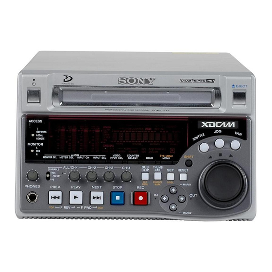
Sony PDW-1500 Operation Manual
Professional disc recorder
Hide thumbs
Also See for PDW-1500:
- Operation manual (154 pages) ,
- Brochure (28 pages) ,
- Brochure & specs (18 pages)

Related Manuals for Sony PDW-1500


Summary of Contents for Sony PDW-1500
- Page 1 PROFESSIONAL DISC RECORDER PDW-1500 OPERATION MANUAL [English] 1st Edition (Revised 3)
-
Page 2: Important Safety Instructions
Do not install the appliance in a confined space, such as a Important Safety Instructions book case or built-in cabinet. • Read these instructions. This apparatus is provided with a main switch on the rear • Keep these instructions. panel. Install this apparatus so that user can access the main •... - Page 3 If you have questions on the use of the above Power Cord/ CAUTION Use of controls or adjustments or performance of procedures Appliance Connector/Plug, please consult a qualified service other than those specified herein may result in hazardous personnel. radiation exposure. VAROITUS! LAITTEEN KÄYTTÄMINEN MUULLA KUIN TÄSSÄ...
- Page 4 De batterij mag alleen vervangen worden door vakbekwaam servicepersoneel. • Lever het apparaat aan het einde van de levensduur in voor recycling, de batterij zal dan op correcte wijze verwerkt worden. For the Customers in Taiwan only...
-
Page 5: Table Of Contents
Table of Contents Before Using the Unit ......7 4-1-2 Recording Time Code and User Bit Setting the Line Mode ........7 Values ..........43 4-1-3 Recording Operation......46 4-1-4 Auto Clip List Recording for Automatic Chapter 1 Overview Inclusion of Recorded Clips in Clip Lists 1-1 Features .......... - Page 6 7-1-3 Assigning User-Defined Clip Titles 76 7-1-4 Assigning User-Defined Clip and Clip List Names ........77 7-2 File Access Mode File Operations... 79 7-2-1 Making FAM Connections ....79 7-2-2 Operating on Files ......80 7-2-3 Exiting File Operations....80 7-3 FTP File Operations ......81 7-3-1 Making FTP Connections ....
-
Page 7: Before Using The Unit
Setting Line mode Before Using the Unit 625: PAL When the desired setting appears, release the SHUTTLE button. Setting the Line Mode “Push SET !!” appears. This unit is shipped with the line mode still unset. Therefore you need to set the line mode before using the unit. - Page 8 Item Item name Settings 525 (U)/525 (J) 625 Basic menu CHARACTER H- 00 to 0A to 2A 00 to 09 to 29 POSITION CHARACTER V- 00 to 2E to 38 00 to 37 to 43 POSITION Extended menu VITC POSITION 12H to 16H to 9H to 19H to SEL-1...
-
Page 9: Chapter 1 Overview
IMX or DVCAM data. It can be transferred quickly over computer networks, easily edited in the field The PDW-1500 has jog and shuttle dials as a conventional with laptop computers, and readily used in a wide variety VTR to search picture in a clip. The jog dial is for frame- of applications, such as content management on small- by-frame search at –1 to +1 times normal speed and the... - Page 10 Supports a variety of interfaces hardware’s status in real time via a TCP/IP network. If a The PDW-1500 supports a variety of interfaces and is malfunction is detected, this system can immediately suitable for use with various nonlinear editing systems.
-
Page 11: Mpeg-4 Visual Patent Portfolio License
1-2 MPEG-4 Visual Patent Portfolio License This product is licensed under the MPEG-4 Visual Patent Portfolio License. For the personal and non-commercial use of a consumer for (i) encoding video in compliance with the MPEG-4 Visual Standard (“MPEG-4 Video”) and/or (ii) decoding MPEG-4 Video that was encoded by a consumer engaged in a personal and non-commercial activity and/or was obtained from a video provider licensed by MPEG LA to provide MPEG-4 Video. -
Page 12: Chapter 2 Names And Functions Of Parts
Names and Functions of Parts Chapter 2-1 Front Panel 7 HOLD button 1 On/standby switch and indicator 8 MENU button EJECT 2 ACCESS indicator SG DATA SG DATA SG DATA SG DATA REMOTE [ 9P iLINK ] EDIT KEY INH ACCESS ALARM ANA SDI... - Page 13 When the indicator is lit green, pressing the switch makes “RECORDING FORMAT” is set to “IMX 50,” “IMX40,” the indicator flash. When the PDW-1500 is in the standby or “IMX 30.” E-E video display and audio output are also state, the indicator lights red.
-
Page 14: Menu Button
The same information is also 1 Audio level meters superimposed on the display on a monitor connected to the 2 Audio input display PDW-1500 (see page 94). Press once more to return to the original display. SG DATA SG DATA... - Page 15 2 Audio settings section The factory default is for channels 1 to 4 to be selected. d AUDIO INPUT CH (channel) button This selects the channel to which the audio input signal 1 MONITOR switch selection applies. 2 AUDIO MONITOR SEL button Pressing this button cycles through the following states of 3 AUDIO METER SEL button the audio level meter channel display.
- Page 16 3 Audio level adjustment section Reverse direction high-speed search: Hold down the PLAY button, and press this button. A high-speed search in the reverse direction is carried out. ALL indicator Displaying the first frame of the first clip: Hold down the SHIFT button, and press this button.
- Page 17 This lights when condensation user bit information, as selected by the COUNTER within the PDW-1500, a laser diode fault, or another SELECT button (see page 13) and extended menu item hardware error is detected. It goes off when the error 629 “TC SELECT.”...
- Page 18 Disc loaded mark b (green): Lights during playback in the reverse direction. This lights while a disc is loaded in the PDW-1500. It B (green): Lights during playback in the forward direction. flashes as the disc is inserted, and while it is being ejected.
- Page 19 a F/MARK1 button and f/MARK2 button mode directly by turning the dial (set extended menu item 101 “SELECTION FOR SEARCH DIAL ENABLE” to When the THUMBNAIL button (see page 14) is lit, you “dial”). can use these for thumbnail selection. During recording and playback, the F/MARK1 and f/ f Shuttle dial MARK2 buttons can be pressed with the SET button held...
-
Page 20: Rear Panel
Follow the instructions in this manual when making pushing it straight in. connections. • When the PDW-1500 is connected to a device with a 6- pin i.LINK connector by an i.LINK cable, before e AUDIO MONITOR OUT connector (RCA-pin) unplugging the i.LINK cable, first power off the device... - Page 21 a DIGITAL AUDIO (AES/EBU) IN (digital audio 1 Analog audio signal inputs/outputs input) 1/2, 3/4 connectors (BNC type) These input AES/EBU format digital audio signals. The 1 AUDIO IN 1/3, 2/4 connectors left connector (1/2) corresponds to audio channels 1 and 2, 2 AUDIO OUT 1/3, 2/4 connectors and the right connector (3/4) corresponds to audio channels 3 and 4.
-
Page 22: Power Supply Section
The output from the VIDEO OUT2 (SUPER) connector on/standby switch indicator on the front panel is lit red (the can have time code, menu settings, alarm messages, and PDW-1500 is in the standby state), then press this switch other text information superimposed. on the a side. -
Page 23: Chapter 3 Preparations
Note Production of some of the peripherals and related devices described in this chapter has been discontinued. For advice about choosing devices, please contact your Sony dealer or a Sony sales representative. 3-1-1 Connecting an External Monitor Connecting a video monitor to the VIDEO OUT 1, VIDEO... -
Page 24: Connections For Using Pdz-1 Proxy Browsing Software
For details of the network-related settings, see “To change Protocol) connection. network settings” (page 116). Note To use PDZ-1 requires the PDW-1500 IP address and other network-related settings to be made beforehand. Connecting this unit directly to a laptop computer 1: Network cable (not supplied) - Page 25 Connecting three PDW-1500 units to a laptop computer via a LAN. 1: Network cable (not supplied) (network) connector PDW-1500 Laptop computer (network) connector PDW-1500 To network connector (network) connector PDW-1500 Make sure the remote control switch (see page 13) is set to “NETWORK”...
-
Page 26: Connecting To A Nonlinear Editing System
1: i.LINK cable (not supplied) Laptop computer S400 (i.LINK) To i.LINK (IEEE1394) connector PDW-1500 Make sure extended menu item 215 “i.LINK MODE” is set to “FAM (PC REMOTE).” 3-1-3 Connecting to a Nonlinear Editing System You can send video/audio signals (AV/C data) from this •... -
Page 27: Connections For Cut Editing
RECORDER PLAYER-1 AC IN BVE-700 REF.VIDEO IN PDW-1500 (player) settings MSW-M2000/M2000P (recorder) settings Remote control switch (see page 13): REMOTE REMOTE 1(9P) button: Lit Extended menu item 214 “REMOTE INTERFACE”: 9PIN For details about the settings of the MSW-M2000/M2000P, refer to the operation manual for the unit. - Page 28 REMOTE COMPOSITE VIDEO MSW-M2000/M2000P OUTPUT 3(SUPER) (recorder) PDW-1500 (player) settings MSW-M2000/M2000P (recorder) settings Remote control switch (see page 13): REMOTE REMOTE 1(9P) button: Unlit Extended menu item 214 “REMOTE INTERFACE”: 9PIN For details about the settings of the MSW-M2000/M2000P, refer to the operation manual for the unit.
-
Page 29: Connections For Clip Audio Insert
PDW-1500 (player) DSR-2000/2000P VIDEO OUT 3(SUPER) (recorder) DSR-2000/2000P (recorder) settings PDW-1500 (player) settings Remote control switch (see page 13): REMOTE i.LINK button: Lit SDTI/i.LINK button: i.LINK Extended menu item 214 “REMOTE INTERFACE”: i.LINK For details about the settings of the DSR-2000/2000P, refer to the operating instructions for the unit. - Page 30 (player) RECORDER AC IN PLAYER-1 REF.VIDEO IN BVE-700 PDW-1500 (recorder) settings MSW-M2000/M2000P (player) settings Remote control switch (see page 13): REMOTE REMOTE 1(9P) button: Lit Extended menu item 214 “REMOTE INTERFACE”: 9pin For details about the settings of the MSW-M2000/ BVE-700 settings M2000P, refer to the operation manual for the unit.
- Page 31 (player) RECORDER AC IN PLAYER-1 REF.VIDEO IN BVE-700 PDW-1500 (recorder) settings MSW-M2000/M2000P (player) settings Remote control switch (see page 13): REMOTE REMOTE 1(9P) button: Lit Extended menu item 214 “REMOTE INTERFACE”: 9pin For details about the settings of the MSW-M2000/ M2000P, refer to the operation manual for the unit.
- Page 32 (player) RECORDER AC IN PLAYER-1 REF.VIDEO IN BVE-700 PDW-1500 (recorder) settings MSW-M2000/M2000P (player) settings Remote control switch (see page 13): REMOTE REMOTE 1(9P) button: Lit Extended menu item 214 “REMOTE INTERFACE”: 9pin For details about the settings of the MSW-M2000/ M2000P, refer to the operation manual for the unit.
-
Page 33: Editing Control Unit Settings
3-1-6 Editing Control Unit Settings When connecting an editing control unit to use with this unit, make the following settings, depending on the editing control unit model. BVE-600/700/900/910/2000/9100 Set VTR constants as follows. Line VTR CONSTANT 1 VTR CONSTANT 2 mode 525/60 625/50... -
Page 34: Setup
3-2 Setup 3-3 Setting the Date and Time The principal setup operations before operating this unit can be carried out using setup menus. When using this unit for the first time, you should set the The setup menus of this unit comprise a basic setup menu date and time as follows. -
Page 35: Superimposed Text Information
Note 3-4 Superimposed Text The time zone is reset to the factory default when you execute the maintenance menu item “RESET ALL Information SETUP.” You will need to set it again. The date and time are not reset. The video signal output from the VIDEO OUT 2 (SUPER) connector or the SDI OUT 2 (SUPER) connector contains superimposed text information, including time code, menu settings, and alarm messages. - Page 36 a Type of time data f Operation mode The field is divided into two blocks as shown below. Display Meaning • Block A displays the operation mode. • Block B displays the servo lock status or playback speed. Counter data TC reader time code data TC reader user bits data TCR.
- Page 37 • Deteriorating laser diodes performance Display Name Description The performance of the laser diodes used in optical heads can worsen with age, leading to deteriorating Green condition There is no problem with the playback condition. This unit playback conditions. and the disc can be used just You can use the digital clock to check the total optical as they are.
-
Page 38: Handling Discs
Playback This disc recorder uses the following disc for recording and playback: PFD23 Professional Disc (capacity 23.3 1) Professional Disc is a trademark of Sony Corporation. Note It is not possible to use the following discs for recording or playback: Slide in the direction of the arrow •... -
Page 39: Formatting A Disc
To format several discs in succession 3-5-5 Formatting a Disc An unused disc requires no formatting operation. The disc Carry out steps 1 to 5 in the previous procedure, and is automatically formatted when loaded into this unit. then press the EJECT button to eject the disc. To format a recorded disc, load the disc into the unit, then proceed as follows. - Page 40 • This function salvages as much recorded material as Sections which were recorded normally can be played possible after an unforeseen accident, but 100% back, but no new recording can be done on the disc. (A restoration cannot be guaranteed. quick format can be done on the disc, although all of •...
-
Page 41: Chapter 4 Recording/Playback
Recording/Playback Chapter 4-1 Recording This section describes video and audio recording on the unit. 4-1-1 Preparations for Recording Button/switch settings For details of the settings of the buttons/switches, see the pages indicated in parenthesis. Before beginning recording, make any necessary button/ switch settings. - Page 42 Setting the recording format To adjust the audio recording levels Before recording, it is necessary to set the recording format When carrying out audio recording at a reference for each of video and audio. level Set the VARIABLE switch (see page 16) to PRESET. The Note audio signals will be recorded at a preset reference level.
-
Page 43: Recording Time Code And User Bit Values
4-1-2 Recording Time Code and User Bit Values There are the following four ways of recording time code: - TIME CODE IN connector: LTC • Internal Preset mode, which records the output of the - VIDEO IN connector: VITC internal time code generator, set beforehand to an initial - SDI IN connector: SMPTE RP188 LTC value. - Page 44 To set time code to the current time With extended menu item 627 “RUN MODE” set to “free Indicators above the time run” and 628 “DF MODE” to “on (df),” do as follows. data display For details of the extended menu operations, see 8-3-2 Time data display “Extended Menu Operations”...
- Page 45 In this case, the setting of extended menu item 628 “DF To synchronize to SMPTE RP188 LTC in an SDI MODE” is ignored. New time code is recorded in the drop- signal frame mode of the last recorded time code on the disc. Connect an SDI signal containing SMPTE RP188 LTC to the SDI IN connector.
-
Page 46: Recording Operation
extended menu item 626 “TC MODE” to “ext regen” Connect the time code output from the external device automatically synchronizes the internal time code to the TIME CODE IN connector. Press the VIDEO generator to the time code received through the S400 INPUT SEL button and, while viewing the INPUT (i.LINK) connector or SDI IN connector. -
Page 47: Auto Clip List Recording For Automatic Inclusion Of Recorded Clips In Clip Lists
To change the registered clip list, repeat step 2 to load Notes the desired clip list. • The shortest clip that can be recorded is 2 seconds long. Even if recording start and stop operations are performed To exit auto clip list recording mode within 2 seconds, a 2-second clip is recorded. -
Page 48: Playback
To play back a clip, press the PREV button to move to the 4-2 Playback start frame of any clip, or press the PREV button with the PLAY button held down to move to any position. After disc insertion This section describes playback of video and audio. The unit stops at the position of the disc when it was most recently ejected. -
Page 49: Playback Operation
For information about the functions of these buttons, see 4-2-2 Playback Operation “4 Recording and playback control section” on page 16. For details of the jog and shuttle dials, see “6 Shuttle/jog/ This section describes the following types of playback: variable control block”... -
Page 50: Thumbnail Search
setting), just turning the jog dial with the JOG button off To carry out playback in variable speed mode, do as starts playback in jog mode. follows. Playback in shuttle mode In shuttle mode, you can control the speed of playback by the angular position of the shuttle dial. - Page 51 Press the THUMBNAIL button, turning it off. COUNTER SELECT button Use the arrow buttons or the jog dial to select the desired clip. You can select clips with the following operations. EJECT Press the PREV or NEXT button: Move to the previous or next clip.
-
Page 52: Clip List Playback
To escape from the essence mark selection screen to 4-2-4 Clip List Playback the previous screen Press the RESET button. You can play back clips in the order of clip lists created with the scene selection function (see page 56). Use the arrow buttons or the jog dial to select the desired essence mark. -
Page 53: Repeat Playback
To perform repeat playback, set extended menu item 142 Sixth frame is selected “REPEAT MODE” to “play,” and then proceed as follows. Name of current clip list from a total of 34 sub clips 1) This is supported from firmware version 1.4. Total duration of sub clips in clip list Insert a disc. -
Page 54: Locking And Deleting Clips
With LOCK/UNLOCK CLIP selected, press the SET 4-2-6 Locking and Deleting Clips button. In the thumbnail screen, you can delete selected clips or You return to the thumbnail screen, and a lock icon lock them so that they cannot be deleted. appears on the thumbnail of the selected clip to show that it is locked. -
Page 55: Deleting Clips
Use the G or g button to select “OK,” and then press When the target clip is referenced in a clip list: the SET button. “DELETE CLIP & CLIP LIST?” (The clip list that references the clip will also be deleted.) All clips are locked, and you return to the thumbnail screen. -
Page 56: Chapter 5 Scene Selection
Scene Selection Chapter 5-1 Overview What is scene selection? Scene selection is a function which allows you to select material (clips) from the material recorded on a disc and perform cut editing. You can do this by operating on this unit only. - Page 57 Flow of scene selection editing Disc Insert disc containing recorded material into this unit PDW-1500 PDW-510/530 To edit a clip list Load clip lists (see page 66) Create and edit a clip list • Selecting clips (see page 59) Clip 1...
- Page 58 Clips Clip list name Material recorded on a disc with this unit is managed in units called “clips.” A clip contains the material between a recording start point (In point) and a recording end point (Out point). Clips have names beginning with “C,” for example “C0001.”...
-
Page 59: Creating Clip Lists
5-2 Creating Clip Lists Unit memory Current clip list t Clip list playback Can be edited (adding, deleting, and thumbnail and reordering sub clips) display Before starting Insert a disc containing recorded clips into the unit. SAVE M LOAD Disc 5-2-1 Selecting Clips There are two ways to select clips. - Page 60 The scene selection window displays thumbnails of the sub clips that have been added to the current clip list. The cursor in the window indicates the position where the next sub clip will be added. Total duration of sub clips in the current clip list Use the arrow buttons or the jog dial to select the desired clip.
-
Page 61: Reordering Sub Clips
Repeat steps 1 to 4 until you have added all of the clips you want to the current clip list. Save the current clip list to disc. See 5-2-6 “Saving the Current Clip List to Disc” (page 64). 5-2-2 Reordering Sub Clips THUMBNAIL button To search SET button... - Page 62 Load the clip list from the disc into the unit memory (see page 66). Indicates that the third sub clip will be moved to the position of the eighth sub clip. To return to the full-screen display Press the THUMBNAIL button, turning it on. Use the arrow buttons or the jog dial to select the desired sub clip.
-
Page 63: Trimming Sub Clips
At the scene where you want to set a new In or Out 5-2-3 Trimming Sub Clips point, hold down the G/IN button (to change the In point) or the g/OUT button (to change the Out point) and press the SET button. THUMBNAIL button Depending on the button that you pressed, a new In or SET button... -
Page 64: Deleting Sub Clips
5-2-4 Deleting Sub Clips SET button RESET button EJECT SG DATA SG DATA SG DATA SG DATA EDIT REMOTE [9P iLINK] KEY INH ACCESS ALARM ANA SDI ANA SDI ANA SDI ANA SDI INPUT AE8/EBU AE8/EBU AE8/EBU AE8/EBU VITC VIUB COUNTER VITC REC INH... - Page 65 SAVE CLIP LIST SET button EJECT SAVE E0005 OK ? SG DATA SG DATA SG DATA SG DATA REMOTE [9P iLINK] ACCESS EDIT KEY INH ALARM ANA SDI ANA SDI ANA SDI ANA SDI INPUT AE8/EBU AE8/EBU AE8/EBU AE8/EBU VITC VIUB COUNTER VITC...
-
Page 66: Managing Clip Lists (Clip Menu)
Item Operation 5-3 Managing Clip Lists LOAD Load a clip list from the disc into the current (CLIP Menu) clip list (see page 66) Save the current clip list to disc (see page SAVE After you create a clip list, you can use the CLIP menu to Delete a clip list from the disc (see page 67) DELETE save it to disc, load it from disc into the unit memory, and... -
Page 67: Deleting Clip Lists From A Disc
Use the F or f button or the jog dial to select the Use the F or f button or the jog dial to select the desired clip list, and then press the g button desired clip list, and then press the g button. A confirmation message like the one shown below A confirmation message like the one shown below appears. -
Page 68: Sorting Clip Lists
“00:00.00.00.” You can set the initial time code to any 5-3-5 Sorting Clip Lists value. Proceed as follows to sort the existing clip lists by clip list Load an existing clip list for which you want to set the name or by date of creation. initial time code into to the unit memory as the current clip list. -
Page 69: Using Pdz-1 Proxy Browsing Software
adequate free space. The amount of proxy AV data 5-4 Using PDZ-1 Proxy transferred is about 1.4 GB per disc (when recording in the DVCAM format). Browsing Software • To transfer files between the computer and this unit requires this unit’s IP address and other network-related settings to be made. -
Page 70: Chapter 6 Insert Editing
Insert Editing Chapter Number of editable audio tracks 6-1 Clip Audio Insert The audio tracks in clips can be edited independently. The number of editable audio tracks differs as follows Editing depending on the clip’s recording format. • IMX format: 8 or 4 channels •... -
Page 71: Editing Operations
Item Setting Number of audio Check the number of audio channels recorded in the clip and the number of quantizing bits with the AUDIO indicators (see page 18), and set the audio format to the same number of recording recording channels and number of quantizing bits channels and quantizing bits with the maintenance menu item “AUDIO CONFIG - “DATA LENGTH”... - Page 72 Press the AUDIO INPUT SEL button (see page 15) to select the input signal. Set MIXING in extended menu item 819 “AUDIO INPUT SOURCE ARRANGE” to “on,”and set CH1 to “on.” See 8-3-2 “Extended Menu Operations” (page 109) for more information about how to make these settings.
-
Page 73: Chapter 7 File Operations
File Operations Chapter 7-1 Overview root INDEX.XML A remote computer can be connected to this unit and used to operate on recorded data which has been saved in data ALIAS.XML files, such as video and audio data files. DISCMETA.XML There are two ways to connect a remote computer. •... -
Page 74: File Operation Restrictions
7-1-2 File Operation Restrictions This section explains which operations are possible on Partial read: Read only a part of the data in the file. files stored in each directory. Overwrite: Overwrite data sequentially from the start When required, the following operation tables distinguish to the end of the file. - Page 75 h) When a C*.MXF file is deleted, the C*M01.XML file with the same name clips on that disc. (The only possible operations are in the “C*” part is also deleted automatically. playback and disc formatting.) - Writing of clips with user-defined names Notes - Locking of clips •...
-
Page 76: Assigning User-Defined Clip Titles
General directory File name Content Operations Read/ Overwrite/ Rename Create Delete Partial read Partial overwrite Any file a) UTF-8 file names can be up to 63 bytes in length. (Depending on the character type, file names (including extension) may be limited to 21 characters.) b) Only when the write inhibit tab on the disc is set to enable recording, and C0020.MXF... -
Page 77: Assigning User-Defined Clip And Clip List Names
With the STOP button held down, rotate the jog or 7-1-4 Assigning User-Defined Clip shuttle dial to move the asterisk (*) on the left of the and Clip List Names menu items to “TITLE.” The asterisk indicates the selected item. The following standard format names are assigned automatically to clips and clip lists that are created or With the SHUTTLE button held down, rotate the jog... - Page 78 With the STOP button held down, rotate the jog dial or the shuttle dial to move the “*” to the left of “AUTO NAMING.” C0001.MXF With the SHUTTLE button held down, rotate the jog dial or the shuttle dial to select “title.” Press the SET button.
-
Page 79: File Access Mode File Operations
- The user-defined name or standard format name is 7-2 File Access Mode File displayed for clips without a title. • If the firmware of your XDCAM device is version 1.4x Operations or lower, clips with user-defined names appear as “C5000”... -
Page 80: Operating On Files
To log in, disconnect the cable, put the unit into the appears. state described in step 1, and connect it again. Select “Sony XDCAM PDW-1500 IEEE 1394 SBP2 Operation limitations during FAM connections Device” and click Stop. • Front panel operations are disabled, except for operations with the EJECT button. -
Page 81: Ftp File Operations
To disable FAM connections 7-3 FTP File Operations Execute one of the procedures described in the previous section “Reconnecting” to make a FAM connection between this unit and the remote computer. To disable FAM connections, set extended menu item 215 “i.LINK File operations between this unit and a remote computer MODE”... - Page 82 When the user name is verified, you are prompted to enter a password. Enter the password and press the Enter key. The password is set to “pdw-1500” when the unit is shipped from the factory. The login is complete when the password is verified.
-
Page 83: Command List
PASS After sending the USER command, PASS <SP> <password> <CRLF> send this command to complete the login process. Input example: PASS pdw-1500 QUIT Terminates the FTP connection. If a file QUIT <CRLF> is being transferred, terminates after completion of the transfer. - Page 84 Command name Description Command syntax STRU Specifies the data structure. STRU <SP> <structure-code> <CRLF> <structure-code> can be any of the following. However, for XDCAM, the structure is always “F,” regardless of the structure-code specification. • F: File structure (default) • R: Record structure •...
- Page 85 Command name Description Command syntax STOR Begins transfer of a copy of a file in the STOR <SP> <path-name> <CRLF> specified path on the remote computer to the current directory on this unit. Input example: STOR Edit/E0001E01.SMI Depending on the type of file transferred, the following files are created.
- Page 86 Command name Description Command syntax STAT Sends information about properties of STAT <SP> <path-name> <CRLF> the specified file, or about data transfer status, from this unit to the remote The following data is transferred, depending on whether a file computer. is specified with <path-name>.
- Page 87 Extended commands The following table shows the extended FTP commands In the Command syntax column, <SP> means a space, supported by this unit. entered by pressing the space bar, and <CRLF> means a new line, entered by pressing the Enter key. Command name Description Command syntax...
- Page 88 Command name Description Command syntax Locks and unlocks clips. Also sets SITE CHMOD <SP> <flag> <SP> <path-name> <CRLF> SITE CHMOD permissions for directories and files in the General directory. Specify one of the following values in <flag>, according to the specification in <path-name>. •...
-
Page 89: Recording Continuous Time Code With Fam And Ftp Connections
7-4 Recording Continuous Time Code With FAM and FTP Connections When you are connected to the unit by FAM or FTP, you can create new clips with time code that is continuous with the time code of the last frame of the last clip on the disc. To record continuous time code, set extended menu item 626 “TC MODE”... -
Page 90: Menu System Configuration
Menus Chapter Item group Function Refer to 8-1 Menu System page 121 Items Display of the total number of Configuration H01 to H17 hours the unit has been powered on, and other information collected by the digital hours meter The settings for this unit use the following menus. page 91 Items Settings relating to the preroll... -
Page 91: Basic Setup Menu
8-2 Basic Setup Menu 8-2-1 Items in the Basic Setup Menu The basic menu items (excluding the items related to the • An abbreviated name appears in the time data display digital hours meter) are listed in the following table. section when you press the NEXT button. - Page 92 Item number Item name Settings CHARACTER TYPE Determine the type of characters such as time code output from the VIDEO OUT 2 (SUPER) connector and SDI OUT 2 (SUPER) connector for superimposed display on the monitor. white: White letters on a black background. black: Black letters on a white background.
- Page 93 Item number Item name Settings STORED OWNERSHIP Specify whether to enable changing UMID ownership information settings (COUNTRY, ORGANIZATION and USER). off: Do not enable. on: Enable. See 8-3-3 “Using UMID Data” (page 110) for more information about UMID. RECORDING FORMAT Select the recording format.
-
Page 94: Basic Menu Operations
Item number Item name Settings RESET SETUP MENU Set to “on” to return the settings of the current menu to the factory default settings. Set to “bank-4” to set the current menu to the settings saved in menu bank 4. on (on (default)): Return the current menu to the factory default settings. - Page 95 Changing the currently displayed menu item EJECT SG DATA SG DATA SG DATA SG DATA REMOTE [9P iLINK] ACCESS EDIT KEY INH ALARM ANA SDI ANA SDI ANA SDI ANA SDI INPUT AE8/EBU AE8/EBU AE8/EBU AE8/EBU VITC VIUB COUNTER VITC REC INH i.LINK OVER...
- Page 96 Turn the unit off (press the on/standby switch to put the unit in the standby state). Next time the unit is turned on (when the unit is put in the operating state by pressing the on/standby switch), it operates in the new mode. EJECT Menu bank operations (menu items B01 to SG DATA...
- Page 97 To cancel the recall, press the MENU button. Recall Current active Menu bank 1 menu settings Save Recall Menu bank 2 Save Recall Menu bank 3 Save Recall Menu bank 4 Save Note The following message appears if the line mode of the menu bank that you are about to recall differs from the current line mode.
-
Page 98: Extended Menu
8-3 Extended Menu 8-3-1 Items in the Extended Menu The following tables show the items in the extended menu. • The values in the Settings columns are the values which • Item names are the names which appear on an external appear in the time data display section. - Page 99 Menu items in the 100s, relating to the control panels Item number Item name Settings Specify the frame mode for variable speed playback. FRAME PB MODE field: Field playback frame: Frame playback. Compared to field playback, frame playback gives still pictures with higher precision. DISPLAY DIMMER CONTROL Set the brightness of the audio level meters.
- Page 100 Menu items in the 300s, relating to editing operations Item number Item name Settings VAR SPEED RANGE FOR Select the playback speed range when carrying out playback in variable SYNCHRONIZATION speed mode from a remote control unit connected to the REMOTE connector.
- Page 101 Menu items in the 300s, relating to editing operations Item number Item name Settings OUTPUT REFERENCE SEL Select the reference signal of this unit. ref (ref. video): Use the signal input to the REF. VIDEO IN connector as the reference signal. auto: According to the operation mode, automatically select either the signal input to the REF.
- Page 102 c) Synchronize to the signal input to the SDI IN connector. If no signal is d) No external synchronization is made. input to the connector, no synchronization is made. Menu items in the 400s, relating to preroll Item number Item name Settings FUNCTION MODE AFTER CUE-UP Select the state that the unit goes into after a cuing-up operation.
- Page 103 Menu items in the 600s, relating to the time code, metadata, and UMID Item number Item name Settings U-BIT BINARY GROUP FLAG Select the user bits to be used in the time code generated by the time code generator. 000 (000:not specified): Character set not specified. 001 (001:iso character): 8-bit characters compliant with ISO 646 and ISO 2022.
- Page 104 Menu items in the 600s, relating to the time code, metadata, and UMID Item number Item name Settings TC SELECT Select the type of time data to show in the time data display, and the type of external time code when item 626 is set to “ext regen.” vitc: Display time code as VITC, or select VITC as the external time code.
- Page 105 Menu items in the 700s, relating to video control Item number Item name Settings BLANK LINE SELECT Switch blanking of the video output signal on or off for individual lines in the vertical blanking interval. Sub-item The Y/C signal and odd/even fields are blanked simultaneously. ALL LINE - - -: Specify the blanking for each line separately.
- Page 106 Menu items in the 700s, relating to video control Item number Item name Settings VIDEO SETUP REFERENCE Select whether to remove the setup (7.5%) from the input analog video signals and whether to add the setup (7.5%) to the output analog video signals (when 525(U) or 525(J) line mode is selected).
- Page 107 Menu items in the 700s, relating to video control Item number Item name Settings Specify whether to record and play back with the addition of wide picture WIDE MODE information. Sub-item INPUT Specify whether to save wide picture information on a disc during recording.
- Page 108 Menu items in the 800s, relating to audio control Item number Item name Settings AUDIO INPUT SOURCE ARRANGE Enable or disable mixing of the audio signals of channels 1 to 8 into the audio signals of the same channels recorded on the disc. Sub-item MIXING off: Do not mix.
-
Page 109: Extended Menu Operations
Menu items in the 800s, relating to audio control Item number Item name Settings SDI/DV AUDIO OUTPUT SELECT Select the audio signals to assign to SDI and i.LINK(AV/C) audio output channels. Sub-item CH1/CH2 tr1/2: Tracks 1 and 2 assigned to audio output channels 1 and 2. tr3/4: Tracks 3 and 4 assigned to audio output channels 1 and 2. -
Page 110: Using Umid Data
The menu appears in the time data display. Hold down the COUNTER SELECT button, and press the SET button. In the time data display, first “MAINTE MENU” appears momentarily, and then the item group name appears. Using the F/f buttons, display “Setup” in the time data display. - Page 111 Extended UMID (64 bytes) Basic UMID (32 bytes) Source Pack (32 bytes) Spatial Universal label Inst. No. Material Number Time/Date Country User Co-ordinates 12 bytes 3 bytes 16 bytes 8 bytes 12 bytes 4 bytes 4 bytes 4 bytes Globally unique ID is automatically recorded in clip units. The UMID is applied as follows.
- Page 112 Hold down the SHUTTLE button, and turn the jog dial Note or shuttle dial. User code cannot be entered when no organization code has been entered. Press the SET button. About UMID ownership information COUNTRY (country code) Enter an abbreviated alphanumeric string (4-byte alphanumeric strings) according to the values defined in ISO 3166-1.
-
Page 113: Maintenance Menu
8-4 Maintenance Menu 8-4-1 Items in the Maintenance Menu The following tables show the items in the maintenance appear in a different format on an external monitor. In menu. this case, the external monitor values are shown in • Item names are the names which appear on an external parentheses.) Underlined values are the factory defaults. - Page 114 NETWORK CONFIG: items relating to network settings Item Setting SUBNET MASK PRESET Set the subnet mask. 255.255.255.000 Note When DHCP is set to “ENABLE,” it is not possible to set the subnet mask. DEFAULT GATEWAY PRESET Set the default gateway. 000.000.000.000 Note When DHCP is set to “ENABLE,”...
-
Page 115: Maintenance Menu Operations
OTHERS Item Setting SDI2 SUPER Select whether to output superimpose characters to the SDI OUT2 (SUPER) connector. ON: Output. OFF: Do not output. For details about OTHERS items other than the above, The item name appears. refer to the Maintenance Manual. 8-4-2 Maintenance Menu Operations This section describes the indications in the maintenance menu and how to change the settings. - Page 116 Press the g button. Press the f button, to display “>> ENABLE.” EJECT Press the SET button. SG DATA SG DATA SG DATA SG DATA REMOTE [9P iLINK] ACCESS EDIT KEY INH ALARM ANA SDI ANA SDI ANA SDI ANA SDI INPUT AE8/EBU AE8/EBU...
- Page 117 Turning clockwise increases the value, and turning counterclockwise decreases the value. The F/f buttons can be used. To return to the factory default setting Press the RESET button. When all digits are set, press the SET button. This returns to the NETWORK CONFIG menu. To cancel a setting Before pressing the SET button, press the MENU button.
-
Page 118: System Menu
8-5 System Menu 8-5-1 Items in the System Menu The following tables show the items in the system menu. Item names are the names which appear on an external monitor to which the output of the VIDEO OUT 2 (SUPER)/SDI OUT 2 (SUPER) connector is input. DISC MENU: items relating to disc Item Setting... -
Page 119: System Menu Operations
CLIP ESSENCE S.SEL TITLE: (no name) MARK1 MENU MARK PHONES NEXT PREV PLAY STOP RECORD DEVICE: PDW-1500 F REV F FWD MARK2 SERIAL: 10001 DATE 01/01/06 TIME 19:54:38 Arrow buttons SET button TO MENU : MENU KEY To return to the previous menu page To display disc status and clip status Press the MENU button. - Page 120 Press the F button or f button to select “ALL CLIP,” then press the g button. The message “ALL DELETE OK?” appears. To cancel the deletion and return to the previous page, press the RESET button. To cancel the deletion and exit the menu system, press the MENU button.
-
Page 121: Chapter 9 Maintenance And Troubleshooting
The count is resettable. For periodic maintenance, consult your Sony dealer. 1) The counter advances at different rates during recording and playback. It is also affected by the ambient temperature. -
Page 122: Error Messages
9-2 Error Messages MENU button EJECT Error codes appear in the time data display when an error (usually a hardware problem) occurs. Error codes and error SG DATA SG DATA SG DATA SG DATA EDIT REMOTE [9P iLINK] KEY INH ACCESS ALARM ANA SDI... -
Page 123: Alarms
9-3 Alarms An alarm (warning message) appears in the time data display when an operation is attempted which is inappropriate for the settings on this unit or the state of the disc. The monitor connected to this unit displays the alarm message and also the action to take to resolve the problem. - Page 124 Exchg batt! on, limit, off NVRAM battery is exhausted. It is time to exchange the battery on the board. Contact your Sony service representative. a) With respect to setting of basic menu item 016 When a disc is inserted Message in time...
- Page 125 Message in time Display Description Action data display condition ILL. Index! on, limit, off An index file error was detected. Format the disc. For details, see 3-5-5 “Formatting a Disc” (page 39). FORMAT NG! on, limit, off Automatic format failed. Use another disc.
- Page 126 Message in time Display Description Action data display condition IMX50 Clip on, limit A recording, E-E display, or edit preset To perform these operations on the disc, IMX40 Clip operation was attempted on a disc change the setting of basic menu item 031. IMX30 Clip recorded in a format different from the See 8-2-2 “Basic Menu Operations”...
- Page 127 Message in time Display Description Action data display condition TC EXT! A time code or user bits preset operation Try the operation again after setting was attempted with extended menu item extended menu item 626 “TC MODE” to 626 “TC MODE” set to “ext preset.” “int preset.”...
- Page 128 Message in time Display Description Action data display condition Non AV Full on, limit, off An attempt was made to record, display Insert a different disc with enough free an E-E picture, record an essence mark, capacity. or add a quick scene selection sub clip when there was no free Non-Real-Time space.
- Page 129 Message in time Display Description Action data display condition MAX # Files on, limit, off The number of files on the disc had Exchange the disc for one with enough reached the upper limit (5000), or there free capacity. was not enough capacity in the General directory when a command was received to record, display an E-E picture, record an essence mark, or add...
- Page 130 Input a reference video signal to the player system are not synchronized. and recorder. ILL. REC! on, limit A sync error between encoder and input Contact your Sony service representative. signal occurred during recording. ILL. PLAY! on, limit An audio/video phase error occurred during playback.
- Page 131 Action data display condition FAN Stopped on, limit, off The motor of the main unit fan has Contact your Sony service representative. stopped. Note DR-FAN Stop on, limit, off The motor of a drive fan has stopped. The unit will operate, but continued use in...
-
Page 132: Appendixes
Appendixes Specifications General Power requirements 100 V to 240 V AC, 50/60 Hz Power consumption 75 W Peak inrush current (1)Power ON, current probe method: 65 A (240 V), 20 A (100 V) (2)Hot switching inrush current, measured in accordance with European standard EN55103-1: 15 A (230 V) Operating temperature... - Page 133 Recording/Playback time DIGITAL AUDIO (AES/EBU) IN 1/2, 3/4 MPEG IMX BNC type (×2), complying with AES- 50 Mbps: 45 min. 3id-1995 40 Mbps: 55 min. S400 (i.LINK) 30 Mbps: 68 min. 6-pin (×1), complying with IEEE 1394 DVCAM 85 min. Analog video inputs Search speed REF.
-
Page 134: Accessories Supplied
• Always make a test recording, and verify that it was low impedance, balanced recorded successfully. AUDIO MONITOR OUT SONY WILL NOT BE LIABLE FOR DAMAGES OF ANY RCA-pin (L, R, L+R) (×1) KIND INCLUDING, BUT NOT LIMITED TO, COMPENSATION OR REIMBURSEMENT ON –11 dBu, 47 kΩ, unbalanced... -
Page 135: Glossary
through electric circuits only and Proxy AV data Glossary then come out from the output Low-resolution data with a video connectors, without passing through bandwidth of 1.5 Mbps and an audio electromagnetic conversion circuits bandwidth of 64 kbps per channel. such as recording heads. - Page 136 UMID Unique Material Identifier. A standard (SMPTE 330M) for video and audio metadata. The Basic section of a UMID contains a globally unique number and a material number for the identification of recorded material. An optional section called the “Source Pack” contains information such as the time and location of recording.
-
Page 137: Index
119 External monitor connection 23 Index user-defined name 77 Clip list 58 CLIP menu 66 Features of PDW-1500 9 creating and editing 59 File access mode current clip list 58 file operations 79 AC IN connector 22 deleting 67... - Page 138 LOCAL 13 Power supply section 22 deleting 64 POWER switch 22 reordering 61 Preparations 23 trimming 63 PREV button 16 SUBCLIP button 13 Maintenance 73, 121 Proxy AV data 9 Superimposed text information (See periodic 121 Proxy Browsing Software (See also also “Text information”) 35 Maintenance menu 113 “PDZ-1”) 24, 69...
- Page 139 indicator 17 Write-protecting discs 38 Index...
- Page 140 The material contained in this manual consists of information that is the property of Sony Corporation and is intended solely for use by the purchasers of the equipment described in this manual. Sony Corporation expressly prohibits the duplication of any...
- Page 141 Sony Corporation PDW-1500 (SYL) http://www.sony.net/ © 2004 3-796-077-04 (1)