
Related Manuals for Hitachi KP-F1


Summary of Contents for Hitachi KP-F1
- Page 1 Progressive Scan Type Black and White Camera (Frame Shutter) KP-F1 Technical Operation Guide Hitachi Denshi America, Ltd 150 Crossways Park Drive Woodbury, NY 11797 Phone: 516-921-7200 Fax: 516-921-0993...
-
Page 2: Table Of Contents
May 1997 Table of Contents 1. General ………………………………………………………………… 4 Major Features ………………………………………………………... 4 2. External view …………………………………………………………. 5 Tripod Adapter ……………………………………………………….. 5 3. Specifications …………………………………………………………. 6 Composition ………………………………………………………….. 7 Optional Accessories …………………………………………………. 7 Warranty ………………………………………………………………. 8 4. Operating precautions ………………………………………………….8 5. - Page 3 Two trigger mode …………………………………………………… 21 Sync non-reset mode ……………………………………………….. 22 Fixed shutter mode …………………………………………………. 22 15. Non-interlaced operation …………………………………………… 23 16. Timing diagrams …………………………………………………… 17. Image sensor ……………………………………………………….. 30 18. Options ……………………………………………………………… 31...
-
Page 4: General
1. General The Hitachi KP-FI is a full-frame shutter black and white camera using a 1/2" progressive scan CCD. The KP-FI features high performance, high sensitivity, and high resolution. The KP-FI is provided with a variety of functions including a multiple step electronic shutter, integration mode switching, external HD/VD sync input, Field-on-Demand, and non-interlaced scanning functions. -
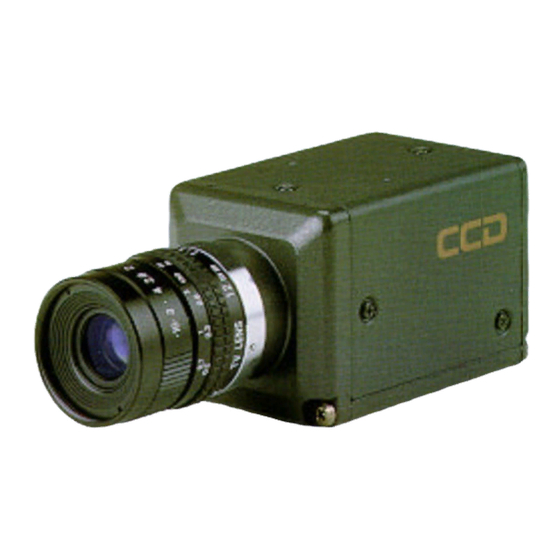
Page 5: External View
sync signal applied. 7) Field-on-Demand function The images captured at an optional timing by an external trigger signal input can be instantly obtained as Images. The timing can be adjusted by an external trigger signal and the shutter. External View Caution installation of the camera use camera mounting holes A, B and C. -
Page 6: Specifications
Specifications Imaging device Interline CCD No. of total pixels EIA: 692 (H) x 504 (V) CCIR: 823 (H) x 592 (V) 9.9 (H) x 9.9 (V) µm Pixel Pitch EIA: CCIR: 8.3 (H) x 8.3 (V)µm No. of effective pixels EIA: 659 (H) x 494 (V) CCIR: 782 (H) x 582 (V) -
Page 7: Composition
Gamma correction 1 (factory setting) or selectable by internal switch Separately settable to two video channels Fixed or AGC: Available to only VIDEO OUT 1 External switch selectable. Fixed = factory setting. Gain selection VIDEO 1 : Fixed or set by knob VIDEO 2 : Fixed The external switch is selectable. -
Page 8: Warranty
3) Hitachi Denshi is not liable for the losses caused when the equipment is used in a system used for business trades, production process, medical fields, crime prevention applications, etc. - Page 9 4-1 Power supply Connect 12V ± IV DC from an external power supply. Use a stable power supply without ripple and noise. 4-2 To protect CCD(sensor) 1) Do not touch the glass surface of the sensor to avoid dirt and scratches. 2) If the glass surface of the sensor should become dusty or dirty, wipe off dust or dirt carefully with a cotton-tipped applicator.
-
Page 10: Name And Function Of Each Section
noise appears. 3) Moire When fine patterns are shot, moire may be displayed. 5. Name and function of each section. 1 Video Out 1 (BNC) Composite video signal (VS) output (VIDEO OUT 1) 2 Video Out 2 (BNC) Composite video signal (VS) output (VIDEO OUT 2) 3 Manual gain control Adjustable when switch 4 is set to M (effective only for Video Out 1) -
Page 11: Connections
6. Signal connection to connector 1) Signal connections to DC IN / SYNC connector (12 pins) Internal External Sync Mode Sync Field-on-Demand Mode Mode HD/VD One Trigger Two Trigger Fixed Shutter Sync N.R. Ground + 12 volt input Video 1 output Ground Video 1 output Signal HD in Trigger B In... -
Page 12: Optical System
2) Signal connection to LENS (trigger) connector (6 pins) Signa FLD pulse output WEN pulse output Trigger C input (SYNC N.R. only) Auto iris video output +12 volts DC Note: • The FLD pulse is not output in the field-on-demand function. •... -
Page 13: Optical Filter
8. Optical Filter The KP-F1 is provided with a IR cut filter, that can be removed if required for a specific application. Removal of the IR cut filter. 1. Remove two screws (1) shown, and filter holder (2) will come off. -
Page 14: Optional Connection
• Supply HD and VD pulses to the KP-F1 when using external sync drive. • The power supply voltage should be between 11 and 13 volts DC and should be free of noise and ripple. • Confirm proper voltage polarity before connecting a external power supply to the KP-F1. -
Page 15: Camera Settings
11. Camera Settings Gamma (y) correction Factory setting is OFF (1.0), but it is changeable if necessary. VIDEO OUT 1 (SW101) and VIDEO OUT 2 (SW102) can be set separately. GAIN adjustment Video output GAIN is adjustable. Adjusted to 0.70 V p-p (y OFF) at F4, 4001ux at factory setting. - Page 16 White clip adjustment White clip is adjustable. Adjusted to 1.0 Vp-p at factory setting. VIDEO OUT 1 (RV102) and VIDEO OUT 2(RV106) are used for adjusting white clip White suppress (knee) adjustment available upon request. Video signal level is prevented from white saturation and dynamic range is extended. It is adjusted so that the video level exceeding 120% can be suppressed.
-
Page 17: Video Output Modes
Field-on-demand The field-on-demand function is set as follows. 12. Video Output Modes The frame shutter function operates in either of the following modes. Simultaneous odd/even field output mode The CCD odd and even line pixels are read simultaneously and are separately output simultaneously (video 2-channel output). -
Page 18: Video Output Mode Table
KP-F1 Video Output Mode Table Video Output Mode Output Connector Output signal Video 1, Video 2 1/60 s 2:1 Interlace (standard) Video 1, Video 2 1/60 s 2:1 non-interlace (video 1; odd, video 2; even) Video 1 1/30 s 1:1 non-interlace (progressive) -
Page 19: External Synchronization
Progressive Non-interlace (EIA: 1/30 s, CCIR: 1/25 s) 13. External synchronization (2:1 interlaced) When operating the camera by external drive signals, connect sync drive signals (HD and VD) to the DC IN/SYNC connector. When sync signals are supplied, the mode is automatically switched from the internal sync mode to the external sync mode. -
Page 20: Field-On-Demand Function
14. Field on demand function Field on demand refers to a function for picking up rapidly moving objects by applying a trigger pulse input at a desired timing to provide a desired or a fixed exposure time. The function is effective since the object is always taken at the same position in the picture. -
Page 21: Two Trigger Mode
Trigger specifications: 5 Volts p-p +0.5/-1.0 Volts p-p a: 2I: 1 field or more EIA: 16.7 ms or more CCIR: 20 ms or more 1 frame or more EIA: 33.4 ms or more CCIR: 40 ms or more 741.6 µs (EIA) 1131.3 µs (CCIR) b: 2I: 1250.1 µs (EIA) -
Page 22: Sync Non-Reset Mode
Sync non-reset mode. At a single trigger pulse input (Trigger C), exposure starts at the pulse rising edge and ends at the pulse falling edge. The video output is obtained at the next field after the end of the exposure. The pulse width equals the exposure time. -
Page 23: Non-Interlaced Operation
produced ( a normal picture will not be obtained ). Use a sync signal that is free of noise. Trigger specifications: 5 Volts p-p +0.5 / 1.0 Volt p-p 8 µs or more High period 15. Non-interlaced operation When non-interlaced external sync drive signals (HD/VD) are connected from an external unit, the mode is automatically switched to non-interlaced scanning mode. -
Page 24: Timing Diagrams
16. Timing Diagrams... -
Page 30: Image Sensor
17. Image sensor 1/2 inch interline, all-pixel read out type CCD Total pixel number: EIA 692(H) X 504(V) CCIR 823(H) X 592(V) Effective pixel number: EIA 6S9(H) X 494(V) CCIR 782(H) X 582(V) Imaging area: EIA 6.52(H) X 4.89(V)mm CCIR 6.49(H) X 4.83(V)mm Pixel size: EIA 9.9(H) X 9.9(V)µm CCIR 8.3(H) X 8.3(V)µm... -
Page 31: Options
18. Options... - Page 32 Trigger Cable: 2m C-201RK (23864AX) 5m C-501RK (23865AX) Numbers in parenthesis refer to Hitachi part code. Standard type: Pin 5 and pin 6 are not used.
- Page 33 Cable Attenuation at 4 MHz Attenuation at 7 MHz Length 50 db/Km 70 db/Km Attenuation due 0.05 0.07 To cable length 0.14 In db. 0.25 0.35 10 m The video bandwidth of the KP-F1 is approximately 7 MHz.
- Page 34 Phone: (613) 727-3930, FAX: (613) 727-3955, Telex: 053-4533 HITACHI DENSHI (EUROPA) GmbH* Head Office Wesikircher Strabe 88, D-63110 Rodgau, Germany Phone: (6106) 6992-0, FAX: (6106) 1690-6, Telex: 417-849 HITACHI DENSHI (U. K.) LTD.* Head Office 14 Garrick Industrial Centre, Irving Way, Hendon, London NW9 6AQ, United Kingdom...
- Page 35 100004 Beijing Fortune Building 5, Dong San Huan Bei-LU, Chan Yang District, Beijing, China Phone: 501-4322/4323 FAX: 501-4324 Beijing Service Center B19, Bei San Huan Middle Road Beijing China Phone: 204-3901 FAX: 204-3902...