Table of Contents
Advertisement
Advertisement
Table of Contents

Related Manuals for Electrolux EWM1100


Summary of Contents for Electrolux EWM1100
-
Page 1: Service Manual
SERVICE MANUAL WASHING Washing machines: © ELECTROLUX HOME PRODUCTS Guide to diagnostics Publication ITALY S.p.A. ENV06 of electronic number Spares Operations Italy controls Corso Lino Zanussi, 30 I - 33080 PORCIA /PN (ITALY) 599 70 32-47 EWM1100 Fax +39 0434 394096... - Page 2 2/59 2007-10 SOI/DT-mdm FCPD-dp Quality-fz 599 70 32-47...
-
Page 3: Table Of Contents
Contents Purpose of this manual ........................5 Procedure ............................5 CONTROL PANELS OF FRONT-LOADING APPLIANCES..............6 CONTROL PANELS OF TOP-LOADING APPLIANCES................7 DIAGNOSTIC SYSTEM..........................8 ACCESS TO THE DIAGNOSTIC CYCLE ..................8 Exiting the diagnostic system ......................8 PHASES OF THE DIAGNOSTIC CYCLE ..................9 ALARMS .............................. - Page 4 BASIC CIRCUIT DIAGRAM........................56 8.1.1 Key to circuit diagram....................... 57 CONNECTORS ON CIRCUIT BOARD....................58 BURNING ON THE CIRCUIT BOARD EWM1100................59 4/59 2007-10 SOI/DT-mdm FCPD-dp Quality-fz 599 70 32-47...
-
Page 5: Purpose Of This Manual
The purpose of this Service Manual is to provide a simple and clear description of the procedure to be followed by service engineers when confronted by problems identified by the various alarm codes generated by appliances with the EWM1100 electronic control system. -
Page 6: Control Panels Of Front-Loading Appliances
2 CONTROL PANELS OF FRONT-LOADING APPLIANCES AF1-A1.2 AF2-A2.1 C6.2 CF1-CF2 C6.1 SERIE5 6/59 2007-10 SOI/DT-mdm FCPD-dp Quality-fz 599 70 32-47... -
Page 7: Control Panels Of Top-Loading Appliances
3 CONTROL PANELS OF TOP-LOADING APPLIANCES A1.2 A2.0 C1.2 7/59 2007-10 SOI/DT-mdm FCPD-dp Quality-fz 599 70 32-47... -
Page 8: Diagnostic System
4 DIAGNOSTIC SYSTEM 4.1 ACCESS TO THE DIAGNOSTIC CYCLE 1. Switch off the appliance. 2. Press and hold down the START/PAUSE button and the nearest OPTION button simultaneously (as represented in figure). 3. Holding down both buttons, switch the appliance on by turning the programme selector one position clockwise. -
Page 9: Phases Of The Diagnostic Cycle
4.3 PHASES OF THE DIAGNOSTIC CYCLE Irrespective of the type of PCB and the configuration of the programme selector it is possible, after entering diagnostic mode, to perform diagnostics on the operation of the various components and to read the alarms by turning the programme selector clockwise. -
Page 10: Alarms
5 ALARMS Displaying the alarms to the user The alarms displayed to the user are listed below: Door open Drain difficulty (dirty filter) Water fill difficulty (closet tap) AEG Version The alarms are represented through the flashing of the yellow LED, which is above the START-PAUSE button, and can be solved directly by the end user. -
Page 11: Reading The Alarm Codes
5.2 Reading the alarm codes It is possible to display the last three memorised alarms in the FLASH memory of the electronic board: • Enter diagnostic mode (par. 4.1). • Irrespective of the type of PCB and configuration, turn the programme selector clockwise to the tenth position. -
Page 12: Examples Of Alarm Display
Notes: • The first letter of the alarm code “E” (Error) is not displayed, since this letter is common to all alarm codes. • The alarm code “families” are shown in hexadecimal; in other words: → A is represented by 10 flashes →... -
Page 13: Rapid Reading Of Alarm Codes
Rapid reading of alarm codes The last three alarm codes can be displayed even if the programme selector is not in the tenth position (diagnostics) or if the appliance is in normal operating mode (e.g. during the execution of the washing programme): →... -
Page 14: Summary Table Of Alarms
5.5 SUMMARY TABLE OF ALARMS Alarm Possible fault Action/machine status Reset Page Tap closed or water pressure too low; Drain tube improperly positioned; Water fill solenoid valve is faulty; Leaks from water circuit on pressure switch; Pressure switch Cycle is paused with door locked. START/RESET faulty;... - Page 15 Alarm Possible fault Action/machine status Reset Page Cycle blocked, door locked (after 5 PCB faulty; current leakage from motor or from wiring. RESET attempts). NTC sensor faulty; heating element faulty; wiring faulty; PCB faulty. The heating phase is skipped. START/RESET Safety drain cycle –...
-
Page 16: Notes Concerning Certain Alarm Codes
5.6 Notes concerning certain alarm codes Configuration alarms E93: If these alarms are generated (when the appliance is switched on), operation of the appliance is blocked and all the LEDs light. The diagnostic procedure cannot be accessed; the only option is to switch the appliance OFF (by turning the selector to position “0”). Configuration alarm E94: For this alarm code, only the family for alarm “9”... -
Page 17: The Diagnostic Programme Cannot Be Accessed
6 THE DIAGNOSTIC PROGRAMME CANNOT BE ACCESSED All LEDs on the circuit are board switched off 6.1.1 Replace or repair the power cable, check the No → Are the power cable and connection OK? connector Yes ↓ No → Does the suppressor function correctly? Replace the suppressor Yes ↓... -
Page 18: Troubleshooting According To Alarm Codes
7 TROUBLESHOOTING ACCORDING TO ALARM CODES E11: Difficulty in filling during wash phase Maximum water fill time for each pressure switch level (this time is reset to zero each time the level is reached) Tests to be performed: Access the diagnostic cycle and duct water through all the compartments (phases 2,3,4) Is water ducted through all the compartments? Is the drain hose positioned... - Page 19 Fig. 1 J2 J1 J2 J1 Fig.4 Fig.4 Fig.2 3500÷4000 Ω 3500÷4000 Ω Circuit board 3500÷4000 Ω 3500÷4000 Ω 3500÷4000 Ω 3500÷4000 Ω Fig.3 19/59 2007-10 SOI/DT-mdm FCPD-dp Quality-fz 599 70 32-47...
-
Page 20: E13: Water Leakage
E13: Water leakage Overall maximum water fill time exceeded (the sum of all the water fills between one drain phase and the next, to avoid exceeding the maximum volume) Tests to be performed: Access the diagnostic cycle and duct water through all the compartment (phases 2,3,4) Is water ducted through all the compartments? Is the drain hose positioned... - Page 21 Fig. 1 J2 J1 Fig.4 Fig.2 3500÷4000 Ω 3500÷4000 Ω Circuit board 3500÷4000 Ω 3500÷4000 Ω Fig.3 21/59 2007-10 SOI/DT-mdm FCPD-dp Quality-fz 599 70 32-47...
-
Page 22: E21: Difficulties In Draining
E21: Difficulties in draining Maximum drain time exceeded (measured for each phase of the cycle) Tests to be performed: Clean the filter and restart the diagnostic cycle Is the drain filter clean? to check for further alarm conditions. Is the drain system OK? (drain hose and Disconnect and check the drain system. - Page 23 Fig. 1 Fig.4 Circuit board fig. 5 155÷200Ω 155÷200Ω 23/59 2007-10 SOI/DT-mdm FCPD-dp Quality-fz 599 70 32-47...
-
Page 24: E23: Malfunction Of The Component (Triac) That Controls The Drain Pump
E23: Malfunction of the component (triac) that controls the drain pump Tests to be performed: Is the resistance of the pump Is the resistance of the pump Replace the pump and restart about 150-200 Ω? (measure about 150-200 Ω? the diagnostic cycle to check for further alarm conditions. -
Page 25: E24: «Sensing» Circuit Of The Component (Triac) That Controls The Drain Pump Faulty
E24: «Sensing» circuit of the component (triac) that controls the drain pump faulty Replace the circuit board and restart the diagnostic cycle to check for further alarm conditions. If there are traces of burning on the circuit board, refer to page The analogic pressure switch is giving to the main board a signal outside the range Tests to be performed:... - Page 26 The analogic pressure switch is giving an error during the calibration phase (At the beginning of each cycle the appliance drain to empty the tub and create a 0 level to verify the calibration of the analogic pressure switch) Tests to be performed: Drain the water from the tub.
-
Page 27: E35: Water Level Too High
E35: Water level too high The electronic board measures a water level from analogic pressure switch higher then 300 mm for more then 15 seconds. Tests to be performed: Empty the machine. Clean/change the hoses and/or air trap Are pressure switch hose and air trap system and repeat completely the system free? (You can disconnect the diagnostic cycle to check for further... -
Page 28: E38: Pressure Chamber Blocked
E38: Pressure chamber blocked The analogic pressure switch is not able to measure any variation of the water level for at least 30-sec. during drum movement. Tests to be performed: Empty the machine. Clean the air trap Get inside the Verify the air trap system and/or the diagnostic cycle and... -
Page 29: E3A: Problems With "Sensing" Circuit Of The Heating Element Relay
E3A: Problems with “Sensing” circuit of the heating element relay Tests to be performed: Replace the circuit board and run the diagnostic cycle again to check for further alarm conditions. 29/59 2007-10 SOI/DT-mdm FCPD-dp Quality-fz 599 70 32-47... -
Page 30: E41: Door Open
E41: Door open Maximum time exceeded (PTC = 15 seconds) Tests to be performed: Close the door correctly and restart the diagnostic cycle to check for further alarm Is the door correctly closed? conditions. Detach the connectors and Replace the door effect measurement on the To check the wiring (with the door interlock and... - Page 31 Fig.4 ∞ Ω Circuit board n Ω fig. 9 If there are traces of burning on the circuit board, refer to page 31/59 2007-10 SOI/DT-mdm FCPD-dp Quality-fz 599 70 32-47...
-
Page 32: E42: Problems With Door Aperture
E42: Problems with door aperture Maximum time exceeded (255 seconds) Detach the connectors and Tests to be performed: effect measurement on the component (fig. 9): - across connectors 3 and 5 To check the wiring (with the door the circuit must not be open open), measure the following (the resistive value should wiring connectors (fig. - Page 33 E43: Problems with the triac which actions the door interlock Tests to be performed: Replace the door Detach the connectors and To check the wiring, (with the door interlock and effect measurement on the open), measure the following restart the component (fig.
-
Page 34: E44: Door Closure «Sensing» Circuit Faulty
E44: Door closure «sensing» circuit faulty Tests to be performed: Replace the circuit board and restart the diagnostic cycle to check for further alarm conditions. E45: Problems with the «sensing» circuit of the triac that actions the door interlock Tests to be performed: Replace the circuit board and restart the diagnostic cycle to check for further alarm conditions. -
Page 35: E51: Motor Power Triac Short-Circuited
E51: Motor power triac short-circuited Intervention of the safety system for short-circuiting of the triac (after 5 attempts during the cycle, immediately if detected at the start or during diagnostics) Tests to be performed: Measure among all the E52 will probably be Reconnect the connector J7 to terminals of wiring connector displayed: replace the... -
Page 36: E52: No Signal From The Motor Tachometric Generator (First Part)
E52: No signal from the motor tachometric generator (first part) detected at the start or during Cycle blocked after 5 attempts during the cycle or immediately if diagnostics. Tests to be performed: Perform phase 7 of the diagnostic cycle (the drum rotates at Does the 55 rpm clockwise 55 motor rotate... - Page 37 E52a Fig.4 fig. 6 fig. 10 Circuit board fig. 12 fig. 11 37/59 2007-10 SOI/DT-mdm FCPD-dp Quality-fz 599 70 32-47...
-
Page 38: Error E52 No Signal From Motor Generator
E52: No signal from the motor tachometric generator (second part) detected at the start or during Cycle blocked after 5 attempts during the cycle or immediately if diagnostics. Tests to be performed: The motor does not rotate at all. To check the wiring, measure (Ω) across the following terminals of the circuit board connector (fig.4) and compare with the correct values... -
Page 39: Procedure For Checking The Commutator Motors
Procedure for checking the commutator motors P = motor protector 1) Check the connector blocks (wiring) R = rotor S = stator and check for detached or bent T = tachometric generator terminals. 2) Check for traces, residue or deposits of water or detergent on the motor and identify the source. -
Page 40: E53: Problems With The "Sensing" Circuit Of The Triac Which Powers The Motor
E53: Problems with the "Sensing" circuit of the triac which powers the motor Tests to be performed: Replace the circuit board and restart the diagnostic cycle to check for further alarm conditions. If there are traces of burning on the circuit board, refer to page 40/59 2007-10 SOI/DT-mdm FCPD-dp Quality-fz... -
Page 41: E54: Motor Relay Contacts Sticking
E54: Motor relay contacts sticking Voltage in the motor circuit even when the motor should be inoperative Tests to be performed Measure between all terminals of wiring connector J7-2 ÷ J7-8 and the structure of Replace the circuit board and restart the the appliance diagnostic cycle to check for further see page 39, point 3... -
Page 42: E61: Insufficient Heating During Washing
E61: Insufficient heating during washing Maximum heating time exceeded SOMETIMES THE ALARM CAN BE CAUSED BY THE POWER VOLTAGE TOO LOW! Tests to be performed: Detach the connector and Measure the value of the Replace the NTC measure the value directly NTC sensor across contacts temperature sensor and on the NTC sensor. -
Page 43: E62: Overheating During Washing
E62: Overheating during washing The temperature of the NTC sensor exceeds 88°C for more than 5 minutes Tests to be performed: Start the diagnostic cycle Detach the connector and Replace the heating and fill with water up to the measure across the heating element and restart the level of the door to ensure element and the ground... -
Page 44: E66: The Contacts Of The Heating Element Power Relay Are Always Closed
E66: The contacts of the heating element power relay are always closed Tests to be performed: Measure across connector J2-1/J2-2 on the Replace the circuit board and restart the circuit board and the structure of the appliance. diagnostic cycle to check for further alarm (Fig. -
Page 45: E68: Washing Heating Element Leaks Current
E68: Washing heating element leaks current Tests to be performed: Replace the heating Detach the connector and Start the diagnostic cycle element and restart the measure across the heating and fill with water up to the diagnostic cycle to check element and the ground level of the door to ensure for further alarm... -
Page 46: E69: Washing Heating Element Interrupted
E69: Washing heating element interrupted Tests to be performed: Measure the heating Measure the ohmic value Replace the heating directly on the terminals of element and restart the element value (Ω) across the heating element (detach terminals J2-2 ÷ J2-1of the diagnostic cycle to check the connectors) for further alarm... -
Page 47: E71: Ntc Washing Sensor Faulty
E71: NTC washing sensor faulty Voltage not within limits (short-circuited or open) Tests to be performed: Detach the connector Perform phase 6 of the diagnostic Replace the NTC and measure the NTC cycle and wait until the fill ends. Switch sensor and restart the sensor directly. -
Page 48: E74: Ntc Sensor Wrongly Positioned
E74: NTC sensor wrongly positioned Tests to be performed: Position the sensor again into its seat Is the sensor correctly positioned? and restart the diagnostic cycle to check -see fig.17- for further alarm conditions. Measure the value of the NTC sensor Replace the sensor and restart the diagnostic cycle to check for further (5.7÷6.3KΩ... -
Page 49: E82: Error In Reading The Reset/Off Position Of The Programme Selector
E82: Error in reading the RESET/OFF position of the programme selector Reading of position “0” of the selector when the appliance is switched on, or configuration error Tests to be performed: Restart the diagnostic Switch the appliance on and Switch the appliance OFF cycle to check for further turn the programme selector (selector position “0”). -
Page 50: E83: Error In Reading The Programme Selector Code
E83: Error in reading the programme selector code Code for the position of the selector not included in configuration data or configuration error Tests to be performed: Restart the diagnostic Switch the appliance on and cycle to check for further turn the programme selector alarm conditions. -
Page 51: E93: Incorrect Machine Configuration
E93: Incorrect machine configuration Incongruence in configuration values when switching on Tests to be performed: Possible configuration error Replace the circuit board and restart the diagnostic cycle to check for further alarm conditions. E94: Incorrect configuration of washing cycle Incongruence in configuration values when switching on Tests to be performed Possible configuration error Replace the circuit board and restart the diagnostic cycle to check for further alarm conditions. -
Page 52: Ea1: Drum Positioning System (Dsp) Faulty (Top-Loaders)
EA1: Drum positioning system (DSP) faulty (top-loaders) No signal or discontinuous signal from the sensor for more than 10 seconds during actioning of the motor to position the drum Tests to be performed: Replace the belt/pulley and restart Is the drive belt OK? Is the pulley OK? Is the ferrite plate the diagnostic cycle to check for positioned correctly? further alarm conditions. -
Page 53: Ea6: Drum Flap Faulty (Top-Loaders)
EA6: Drum flap faulty (top-loaders) Cycle immediately blocked if a not correct tachometric signal is identified for at least 3 seconds. Tests to be performed: Detach the connector Measure across the Open the door and Replace the from the motor and terminals of the wiring manually check if motor or the... -
Page 54: Eh1: Incorrect Mains Frequency
EH1: Incorrect mains frequency The power supply frequency is not within the configured limits Tests to be performed: Important! The appliance remains in alarm mode until the frequency returns to the correct value or the appliance is switched off (programme selector on “0”). Only the family of the alarm is displayed, and the diagnostic cycle cannot be started. -
Page 55: Ef1: Drain Hose Blocked/Throttled/Too High; Drain Filter Dirty/Blocked
EF1: Drain hose blocked/throttled/too high; drain filter dirty/blocked It is a warning that appears only at the end of the cycle. The machine has detected long draining phases during the cycle (Es. More then 20 seconds during draining after rinsing phase). Check/clean the drain filter. -
Page 56: Basic Circuit Diagram
8 BASIC CIRCUIT DIAGRAM 56/59 2007-10 SOI/DT-mdm FCPD-dp Quality-fz 599 70 32-47... -
Page 57: Key To Circuit Diagram
8.1.1 Key to circuit diagram Electrical components on appliance Components on main board 1. Analogue pressure switch DOOR_TY Door interlock Triac 2. NTC temperature sensor DRAIN_TY Drain pump Triac 3. Solenoid valve for prewash Heating element relay 4. Solenoid valve for wash Motor relay: clockwise rotation 5. -
Page 58: Connectors On Circuit Board
9 CONNECTORS ON CIRCUIT BOARD J15/J15B Serial interface: J12-1Drum position J10-1 Analogic J9-1 Washing solenoid J7-1 Drain pump (line) J2-1 Heating element J1-1 Door safety sensor (sensing) pressure switch (triac) J7-2 Motor (stator - ½ field) (Relay) interlock (triac) J15-1 ASY_IN J12-2 not used (+5V) J9-3 Solenoids (line) -
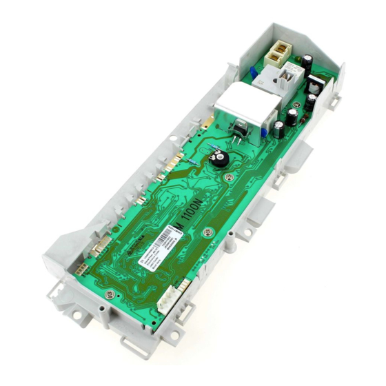
Page 59: Burning On The Circuit Board Ewm1100
10 BURNING ON THE CIRCUIT BOARD EWM1100 In case of burning on the main circuit board, check that the problem is not caused by another electrical component (short-circuits, poor insulation, water leakage). Refer to the figures below in order to identify the component that might have caused the burning according to the position of the burned area.